Week 3 Challenge : CFD meshing on Turbocharger
AIM:- CFD Meshing on Turbocharger.
OBJECTIVE:-
- Check for geometrical errors.
- Create PIDs.
- Assign PIDs.
- Perform surface mesh in the required target length.
- Blade stage-1 = 1 mm
- Blade stage-2 = 1 mm
- Impeller = 2 mm
- Shaft rotor = 1 mm
- Turbo casing = 5 mm
- Compressor casing = 5 mm
- Inlet casing cover = 5 mm
- Perform Volumetric Mesh.
PROCEDURE:-
- We run ANSA v22.1.2 software insatlled in our system.
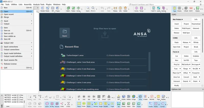
- We load the model of Turbocharger by selecting File>Open>Turbocharger1.ansa.
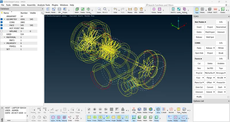
- The required model will load on the screen.
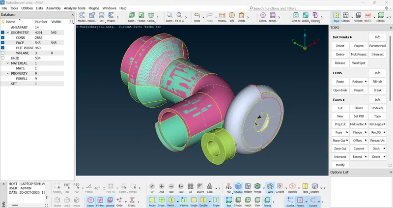
- Next, we select PID draw mode and activate shadow mode to get proper view of turbocharger model.
- Next we need to perform topological cleanup.
- We select the topo option from the faces menu section under topo deck to perform topo as a result of which we will find several triple cons in the model.
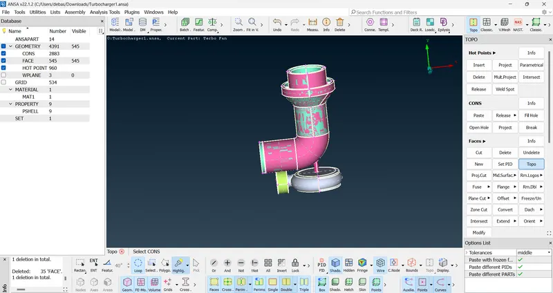

- Triple cons is being found due to the presence of overlapping surfaces in the model and the overlapping surface appears to be glitchy.
- To remove the triple cons we need to delete the overlapping surfaces. We perform it by selecting the delete option in the main menu and then appropriate selection of entity/PID and then delete it by clicking the middle mouse button and then clicking ok.
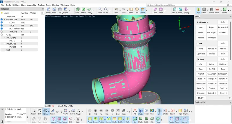
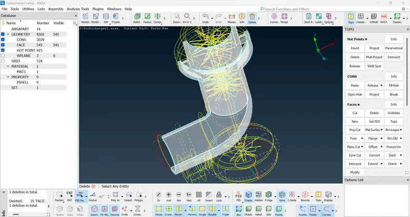
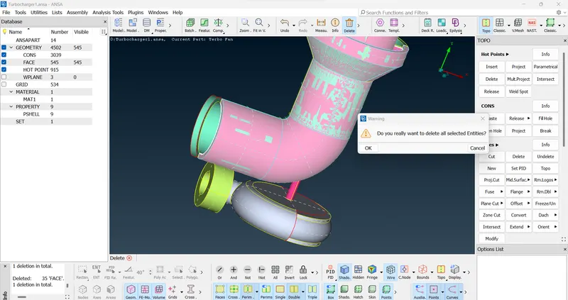
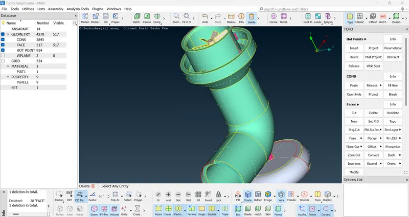
- After deletion of the overlapping surface we need to delete some extra surfaces present in the model by selecting the delete option and appropriate entity/PID.
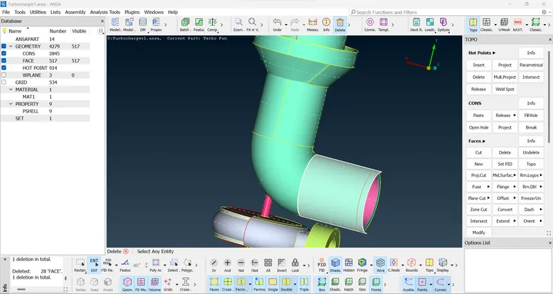
- After deletion of the extra surfaces we need to create new surfaces where single cons are forming to get a proper surface meshing.
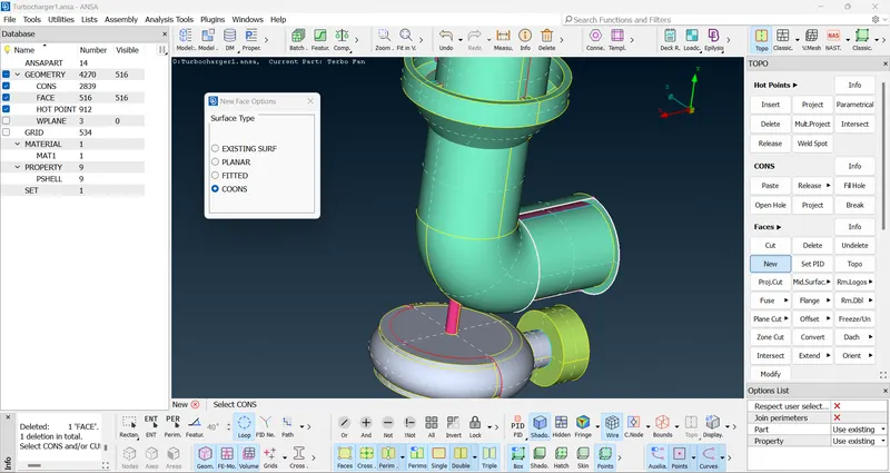
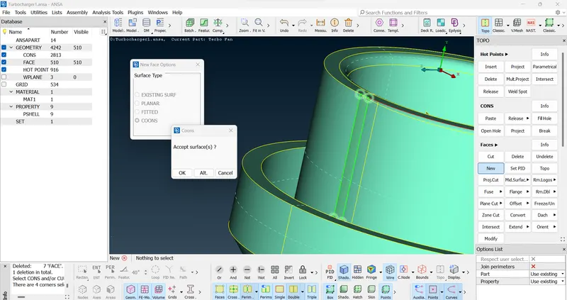
- We perform it by selecting the new option from the faces section under topo deck and then selecting the surface type and then selecting the appropriate cons/entity/PID and then clicking the middle mouse button to complete it by checking the preview as shown below and then clicking ok.
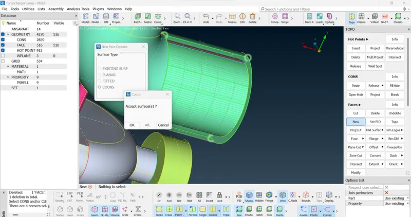
- We properly check the model and remove some more extra surfaces.
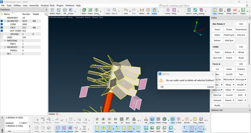
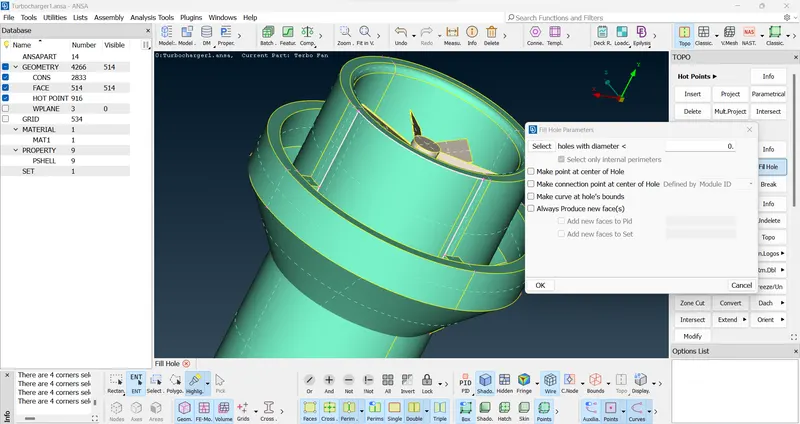
- Next, to create a particular surface, we need to project some nodes by selecting the cons where we want the nodes to be projected and then creating surfaces in sections to achieve a proper surface. We also use the fill hole option to fill existing surfaces as shown below in the following images.
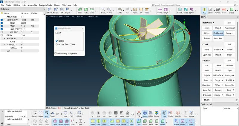
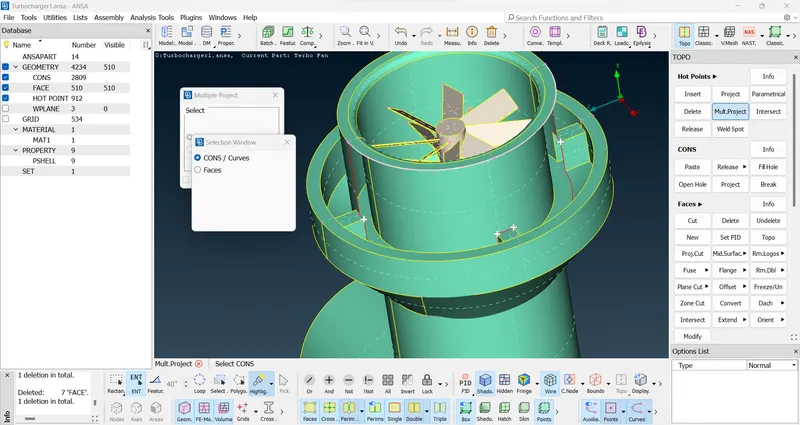
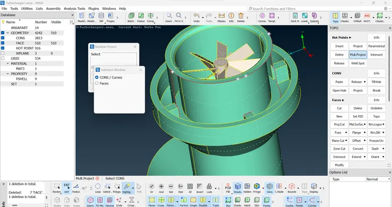
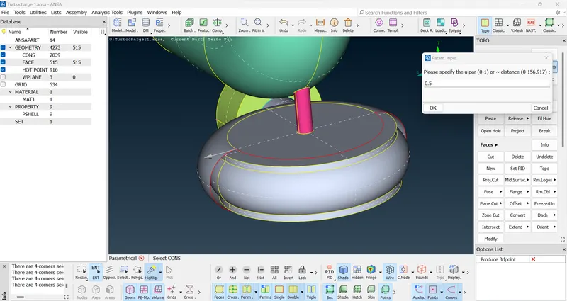
- Next, to create acurve surface we select the parametrical option under Hot points section under Topo deck to create nodes by giving proper directions and then creating nodes on the cons by assigning 0.5 as parametrical length.
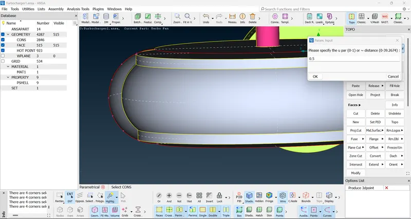
- After that we create curve surface in sections to achieve a proper curve surface by checking the preview before completing it.
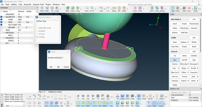
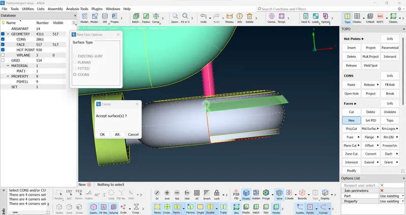
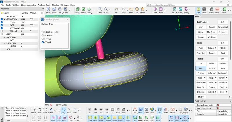
- Next, we inspect the model and find out a portion where the surfaces are not properly connected as a result of which single cons in being formed.
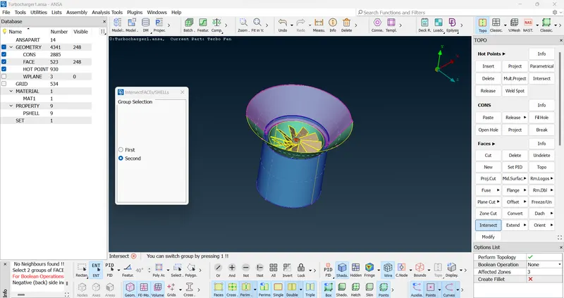
- To remove the single con from that part we need to select Intersect option from faces section, a menu will appear where we select the first and second surface and intersect it by clicking the middle mouse button to finally complete it.
- After intersection, an extra surface will be formed, we need to delete it by selecting the delete option and then we select the entity and remove it.
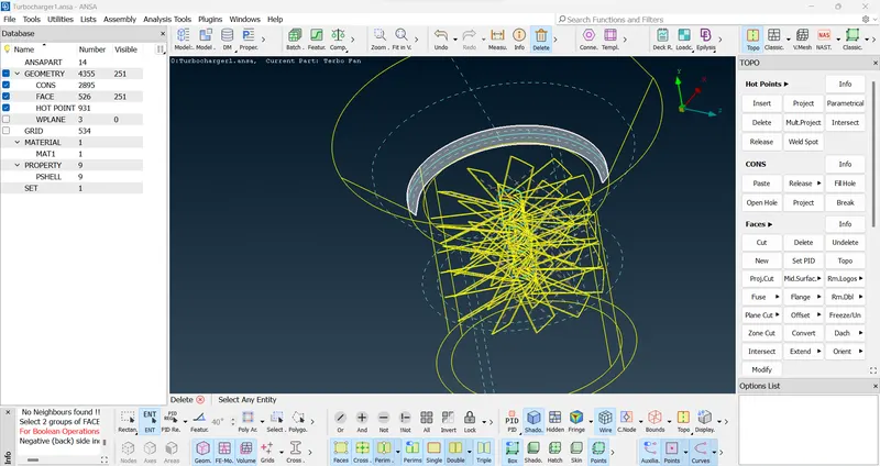
- Next, we check for more overlapping/extra surfaces present in the model by clicking control+shift button together to see it in a wireframe mode and then deleting it.
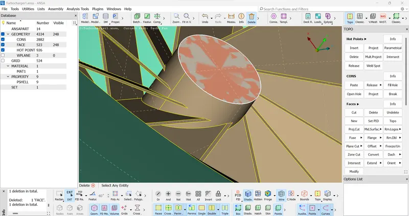
- We also use the release option under cons section to fix some of the triple/single cons to make it a double con by performing topo function after releasing the cons.
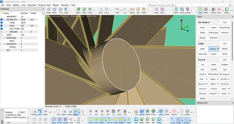
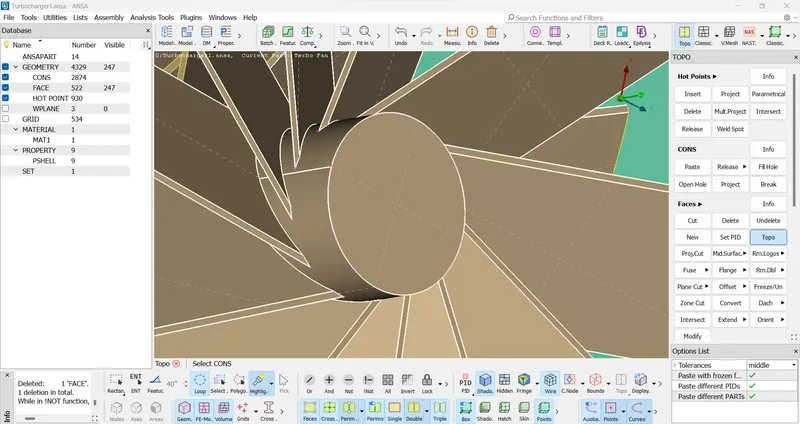
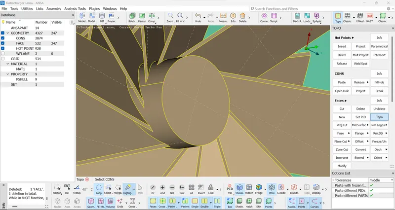
- Then on regular interval we perform the geometry checks for finding the errors related to single and triple cons.
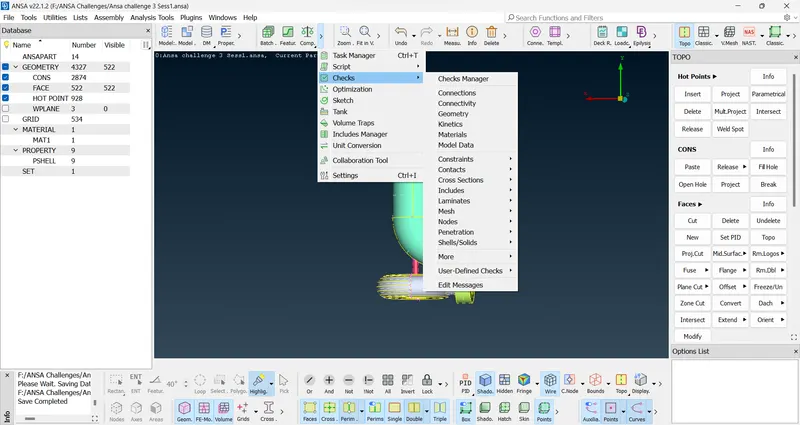
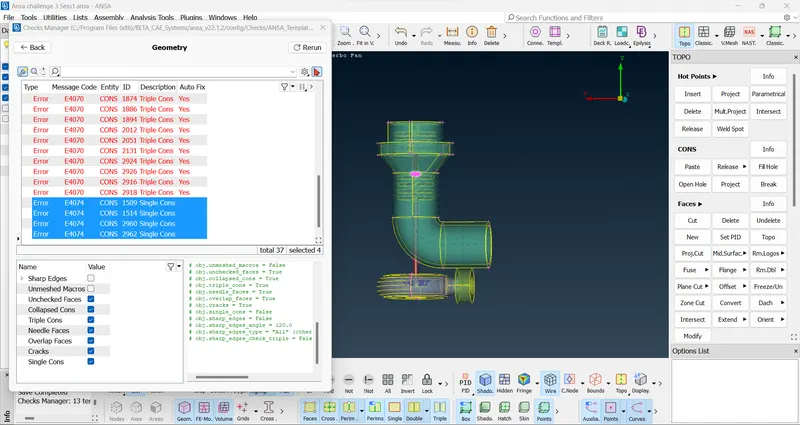
- Geometry checks results a few errors which we need to fix.
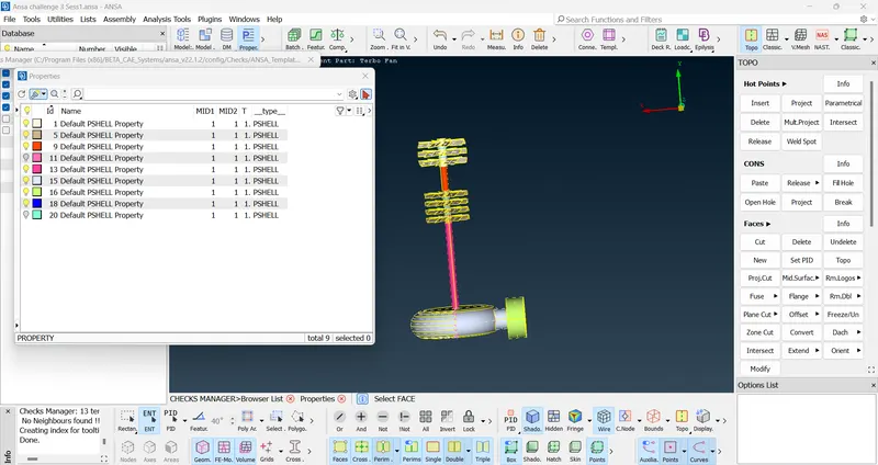
- With the help of PID manager we hide the unwanted PIDs to perform the necessary fixation.
- We fic the single cons error by running the topo function and fix the triple cons by deleting overlapping and extra unnecessary surfaces to achieve a proper surface meshing.
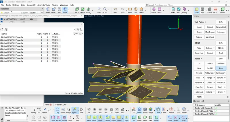
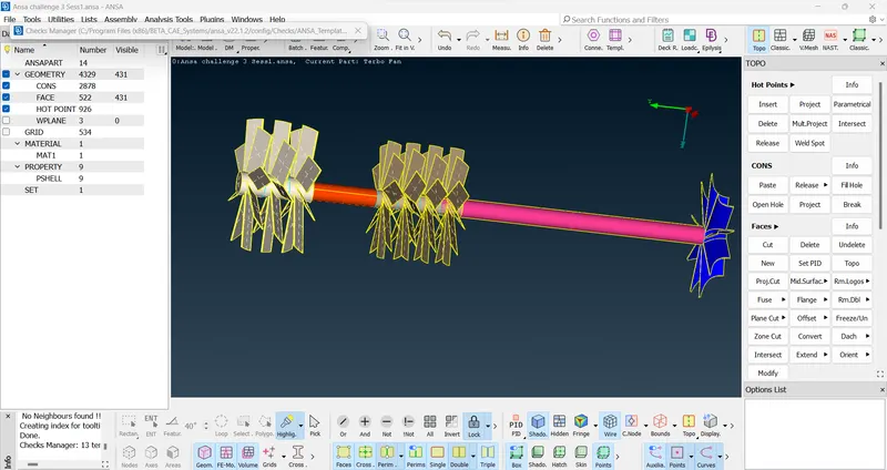
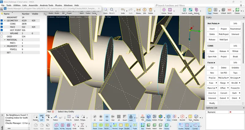
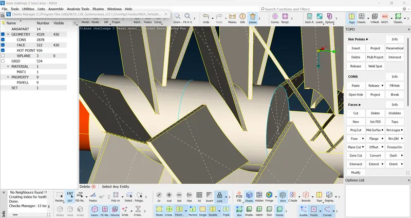
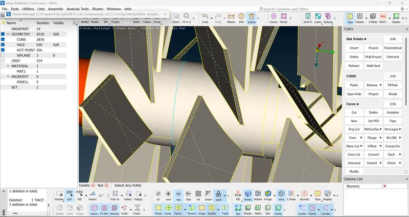
- While removing triple cons we find a part where there was no double cons in a portion in the shaft. To create it we project the overlapping surface cons onto the shaft by selecting the project option under cons section.After that few more unwanted triple cons were removed.
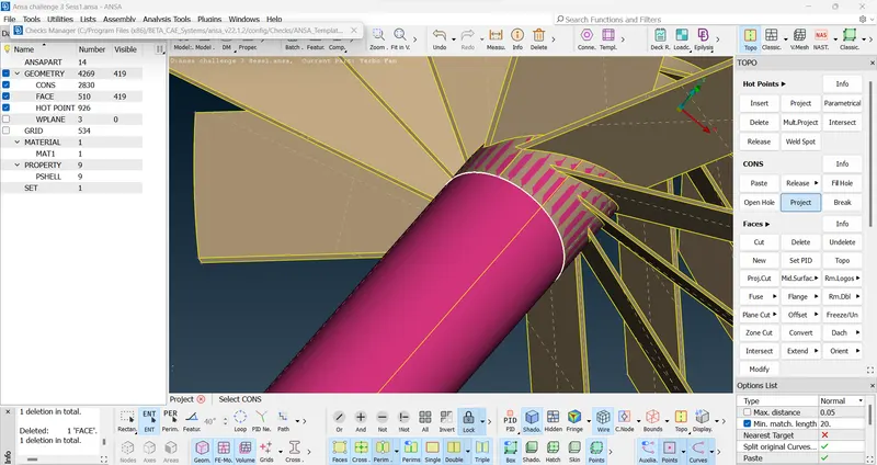
- To delete some surface we need to use the cut option under faces section and make cuts on the surface with the help of nodes and then deleting the extra surface.
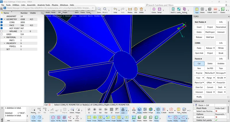
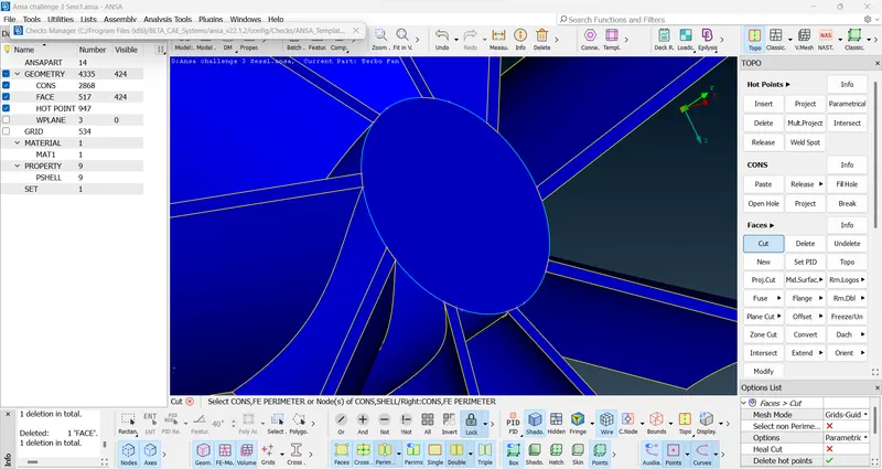
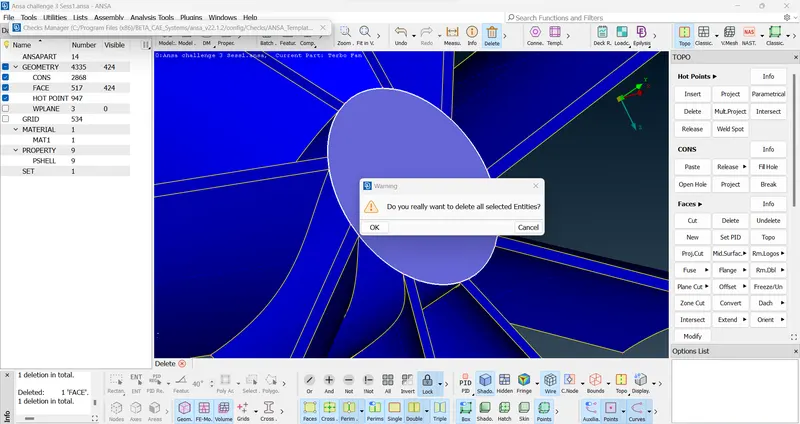
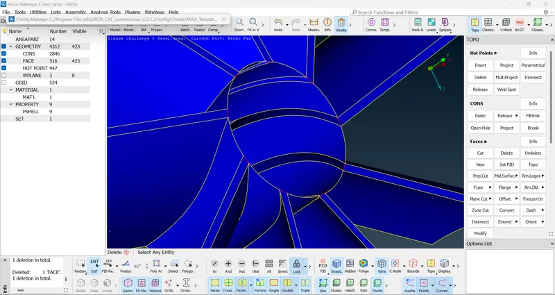
- We again perform the geometry check to look for errors. Few error related to triple con was found which was necessary for the model.
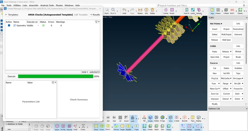
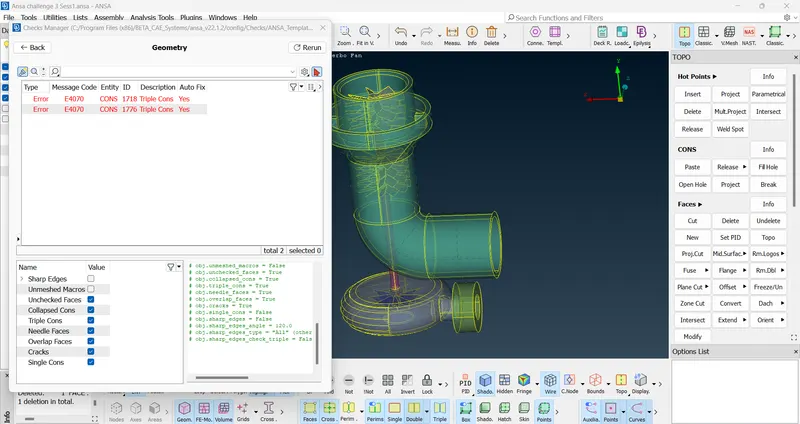
- Next, with the help of PID manager we select different PIDs and create new surfaces to close the model for proper meshing.
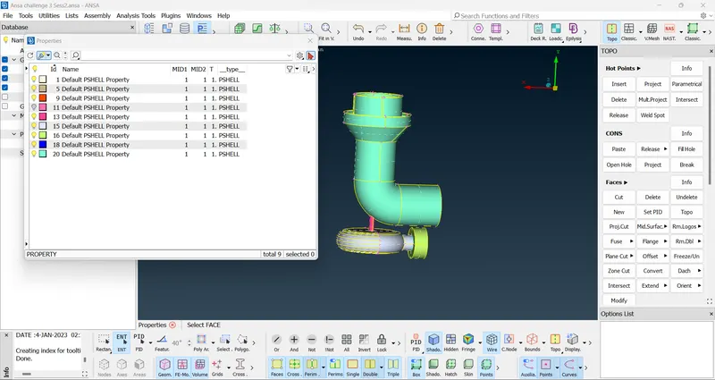
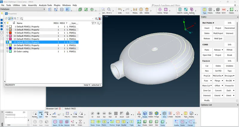
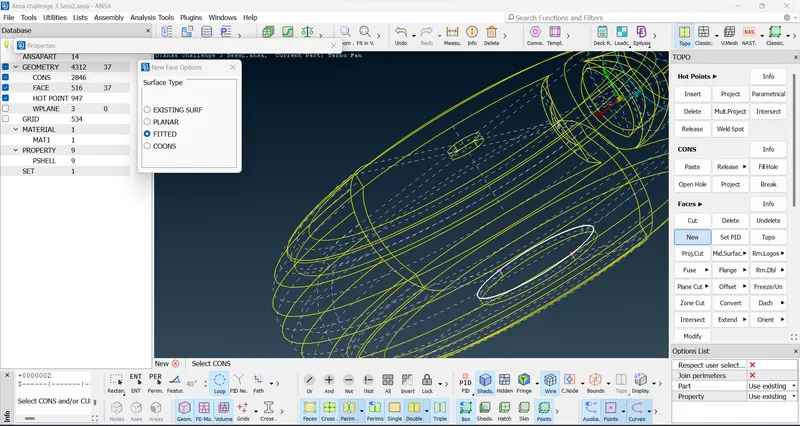
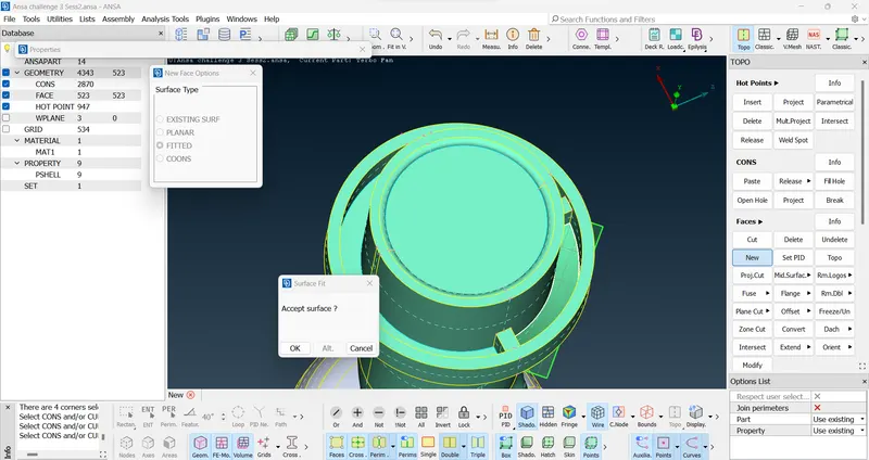
- Next we create few more PIDs and assign them appropriately.
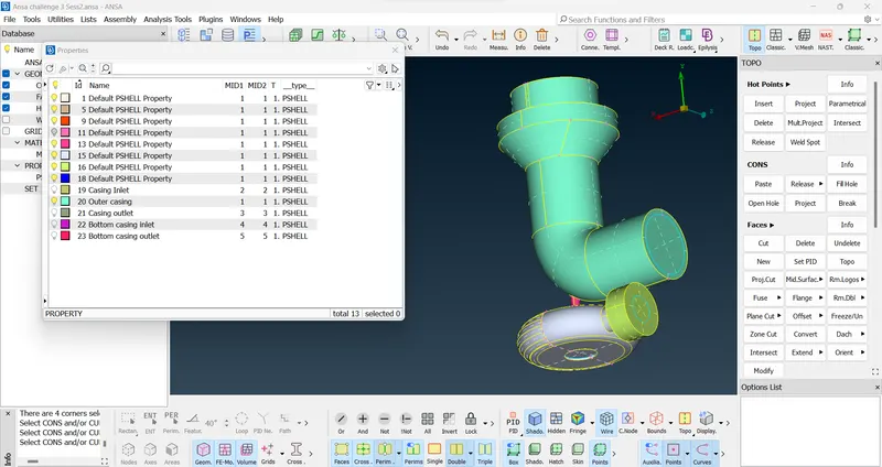
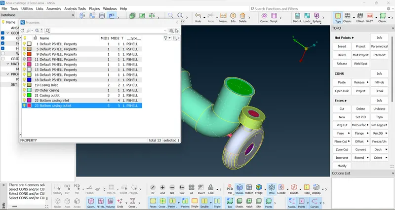
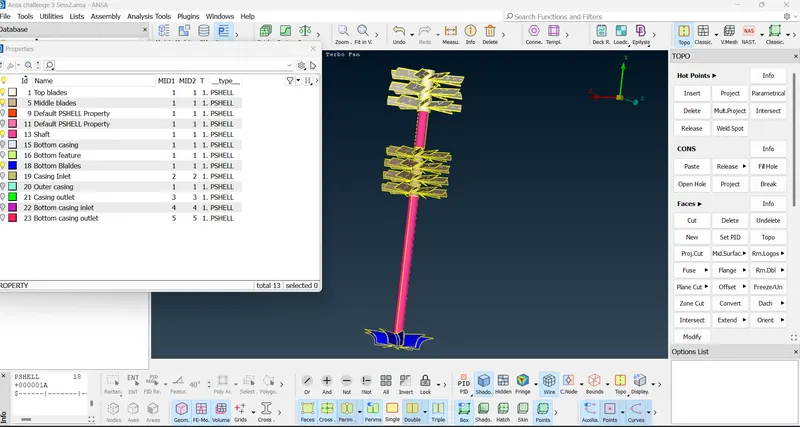
- Next we delete the unwanted PIDs by selecting the compress option and then deleting it.
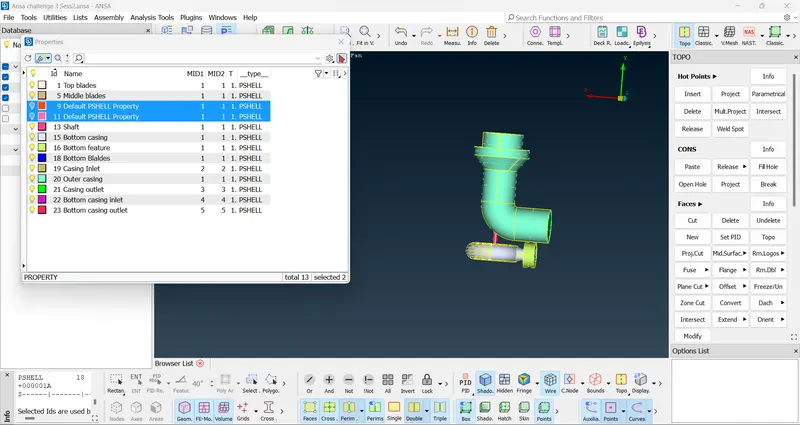
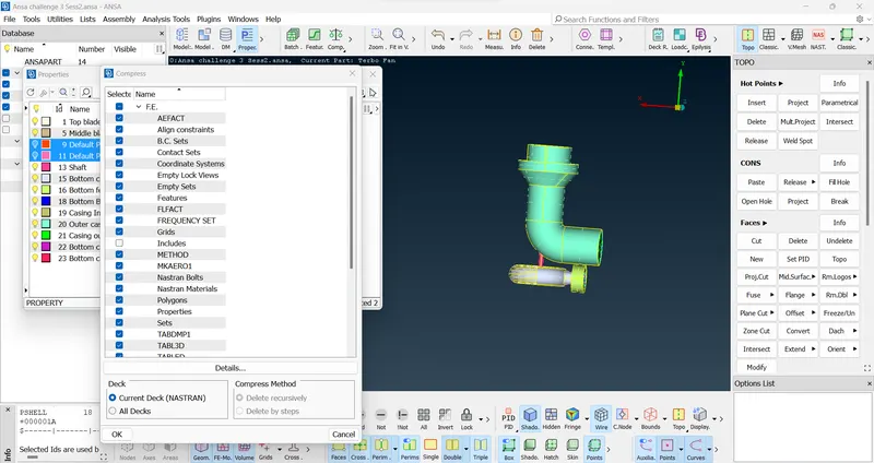
- Next, we rename the assigned PIDs to its appropriate names.
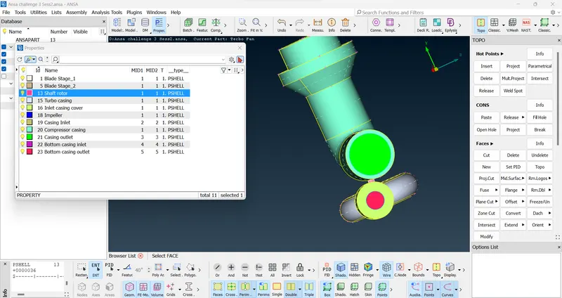
- We again delete few more extra surface and overlapping surfaces to nullify single cons. Errors were found related to triple cons but it was necessary, so we don't remove it.
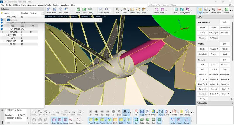
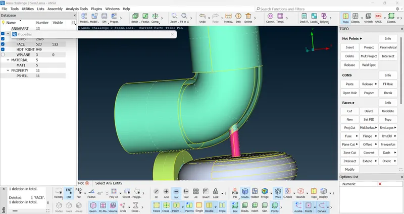
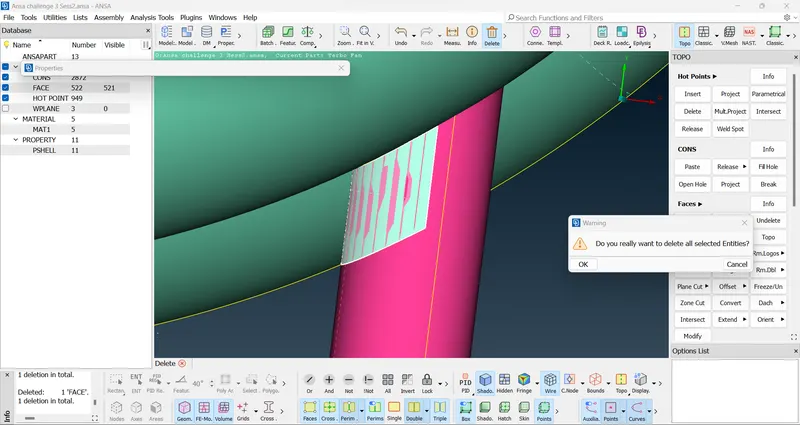
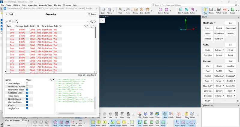
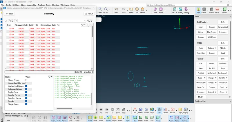
- Topological cleanup is completed.
- Next, we perform surface meshing by selecting different PIDs as required.
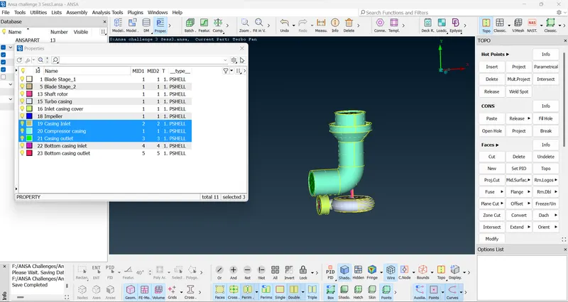
- First, we selct the casing inlet, compressor casing and casing outlet and select show only option by clicking the right mouse button and then sclicking on show only.
- Next, we set appropriate quality parameters by giving minimum and maximum length as we a target length of 5 mm is required.
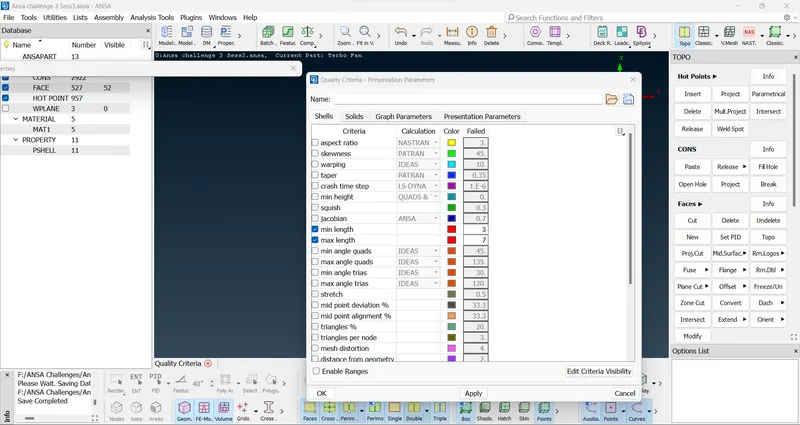
- Next, we select the mesh parameter option and select element type as tria and assigning the target length as 5 mm.
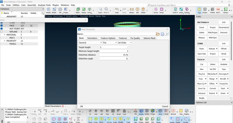
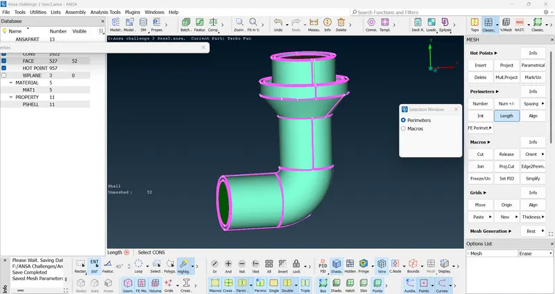
- Next, we select length option from perimeters section under mesh deck and then assign perimeters and macros of target length 5 mm by making a box selection on the appropriate PIDs.
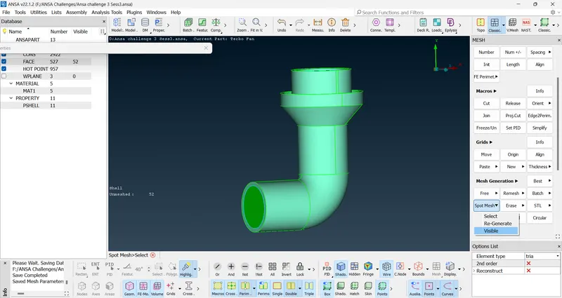
- Next, we create the surface meshing by selecting spot mesh and then visible option under mesh generation section to create surface meshing on the selected PIDs.
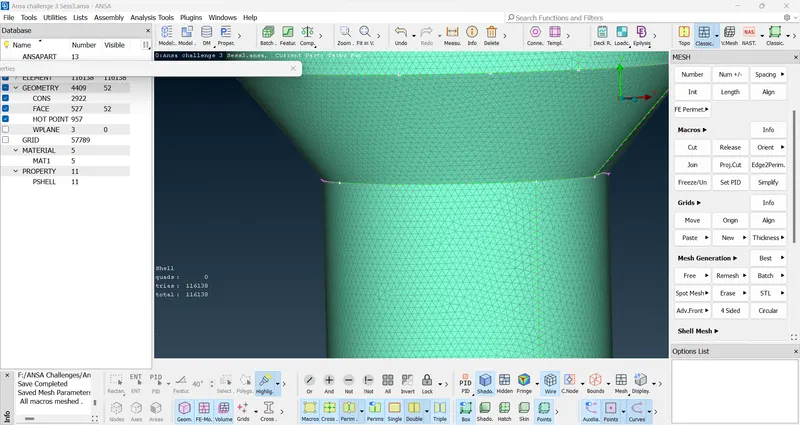
- Next, we select Turbo casing and Inlet casing cover PIDs and perform surface meshing on it by repeating the above steps and by selecting appropriate target length as required.
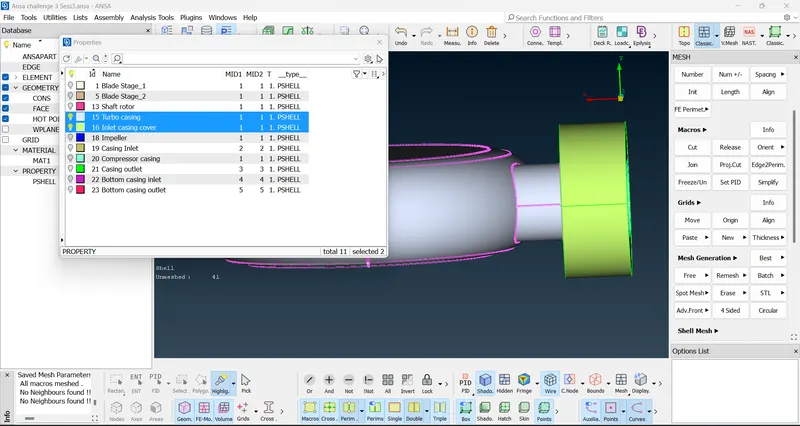
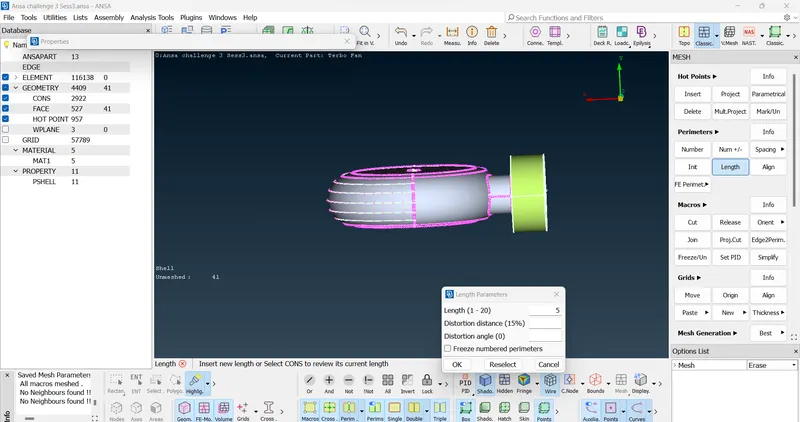
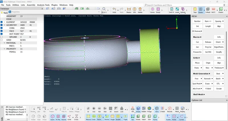
- Next, we perform meshing on other PIDs by performing the same steps and changing the target length as required.
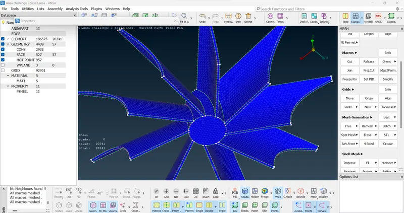
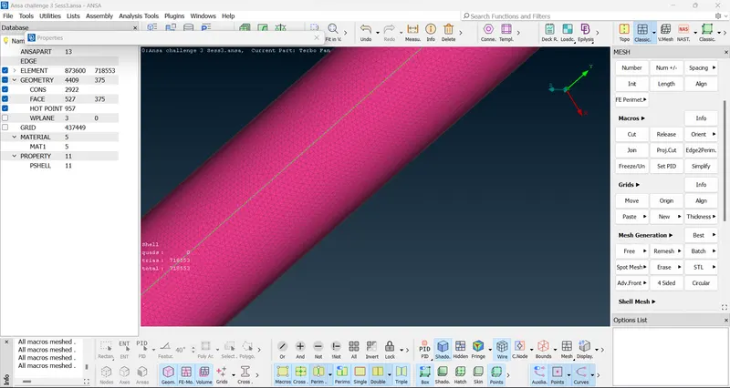
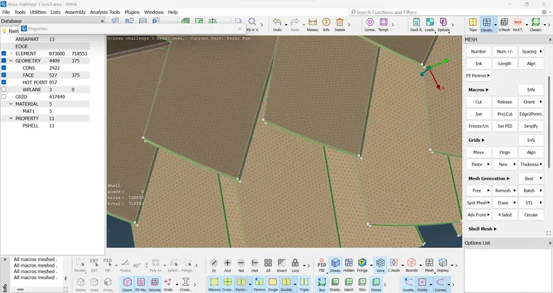
- Some surfaces were having meshging errors due to difference in traget length. To fix that we performed surface meshing again by selecting the appropriate entity and PID and assigning required target length. There was more difference in target length near the points where the target lengths changed suddenly.
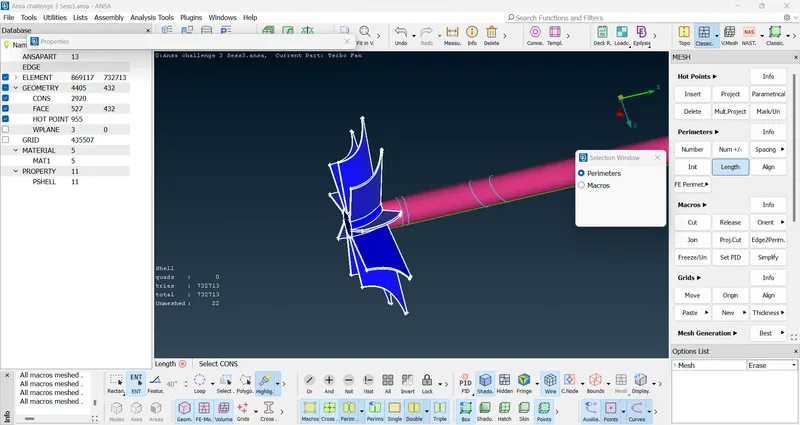
- To achieve a proper meshing we created additional cuts in the surface near the change in target lengths to reconstruct the meshing quality.
- We selected cut option from macros section under mesh deck and selcting reconstruct and parametrical options from the options list and did cuts on the surface.
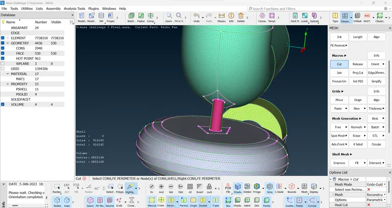
- We completed the surface meshing in the required target length of 5 mm, 3 mm and 1 mm respectively. Meshing is done properly as there was no unmeshed surface shown.
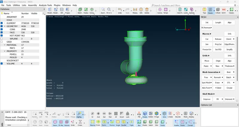
- Next, we perform volumetric meshing. First we selct define option under volume section under volume mesh deck.
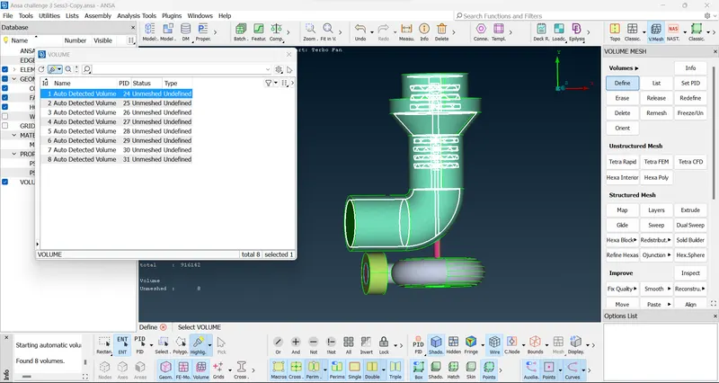
- Nect, we delete the unwanted volumes by selecting them from list option and by clicking the right mouse button and then deleting it wisely as required.
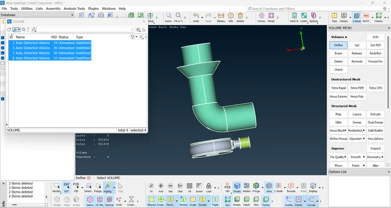
- After deleting unwanted volumes we select all the remaining volumes and then select the show only option by clicking right mouse button.
- Next, we assign volumetric meshing by selecting Tetra CFD option under Unstructured Mesh and then selecting the appropriate PIDs and assigning it. As a reult volumetric meshing is completed by repeating the same steps for other PIDs.
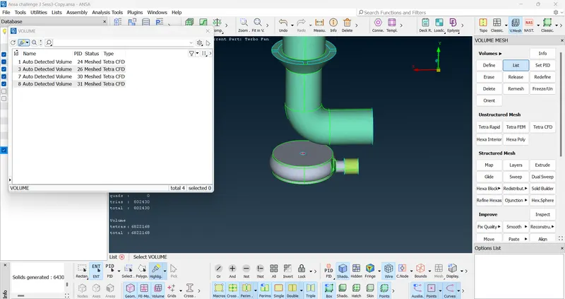
- Next, we check the volumetric meshing under top deck by selecting the volume option only.
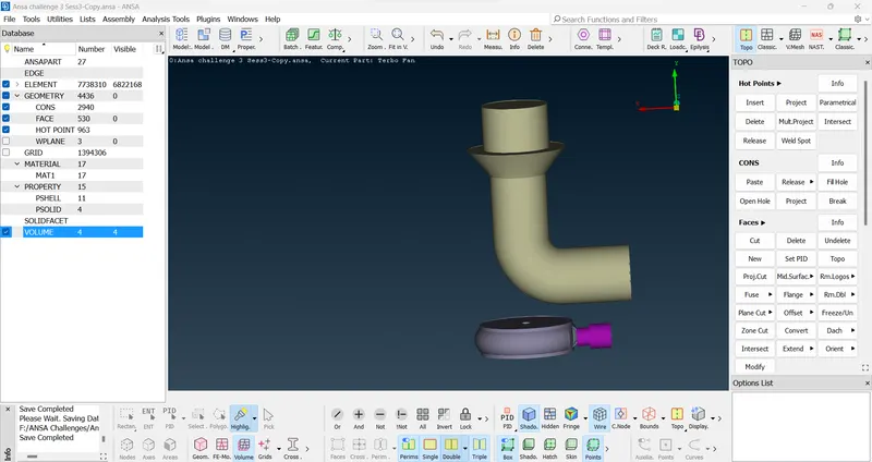
- As seen above, volumetric meshing is done properly.
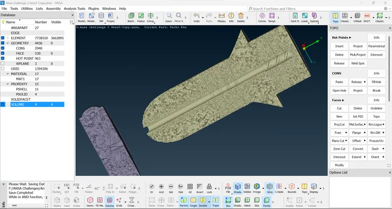
- Next, we do a section cut in between the model to see the volumetric meshing in required target lengths.
LEARNING OUTCOMES:-
- We learnt to perform topology cleanup such as deleting overalapping surfaces, unwanted extra surfaces, removing sinle cons and triple cons, as well as creating new surfaces as required in the turbocharger.
- We learnt to intersect new surfaces, project cons to an another surface by the help of overlapping surfaces, create cuts to form a surface and then deleting it.
- We learnt to create new PIDs and assigning them and renaming them.
- We learnt to create surface meshing by assigning different target lengths and element type to different PIDs together by proper selection of PID/entity.
- We learnt to create Volumetric meshing by selecting appropriate needed volumes in the element type of Tetra CFD.
- We learnt to view the volumetric meshing in cutting a section.
RESULT:-
- We find no geometrical errors as there was no single cons.
- PIDs were created and assigned properly.
- Surface meshing done properly in the required objective as there was no unmeshed PIDs.
- Volumetric Meshing done properly in the element type Tetra CFD.
CONCLUSION:-
OUTPUT FILE:
https://drive.google.com/file/d/19VTCXXmQCmliI0PrA7v84UeJVwmbWJSC/view?usp=share_link