Week 3 - External flow simulation over an Ahmed body.
Aim:-
Simulate the flow over the Ahmed body and use air as the working fluid with velocity of 25 m/s.
For this challenge, you will have to provide answers to the following questions:
- Describe Ahmed’s body and its importance.
- Explain the reason for the negative pressure in the wake region.
- Explain the significance of the point of separation.
Expected results:
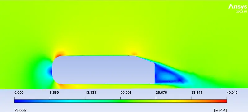
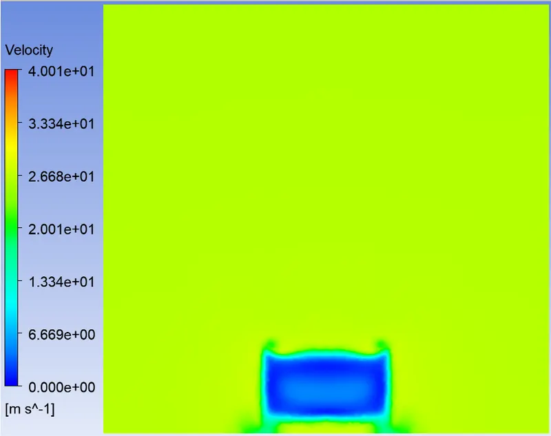
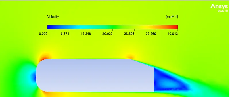
- Velocity and pressure contour.
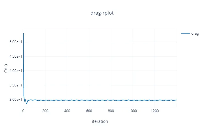
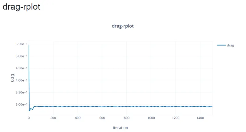
- The drag coefficient plot for a refined case.
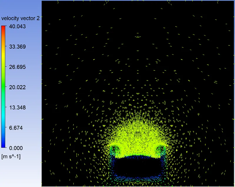
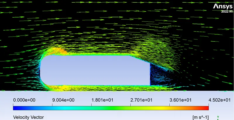
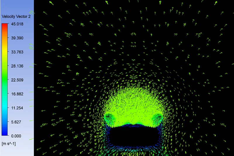
- The vector plot clearly showing the wake region.
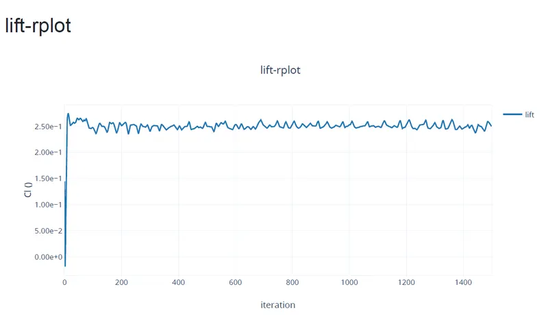
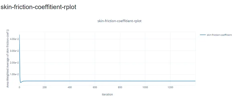
- Perform the grid independency test and provide the values of drag and lift with ease case.
Note:
- Setting the reference values in Fluent is necessary to get the correct drag value.
- As the body is perfectly symmetric, we can run the simulation by considering the half body alone. This is the best practice where you can save on the number of cells and get the results faster as well.
Introduction:-
- Ahmed body :-
The Ahmed body is a generic car body (a simplified vehicle model). The airflow around the Ahmed body captures the essential flow features around an automobile and was first defined and characterized in the experimental work of Ahmed [1]. Although it has a very simple shape, Ahmed body allows us to capture characteristic features that are relevant to bodies in the automobile industry.
The pic below shows the dimensions od Ahmed body. but there is a other thing the angle of rear part is not defined means it can vary, if the angle is varied we are able to get new results on different angles. based on which we can descide that which one will produce more drag. This model is also used to describe the turbulent flow field around a car-like geometry. Once the numerical model in validated, it is used to design new models of the car. 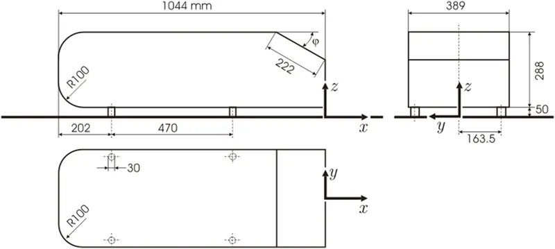
- Importance of Ahmed Body :- The flow of air around Ahemd body captures the essential flow features around an automobile and it describes how to calculate the turbulent flow field around a simple car-loke geometry using the turbulent, flow, K-epsilon interface. People working in vehicle aerodyanamics use Ahemdbody to validate their numerical model because the experimental data for Ahemd body. Once the numerical model is validated, its is used to design new models of the car and also used for faster calculation and for comparision of analytical results.
- Significance of the point of separation :- The separation point is the point where the air stops "sticking" to an object that is moving through the air. When an object is moving through the air, the air molecules push back on it and resist the object's movement - this resistance is called pressure drag. As the air flows around the object, it "sticks" to the object, forming what is known as the boundary layer. This "attached flow" is flowinf very smoothly. The point on the body where the boundary layer lifts off the surface is called the separation point. When the air flow separates off the surface, the pressure drag usually increases.
Procedure:-
- First We will import the model in the Fluent model .
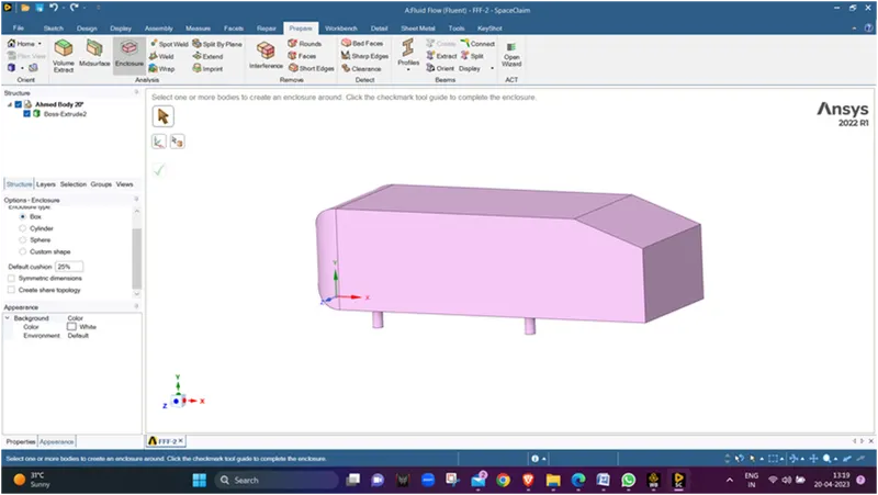
- Now we will measure the length of the model.
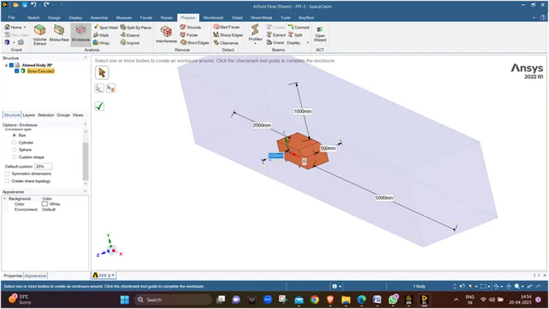
- Now We will make an enclosure around the ahmed body considering front distance from front face as 2x, rear distance from rear face as 5x side distance from side faces as 0.5x ,top disance from top face as 1x and for bottom its 0.
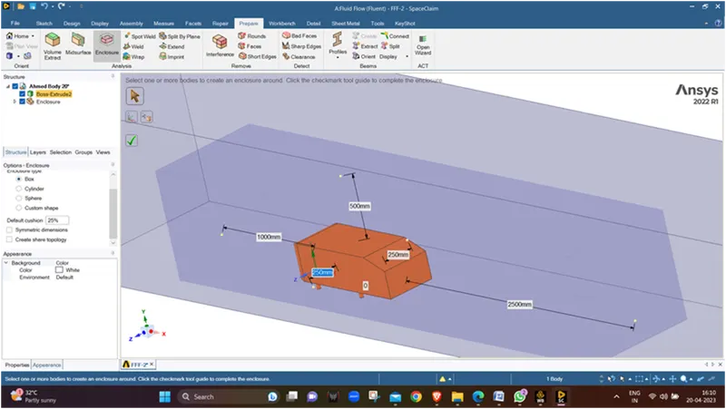
- Now we will create an enclosure of almost half the dimension over the ahmed body, we are creating the enclosre make a refined mesh inside the enclosure.
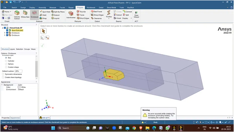
- Now we will supress the body for physics .
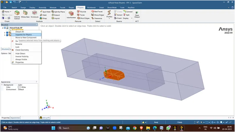
- Now we will split the whole enclosure with a plane using a Split Body Command.
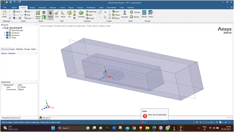
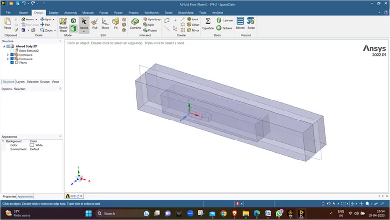
- Now we will delete the front split part.
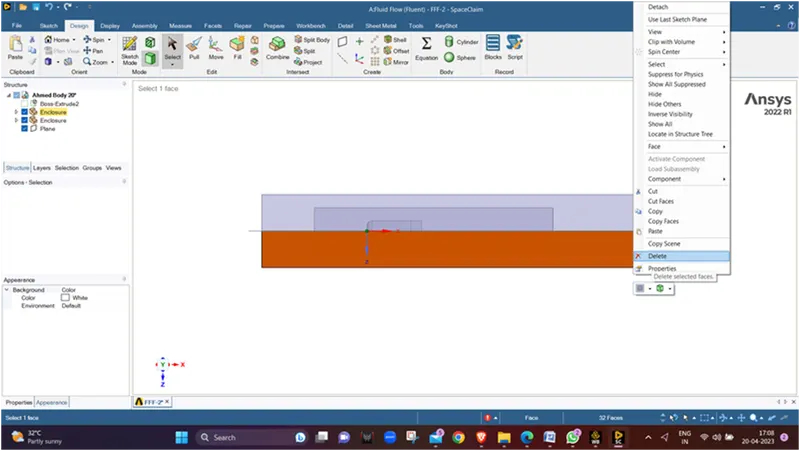
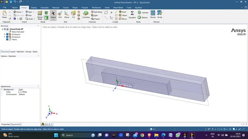
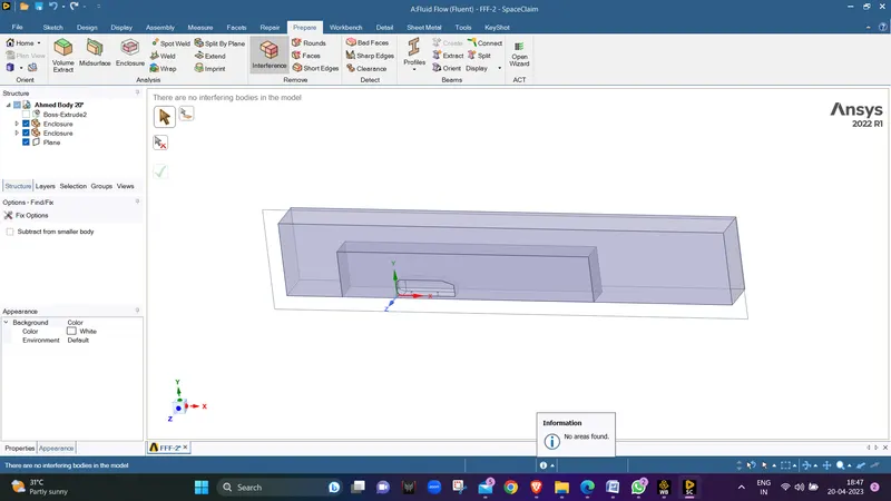
- As we know we hace made enclosue over an enclosure so there will be interference in the whole model so we will use interference command to finfd out where the interferanc is and remove it.
-
We can see that now there is no interference left in the body so now we will do share topology for the 2 enclosures so that at the ends of the enclosure the meah can be properly captured and evenly devided.
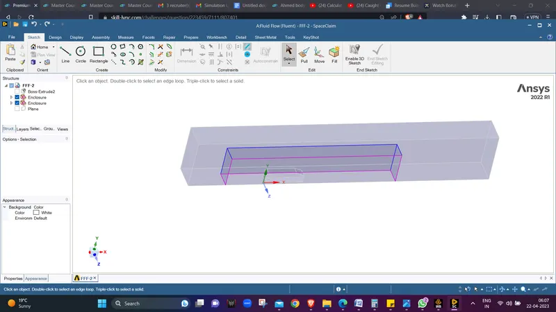
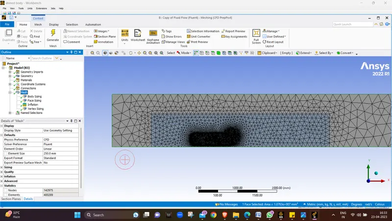
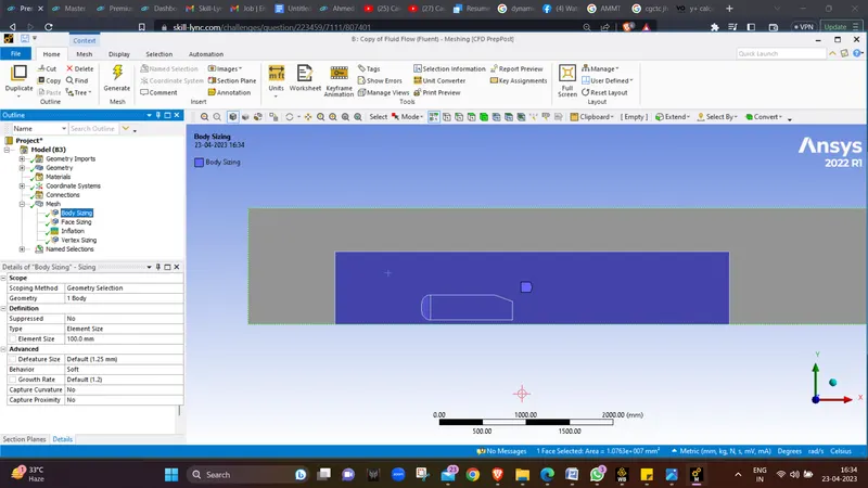
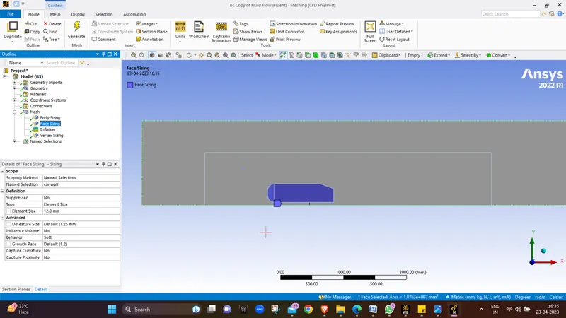
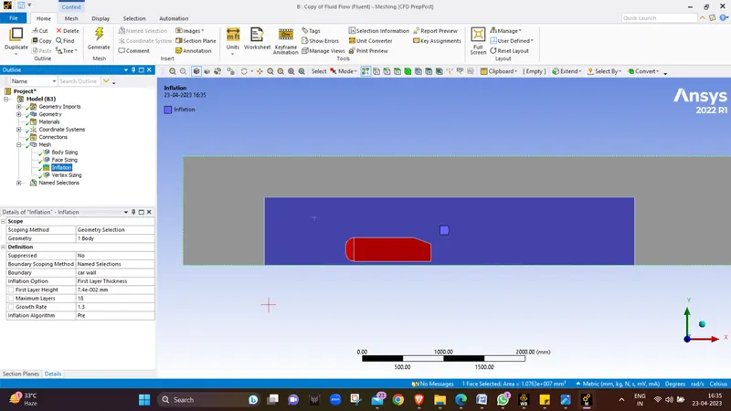
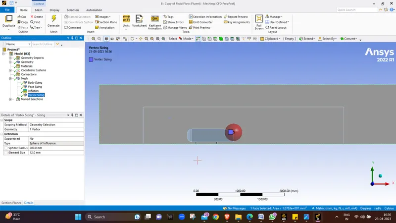
- Now we will open mesh module and mesh the model with a desirable mesh for outer enclosure we will use 250 mm as element size and for inner enclosure we will keep the size as 100 mm and for the car wall face sizing with 10 mm as the element size and we will give inflation layers at the car wall with First cell thickness as 0.074 mm and number of layers to be 18 with growth rate of 1.3 and y plus value as 5.
- We will also add vertex sizing and select sphere of Influence and give the radius as 200 mm and 12 mm for the element size , we are adding this Sphere of influence in the back side of the hmed ody to get a proper result that how flow properties varry at the point when flow leaves the body.
- Now we will move to the solver settings.
SOLVER SETTINGS :-
- We will open the setup window to proceed with the initial conditions for simuating the Ahmed Body .
- We will use k-ω SST model for this simulation.
- Materials as air (default).
- In cell zone condition check for fluid.
- At the boundary condition define Inlet with a velocity of 25 m/s.
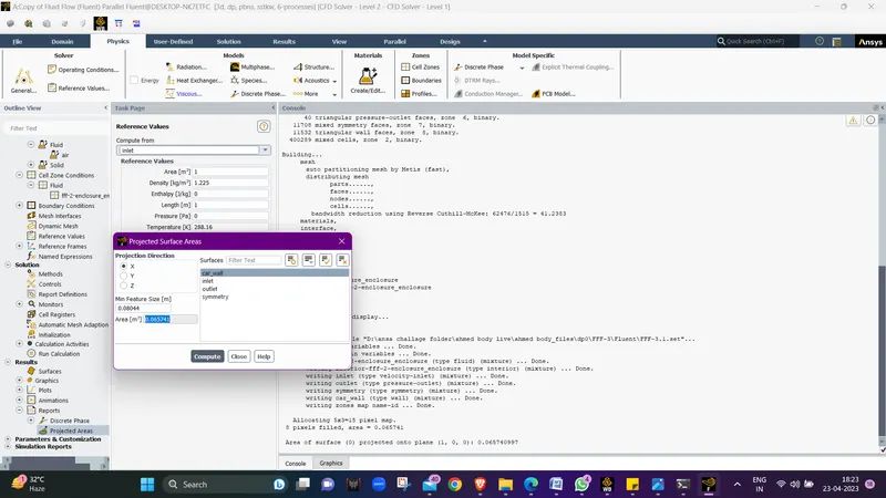
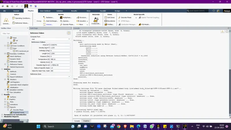
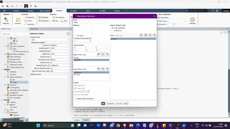
- Now we will go for reference values from inlet and the area we will get from the reports the area should be perpendicular to car wall in x direction then we will copy it and paste it in the area tab of reference values, area is 0.065741 m2 and length is 1.044 m.
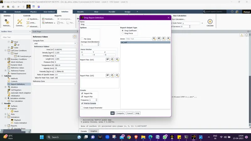
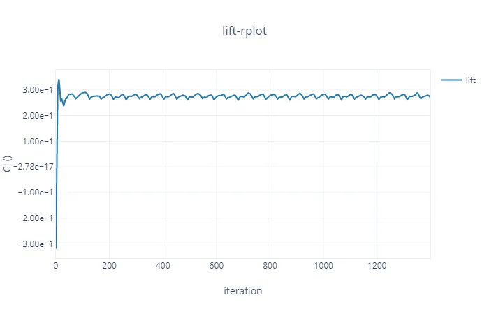
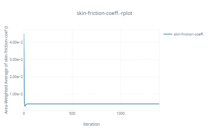
- Now we will assign report definations in the simulation for LIFT ,DRAG and Skin Friction coefficient plots.
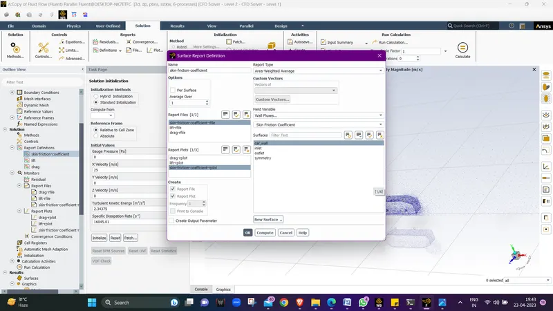
- Now we will do the initialization in Standard format and compute from Inlet.
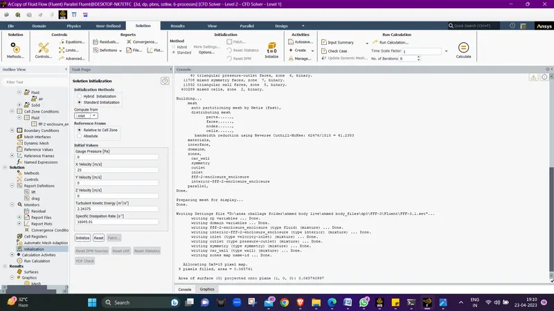
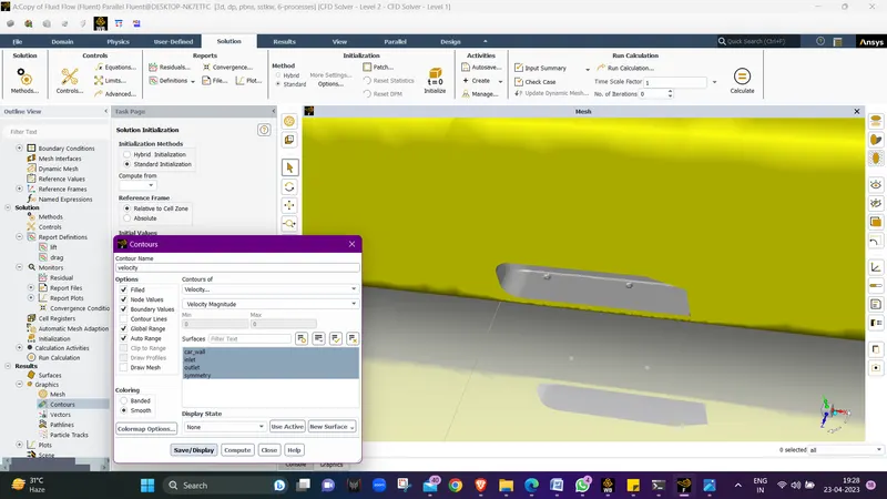
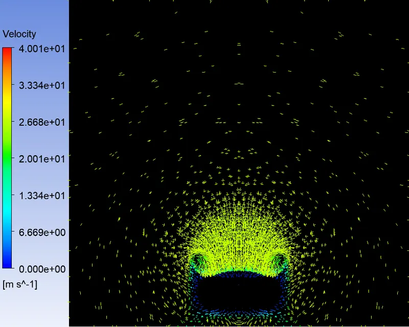
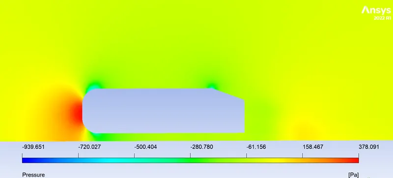
- Now after initialization we will set the contour plots for Velocity, Pressure and Velocity vector for all the boundary conditions.
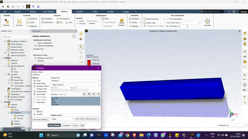
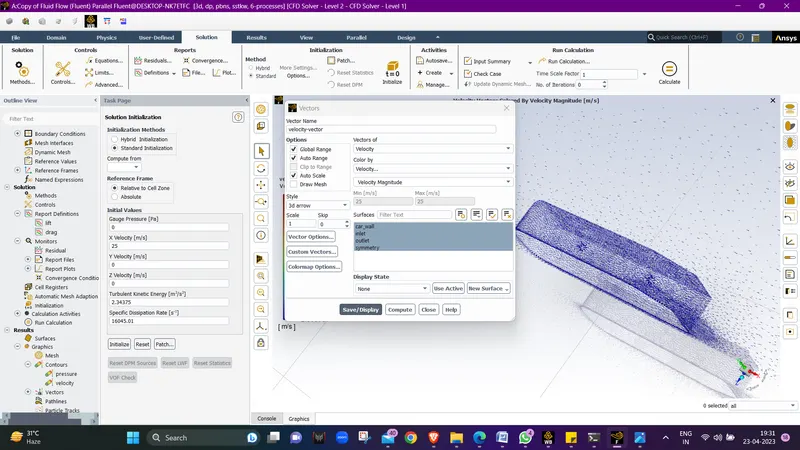
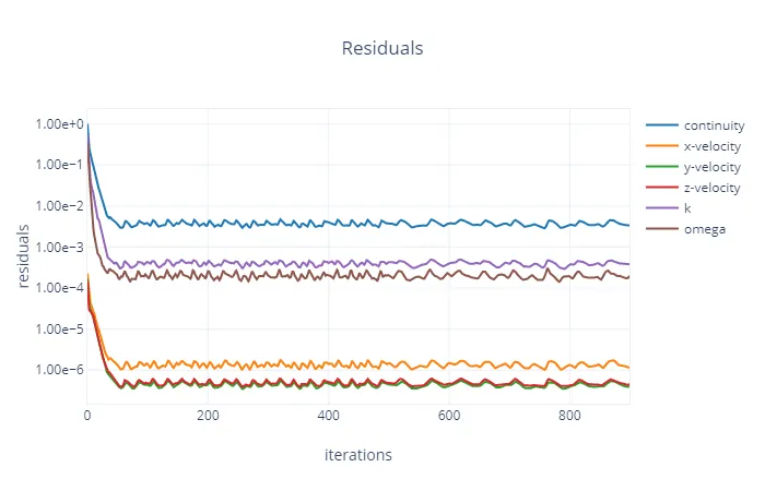
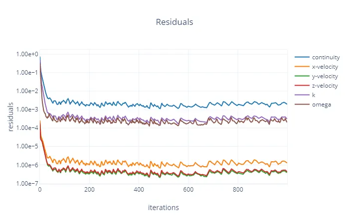
- Now we will calculte the results using 500-1000 iterations or more to capture the results in form of plots till the solutions get converged.
Plots :-
Case 1 :-
Residual plot :-
Drag plot :-
Lift Plot :-
Skin Friction Coefficient Plot :-
Velocity Contour Plot 1 :-
Velocity Contour Plot 2 :-
Velcity Vector Plot 1 :-
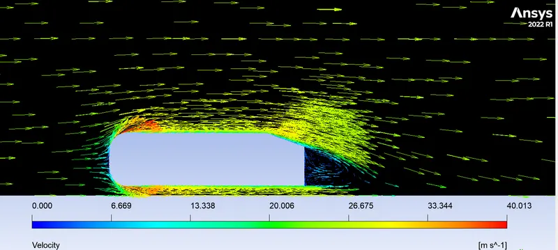
Velcity Vector Plot 2 :-
Pressure Contour Plot :-
Case 2 :-
Residual plot :-
Drag Plot :-
Lift Plot :-
Skin Friction Coefficient Plot:-
velocity Contour Plot 1 :-
velocity Contour Plot 2 :-
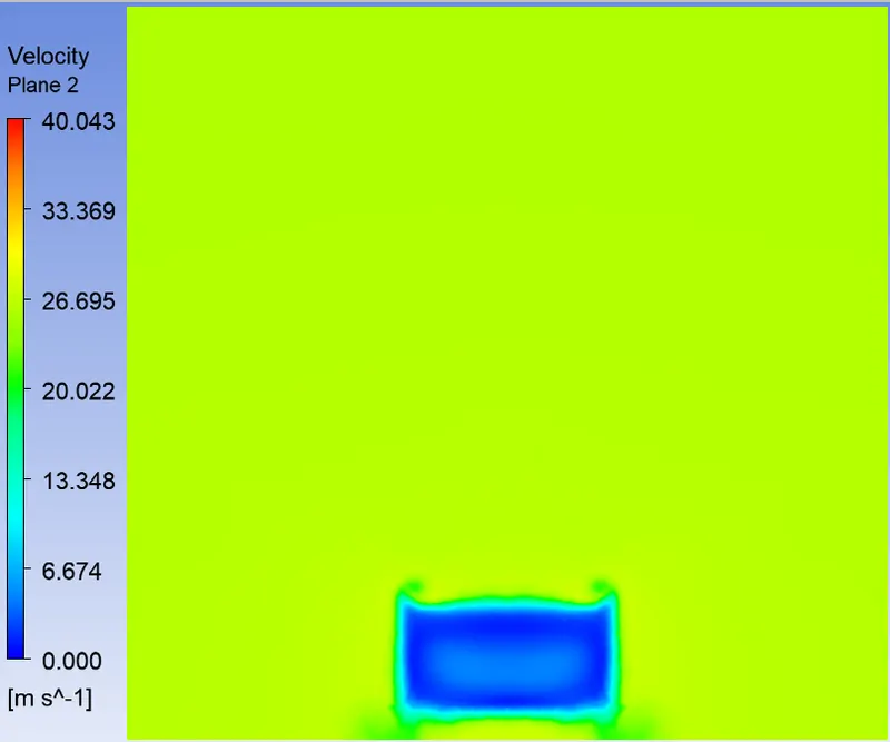
Velcity Vector Plot 1 :-
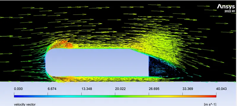
Velocity Vector Plot 2 :-
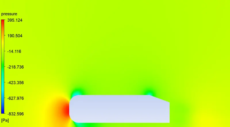
Pressure Contour Plot :-
Case 3 :-
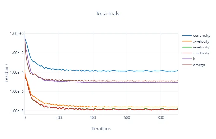
Residuals :-
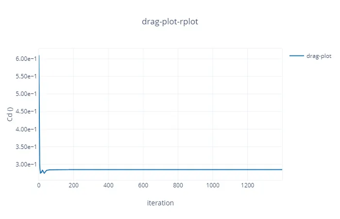
Drag Plot :-
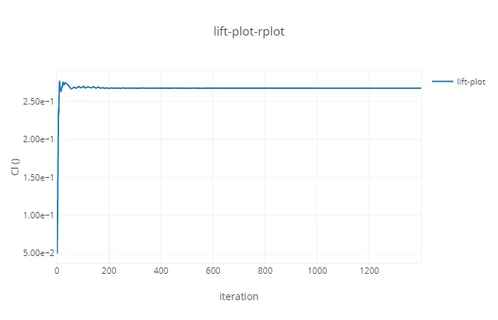
Lift Plot :-
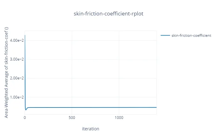
Skin Friction Coefficient Plot:-
Velocity Contour 1 :-
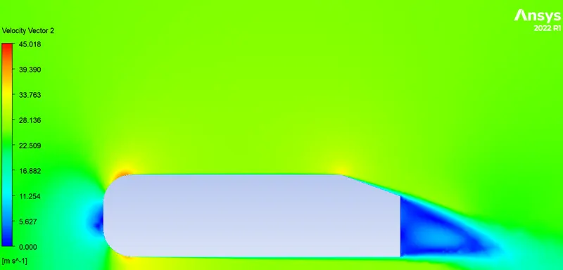
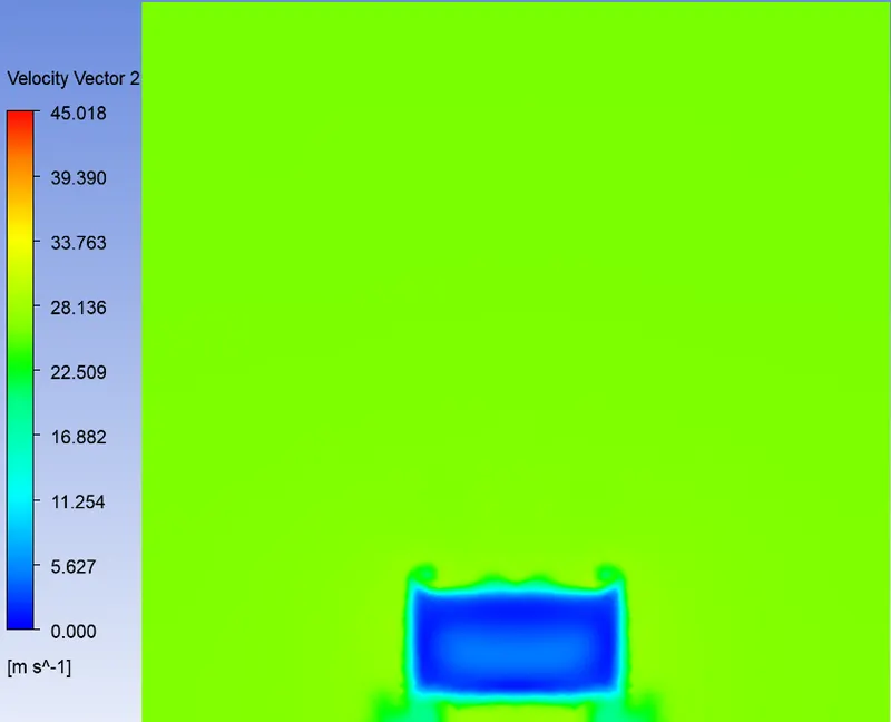
Velocity Contour 2 :-
Velocity Vector Plot 1 :-
Velocity Vector Plot 2 :-
Pressure Contour Plot :-
Grid Independency Test:-
| Cases | Nodes | Cell count | Drag | Lift | Skin Friction Coeff. |
| Case 1 | 142975 | 400289 | 0.2986471 | 0.2694248 | 0.004365587 |
| Case 2 | 200714 | 566519 | 0.2906391 | 0.2500371 | 0.00433399 |
| Case 3 | 310788 | 885742 | 0.2847156 | 0.2674063 | 0.004540476 |
- There are notable changes in the three cases, mesh is more refined from case 1 to 3 to check the grid dependecy.
- A smoother mesh provides a more accurate results, from all 3 cases we can conclude that the flow is more defined at lower elemets size
- The finer the mesh gets, the easier it gets in visualizing the contours.
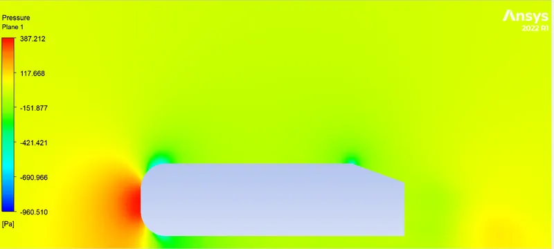
- Why the pressure goes negative
- Pressure goes negative to maintain the flow when there is an increase in the velocity of flow
- It can be the result of flow separation at the curved surface interferance of the body.
- Separtion bubbles are produces due to flow separation which results in negative pressure values.
- The pressure also becomes negative due to flow recirculation and to counter balance the effect of shear stress.