Week 3 Challenge : CFD meshing on Turbocharger
Aim :- To check for the geometrical errors to make appropriate volumes.
Create and assign PIDs as shown in the video. Perform surface mesh with the given target lengths as per PIDs.
- Blade stage-1 = 1 mm
- Blade stage-2 = 1 mm
- Impeller = 2 mm
- Shaft rotor = 1 mm
- Turbo casing = 5 mm
- Compressor casing = 5 mm
- Inlet casing cover = 5 mm
Perform Volumetric mesh for the required volumes.
Procedure:-
1. First open up the geometry downloded from the chaalnge window.
2. The window will open up with the geometry.
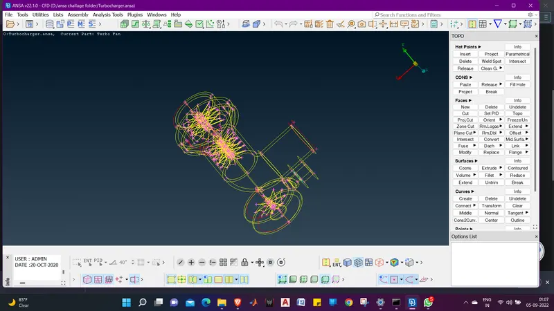
3. As we can see the model opened in wireframe mode showing red coons in the interface.
4. We will now switch to the shadow mode.
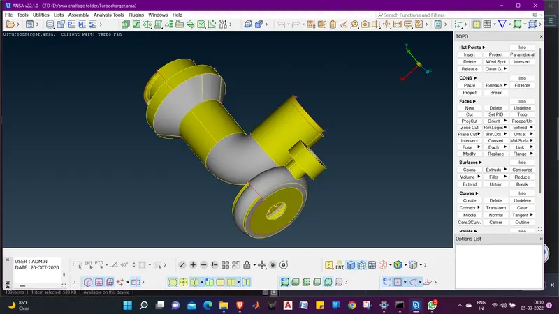
5. When we inspect the model we see many surface missing.
6. Now we will look further for any glich in the geometry by switching from ENT (entity) mode to PID mode.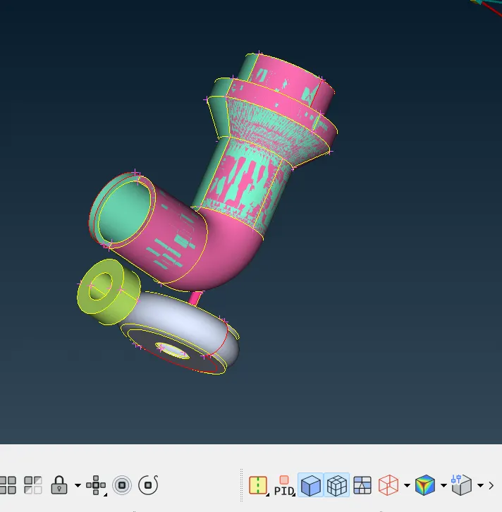
7. Here we can see that thegeometry is having glich in it.
8. To find out which surface is ocerlapping and not needed we will go for PID hiding by clicking on the glowing bulb off.
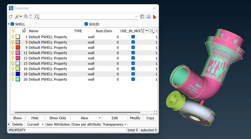
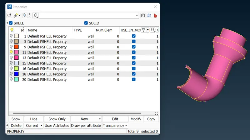
9. Here we can see that the geometry in the above image is the intersecting one which was showing up with the glitch and is incomplete.
10. Now we will delete this geometry with universal delete.
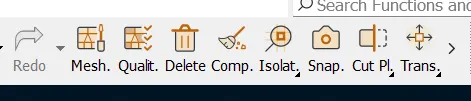
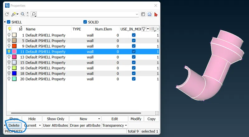
or we can delete the geometry with the Delete button in the Properties box.
11. Now click on ALL to get back the whole geometry.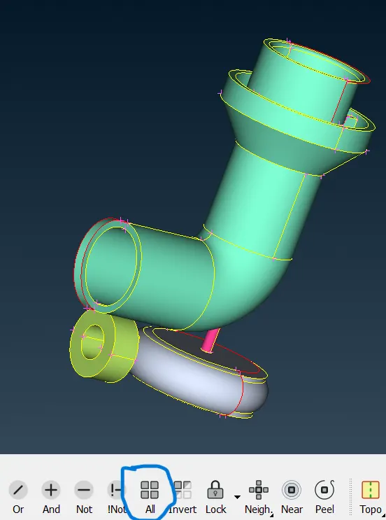
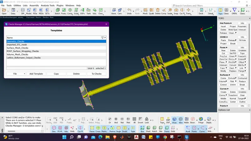
12. Now we will go for geometry check for checking out iff there are any intersects or no. of tripple and single cons.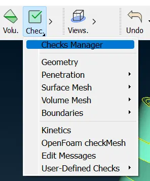
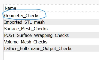
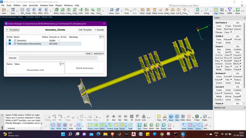
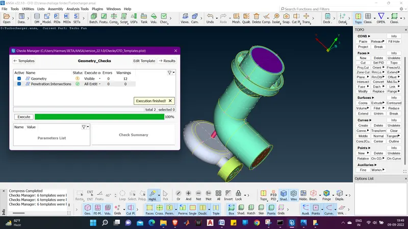
13. Double click on Geometry_Checks.
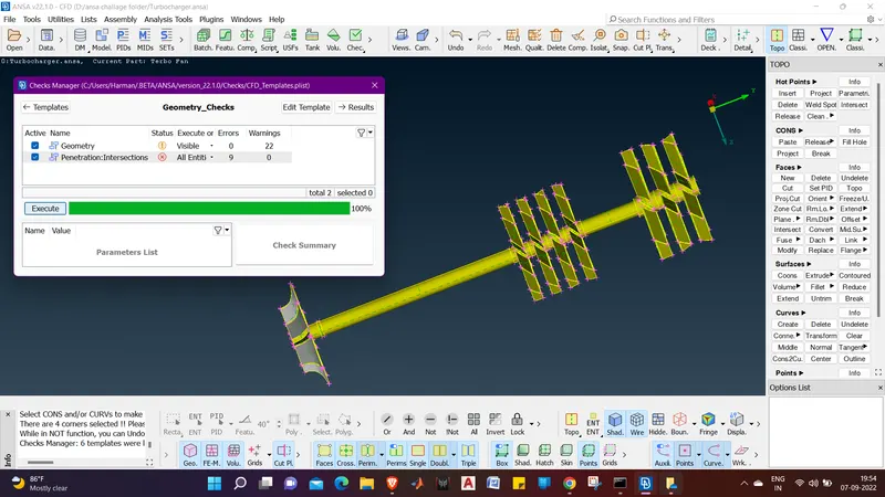
14. CLick on Execute.
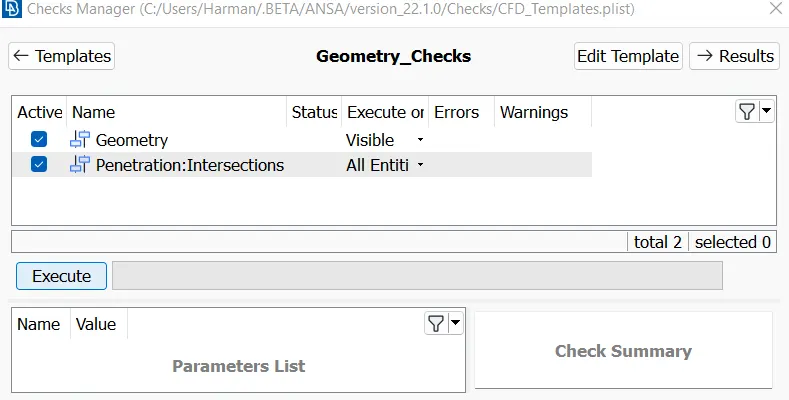
15. After executing we find Intesection Errors and Geometry Eroors.
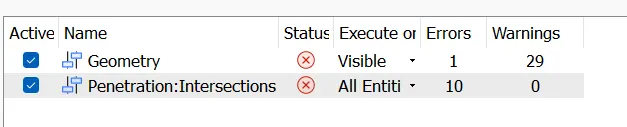
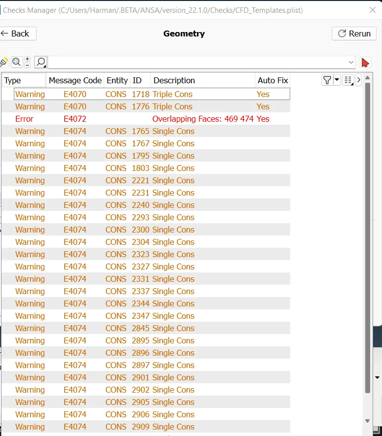
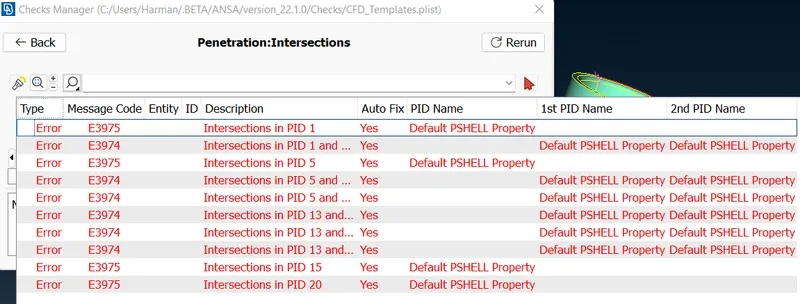
16. Now we will do the Geometry cleanup by deleting and adding faces.
17. First we will delete the outside faces which are not required and replace them with new face.
18. Now we can see that we have a surface coming out of the geometry having single coons. which seems not showing any importance, we will just delete the surface.
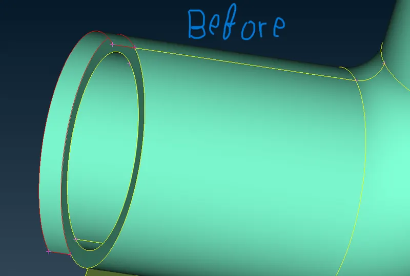
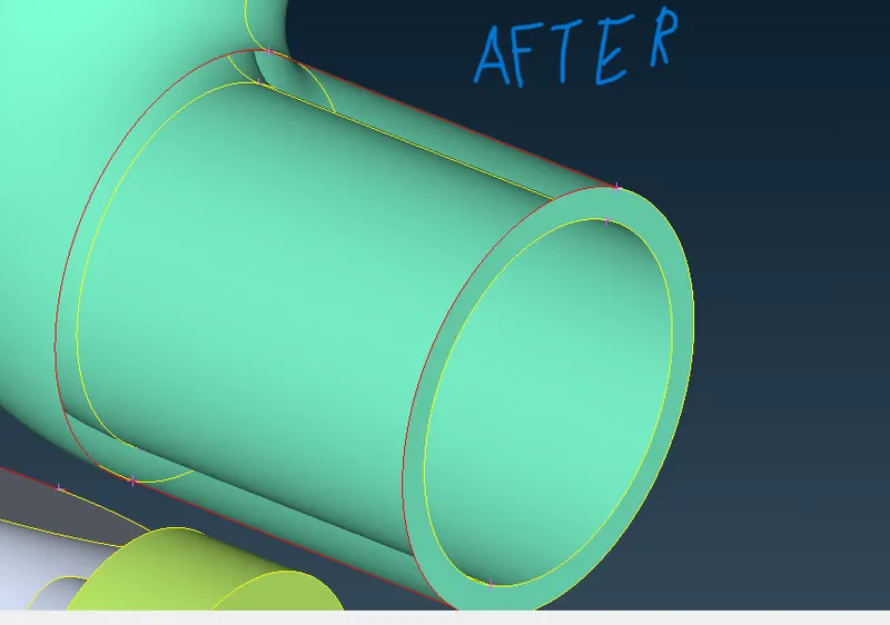
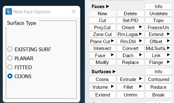
19. Now we will create a surface using NEW ( COONS ( LOOP )).
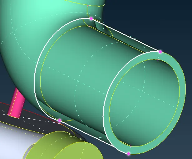
20. Now we will select the loop.
21. Now we will middle click and the surface preview will be created .
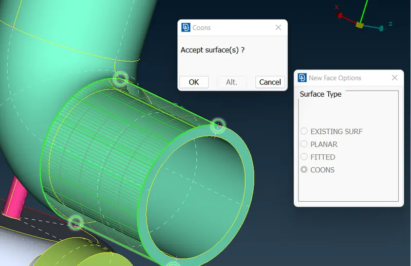
22. Cick ok and the surface will be created.
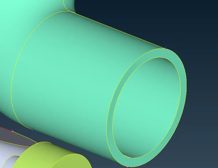
23. Now we will search for other geometrical errors.
23. we found a geometrical error in the turbo casing. 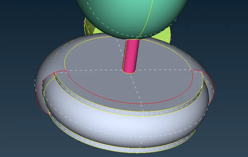
24. here we will use a new command to create surface.
25. First we will try to create a surface with NEW(Coons(loop)).
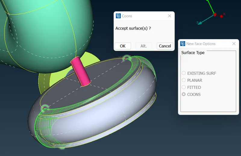
26. we can see the result we cant get a desired surface .
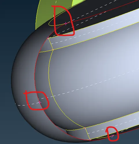
27. Here the problem is that the comand is taking a different path to create the surface. so we hae to create hot points to give the propper path.
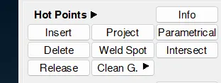
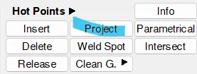
28. Now we will use parmetrical command in HOT POINTS tool box..
29. In parametrical commnd we can create a hot pint between two hot point of a coon bu giving a desired distance on the scale from 0.1-1 (percentage).
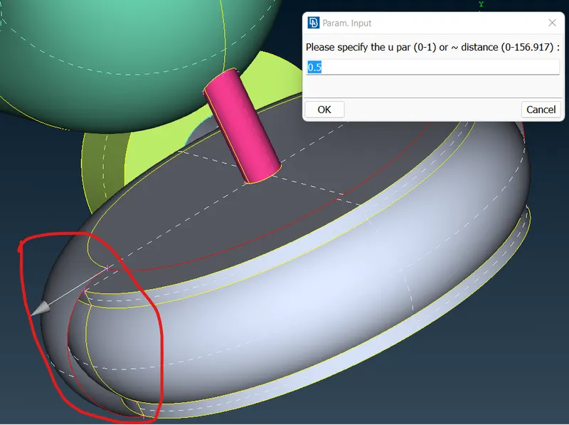
30.When we will click ok a hot point is created in btw the two hot points.
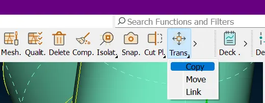
31. Now we will use The universal Transform command in which we will select copy as the transform tool.
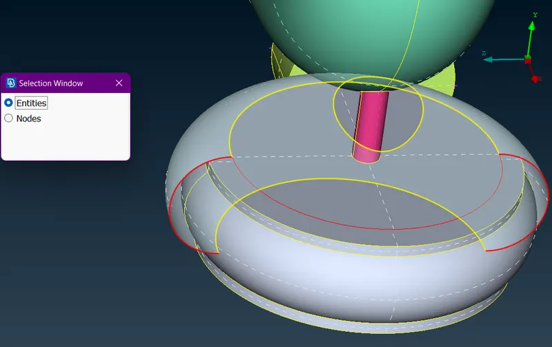
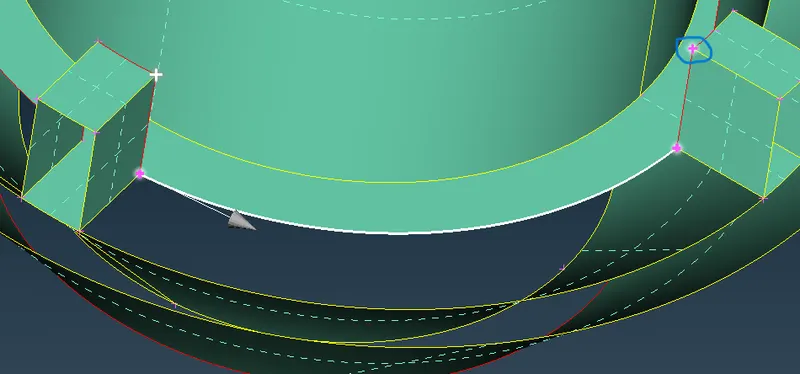
32. Now we will select entities in the dialogue box and select the surface we want to copy.
33. when we middle click we have a window pop up which shows different options, we will choose symmetry (mirror 3 points plane) and select the points .
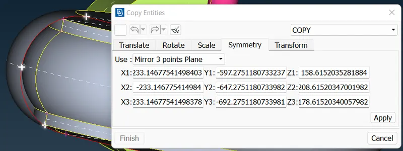
34. Now when we we click on apply a new window pops up. in this we only have to click ok, no parameters to be changed.
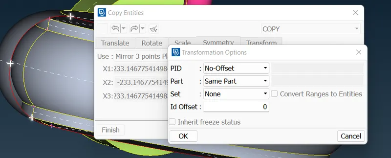
35. when we click ok the surface get coppied now click on finish and end the command.
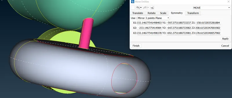
36. Now we can see that there is a red coon over the surface which should not be there after we created the surface. so we will fo for TOPO which will resolve the problem of red coon.
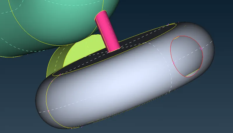
37. Now we vcan see a red coon on the surface again.
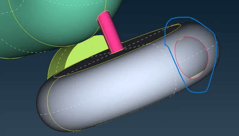
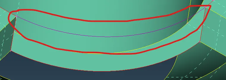
38. we will clear this coon by using FILL HOLE command.
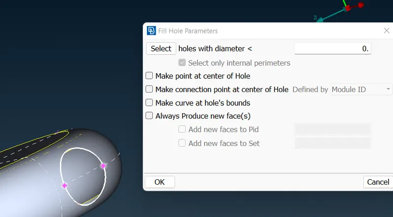
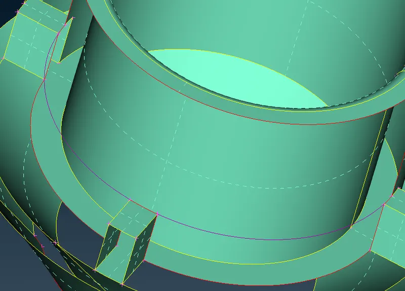
39. When we do the selection and click ok, the suface is created.
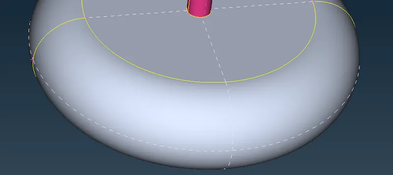
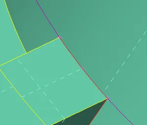
40. Now we will see for the next gemetry problem here.
41. here we can see that the surface is missing, so we will try creating a surface here.
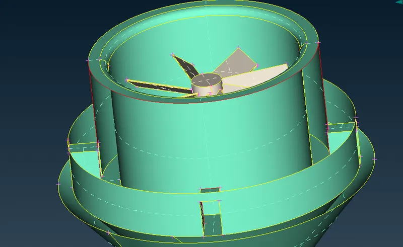
42. For creating the surface we need to hide other surfaces which are locking the view. and awitch to wire frame mode rto see the eroor too.
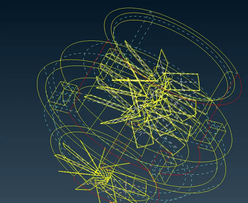
43. we can see here that we the red coon is present here so we have to create a surface to clear the error. we will try using NEW ( COONS (LOOP)) command to rectid=fy the problem.
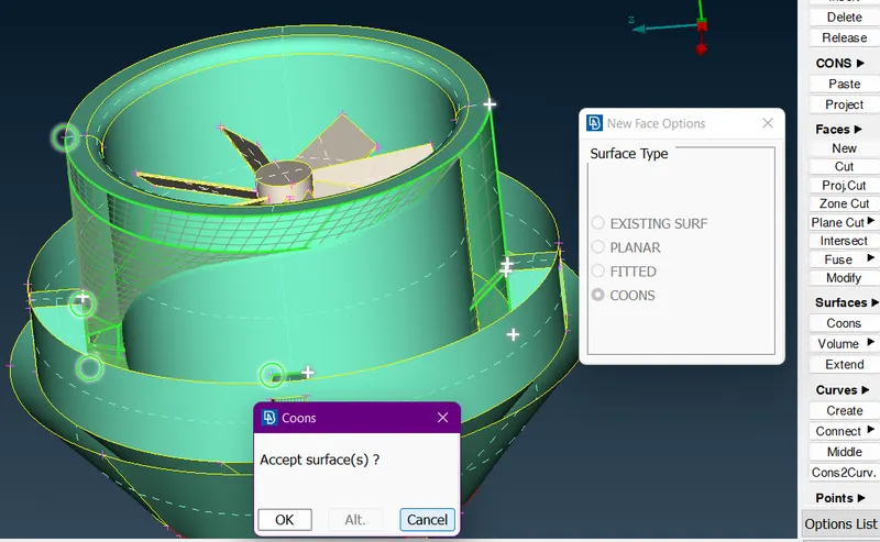
44. As we can see there is a distorted face forming in preview. so we can't go for this. We will try another method to deal with this problem.
45. We will try making cuves using a new command TRANSFORM . transform actually coppies a curve to the desired point.
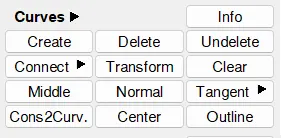
46. when we click on transform we will click on the cuve we want to copy.
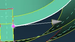
47. The arrow in the screen shows that we have to select in clockwise direction.
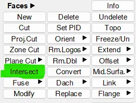
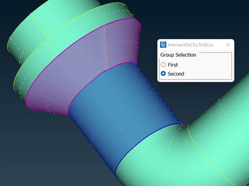
48. so we will start selecting from the ledft side. we will select the upper point above this coon on the left.
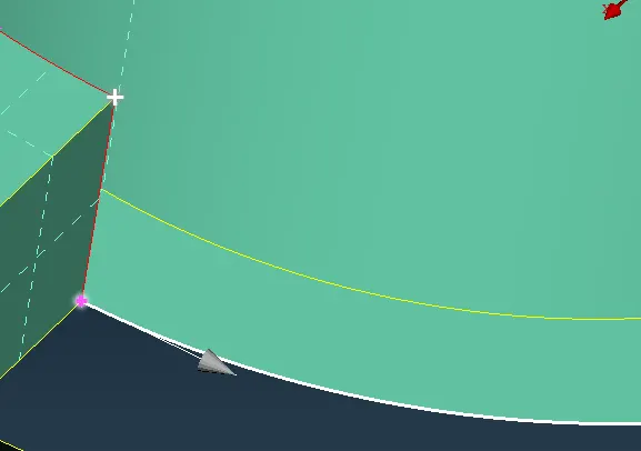
49. now we will select the second point opposite to it.
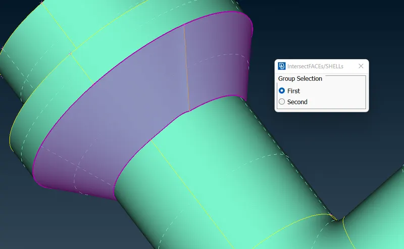
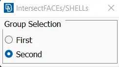
50. As we click on the point the curve is copied .
51. Now we will create the curve on the other side like this only.
52. Now we will create the hot points on the coon.
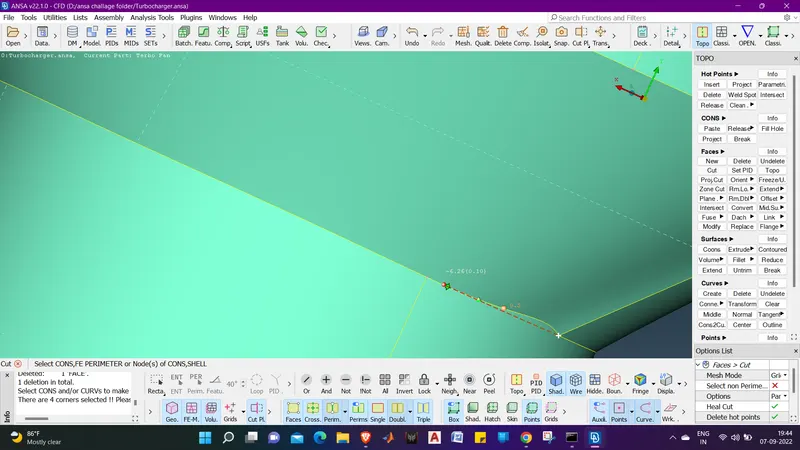
53. now the hot point we created we will project it on the upper coon.using project command.
 .
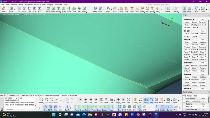
.
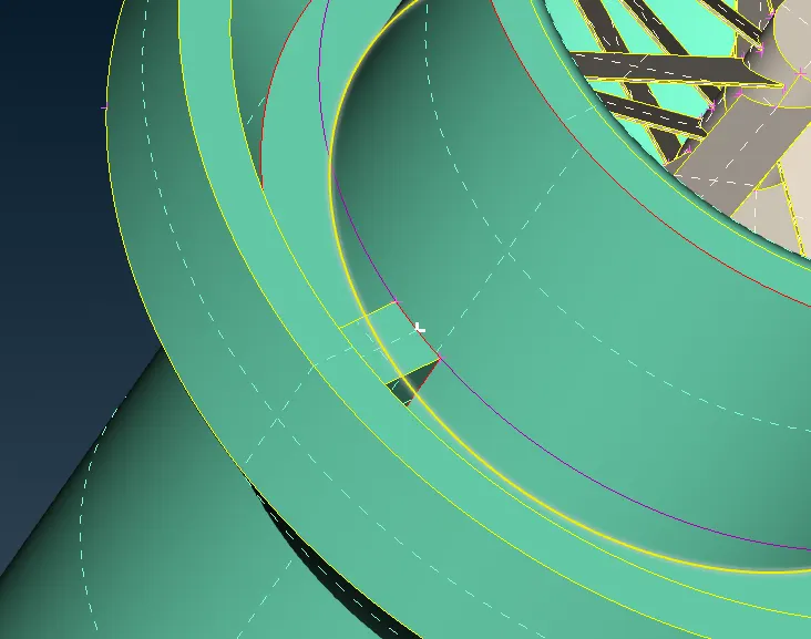
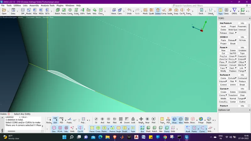
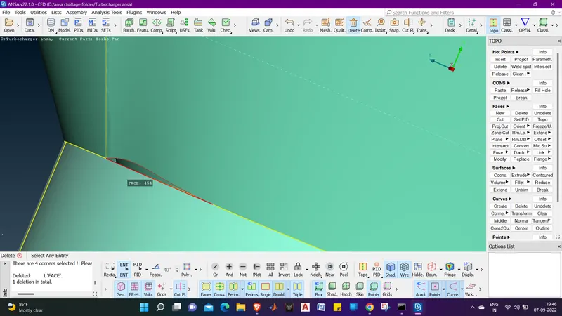
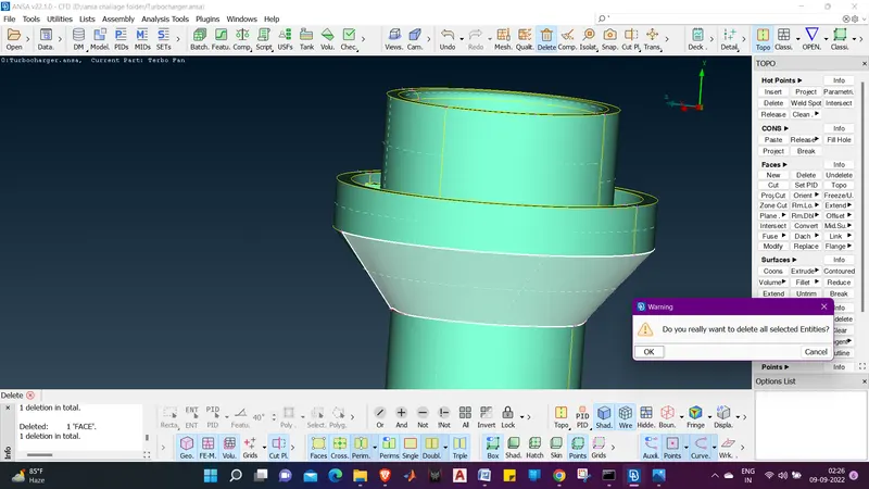
54. when we select the upper coon it get highlighted and the hot point is created.
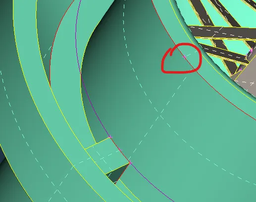
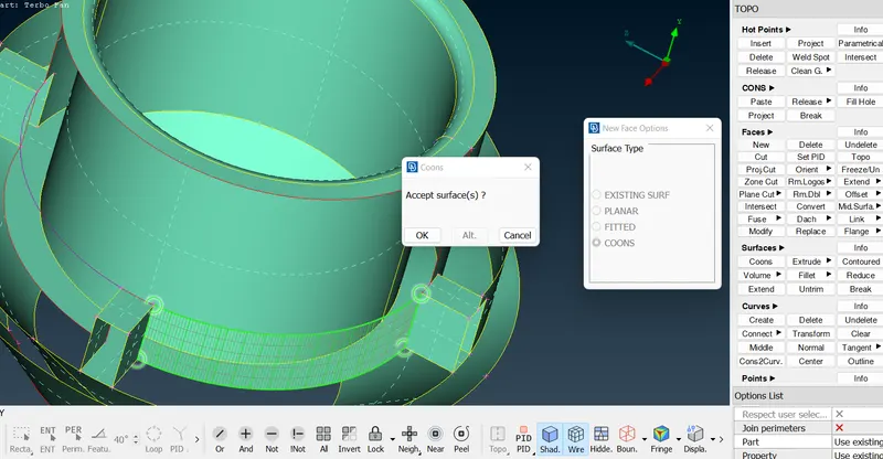
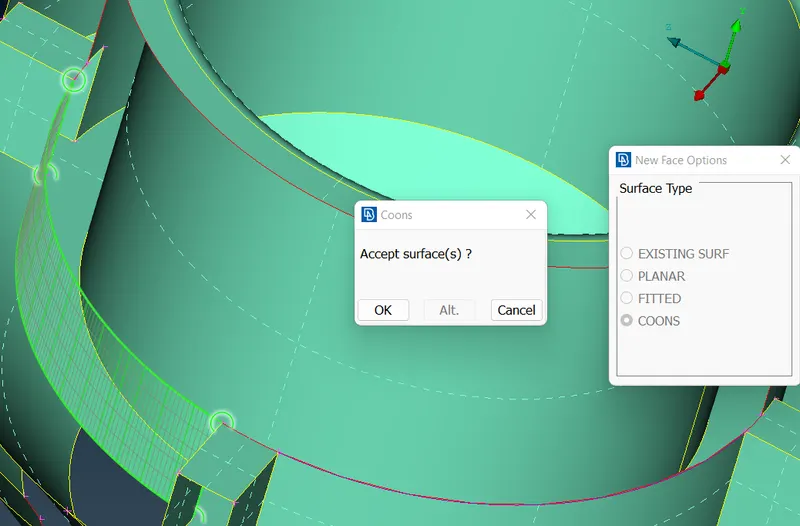
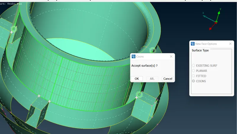
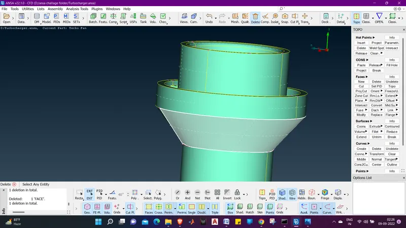
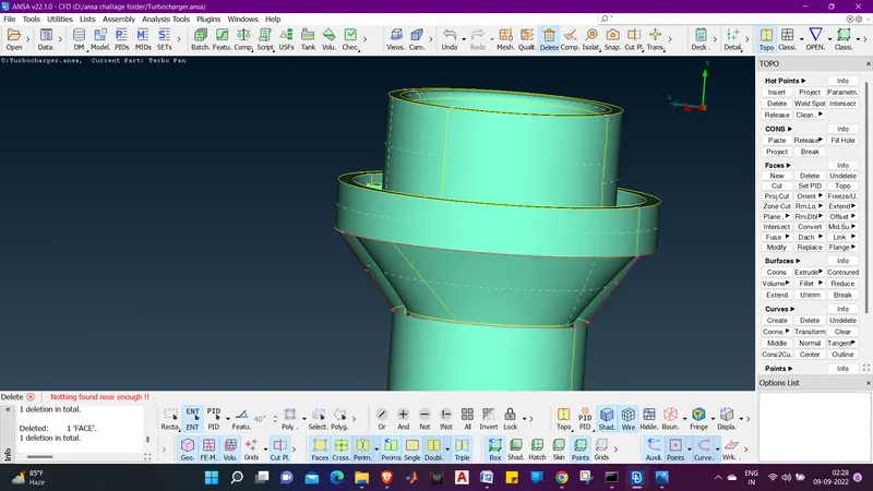
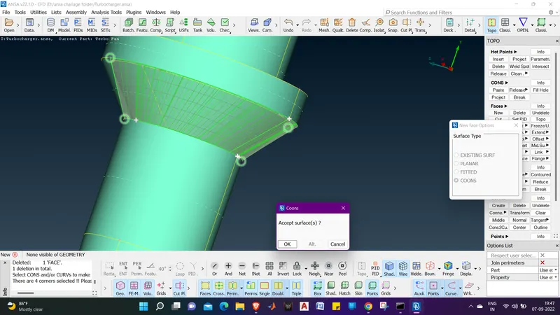
55. now we will make surfaces using NEW ( COONS (ENT)).
 .
.
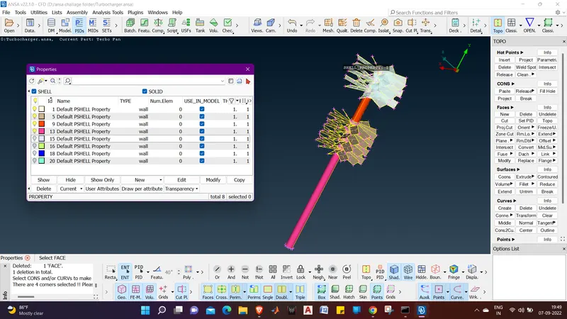
56. all the surfaces creaed here .
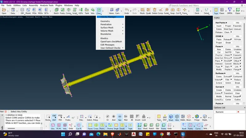
57. we will do all
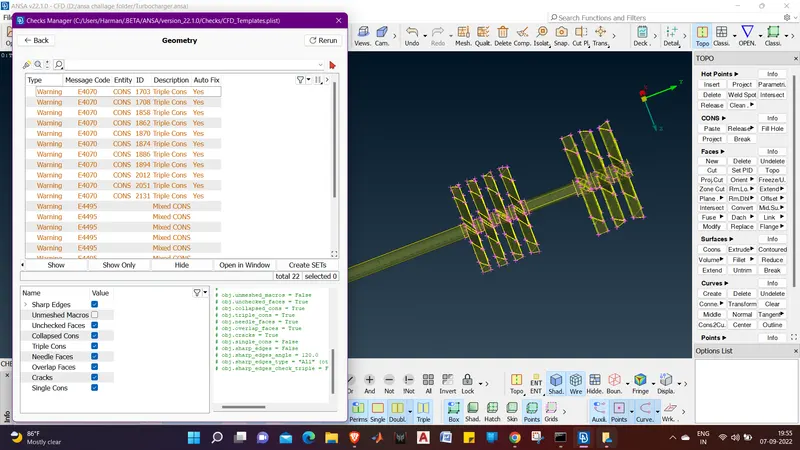
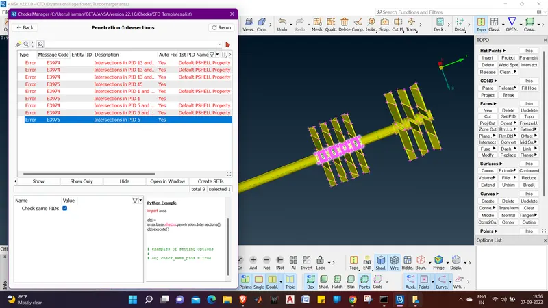
58. we will hide all other PID except the Impeller casing.
59. here on the outer surface we can see a unebven surface.
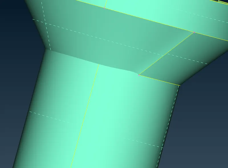
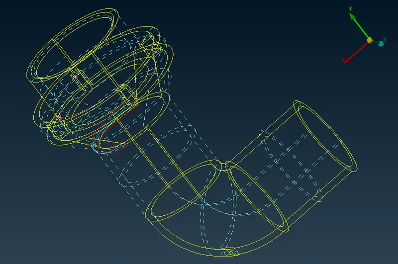
60. the uneven surface in wireframe shows as an extra face.
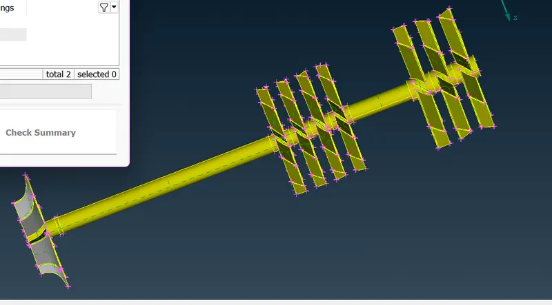
61. so we will use a new command INTERSECT.
62. this window pops up when we click on insert button which shows 2 option first an second.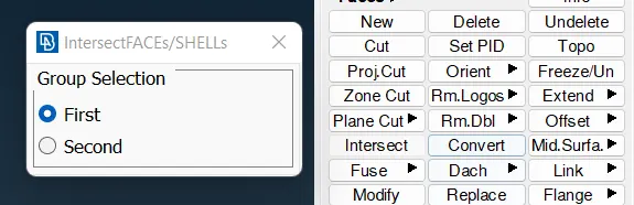
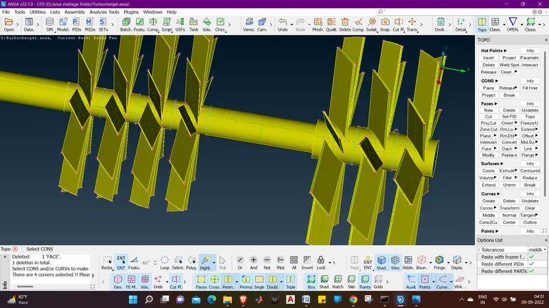
63. In first we will select the upper surfaces an dthen click on second to select the other surface intersecting.
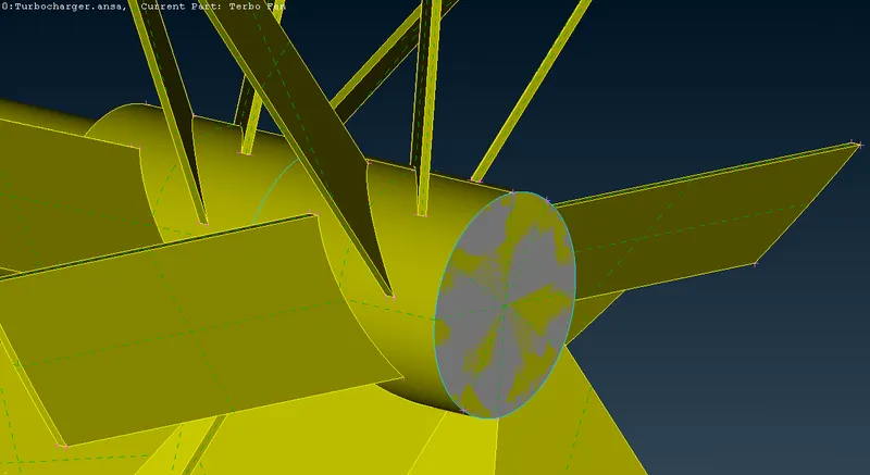
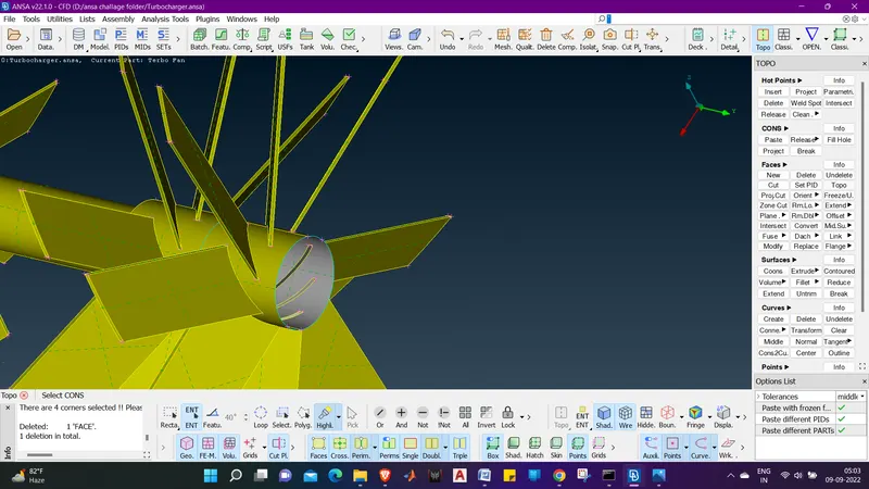
64. Now we will will middle click and a box will appear which will contain DELETE, KEEP and CANCEL button. we have to only keep and delete surfaces we want in the geometry.
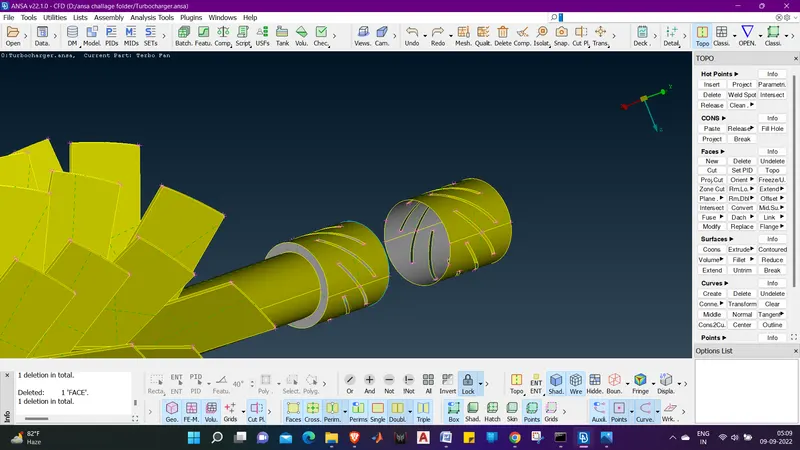
65. Now we have the final geometry after deleting and keeping body in geometry but we can still see some uneven surface.
66.Now we will try to modify this surface by making a cut on this surface using FACES(CUT) command .
67. As we have projected a cut on the surface and when we press middle button, the cut is created.
68. now we will do this on the other side too.
69. Now we will use universal delete to delete these unwanted surfaces .
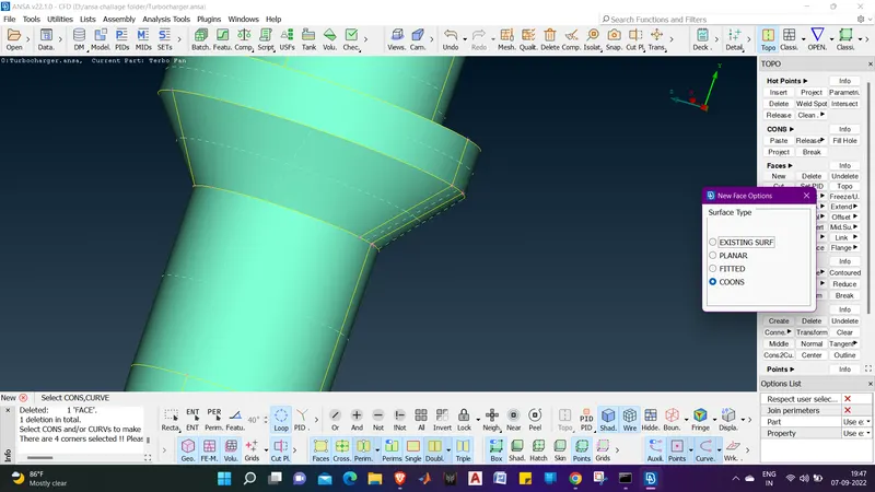
70. Now we will create a surface in the open area using FACES(NEW(COONS(LOOP))).
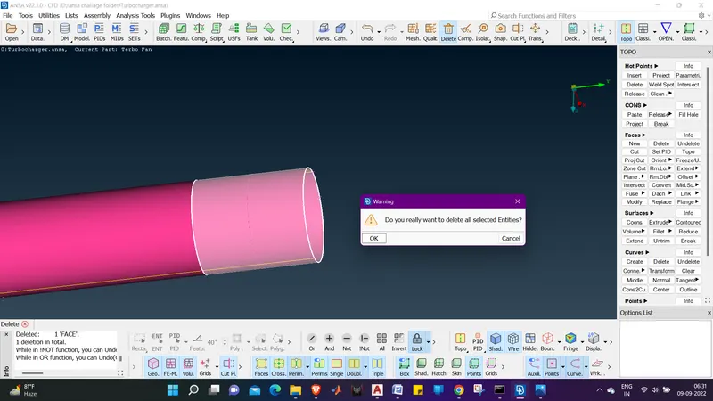
71. we will now click loop and the surface showing is perfect. so we will click okso surface is properly created without any uneven shape.
72. now we will go for internal errors.
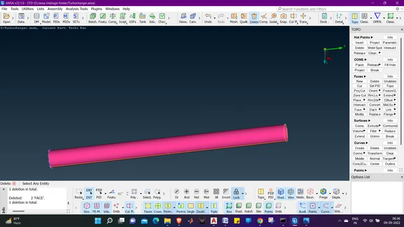
73.we will show the inmpeller blodes &shafts and hide other PID.
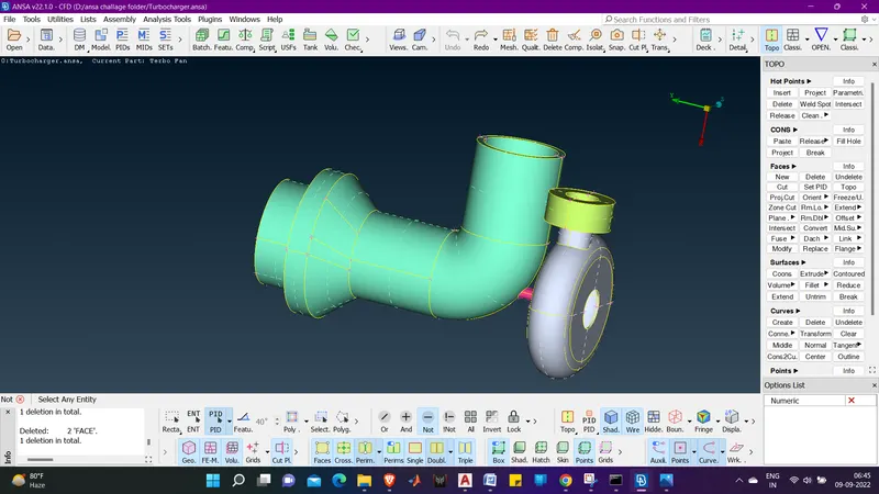
74.we will go for the geometry check.
75. In the geometry check we found many eroors . And when we check in the geometry eroors, there are lot of errors present.
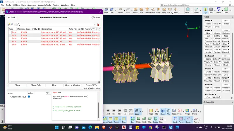
76. And in Intersection errors we are having many errors too.
77. Now we will try to resolve these errors.
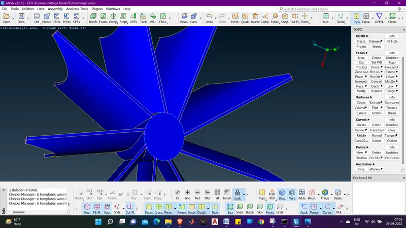
78. As we can see in the image it doesen't show any errors visually.
79. so now we will do a topo, now we can see the triple coons are there.so we will rectify this error.
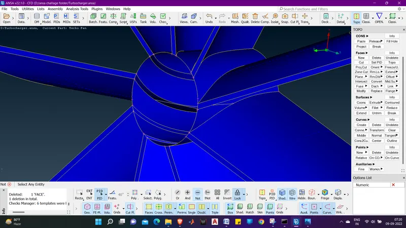
80. we will hide the surfaces and check whether there are extra surfaces.
81. we can see that there is an overlapping surface. we have to delete it .
82. we can see that the tripple cooon is stil present, that means the face we hiden also contains a surface. we have to delete that surface by hiding the middle one and deleting the extra face.
83. and one more thing put lock whenever we hide other components. it helps in getting back to the point that where we ledt even if we do all it won't allow the hiden component to shpow back again.
84. we can see that the tripple coon is not there. like this we have to do all others.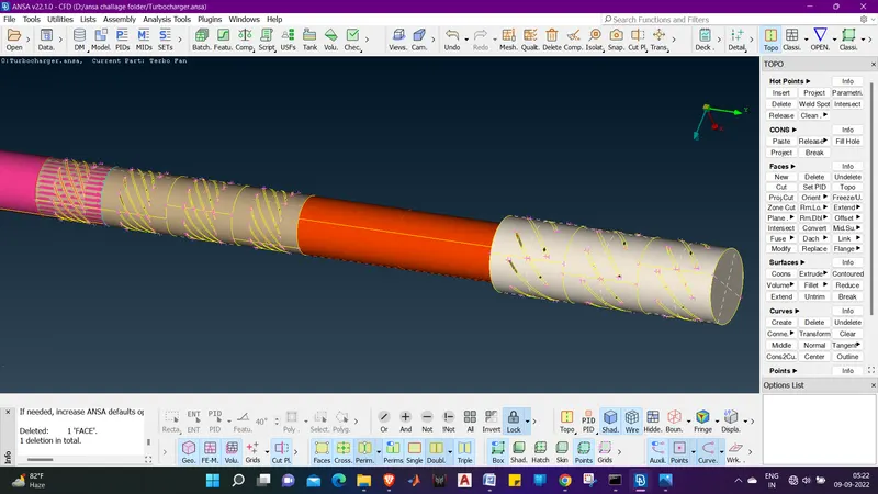
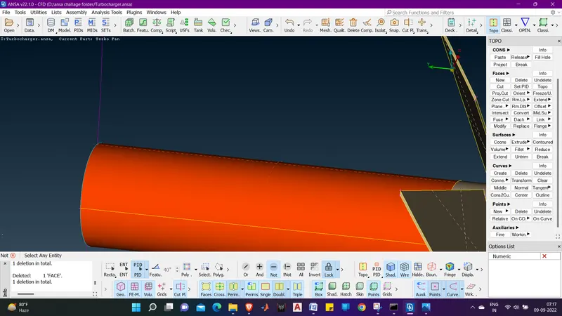
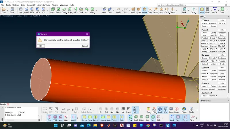
85. As we can see all the tripple coons are removed in the same process, but one is left,.
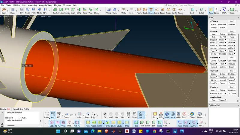
85. we will just project coons on the pink part using COONS(PROJECT).
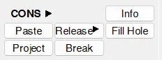
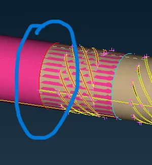
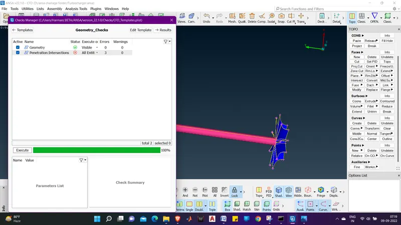
86. we will project the coon on the pink surface.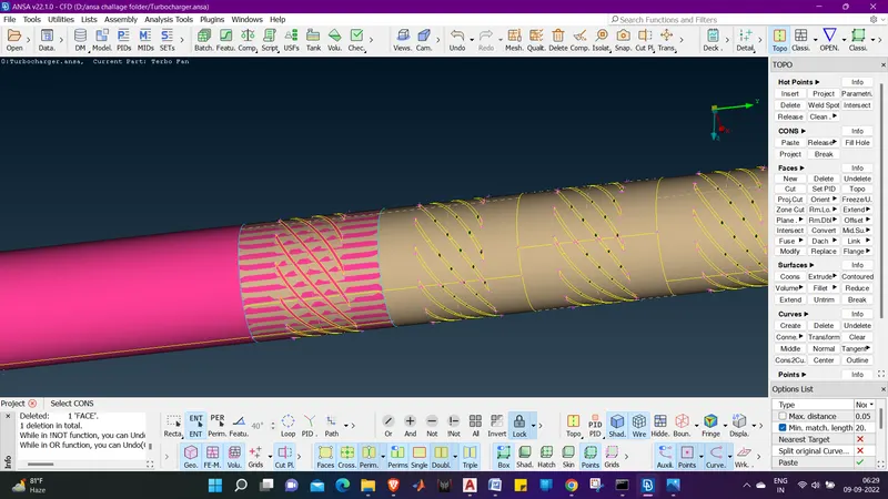
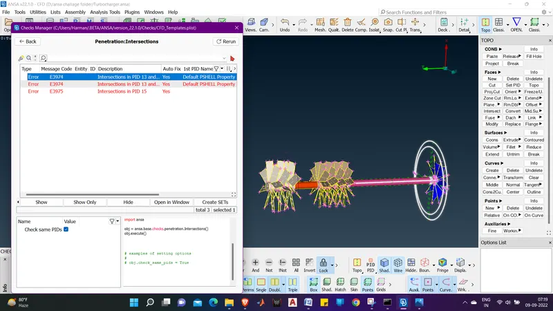
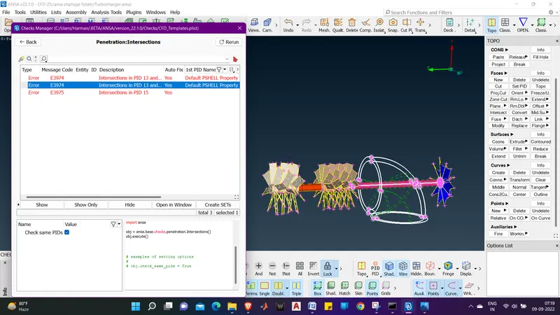
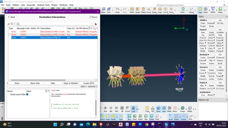
87. Now we will hide all the other PID except pink one.
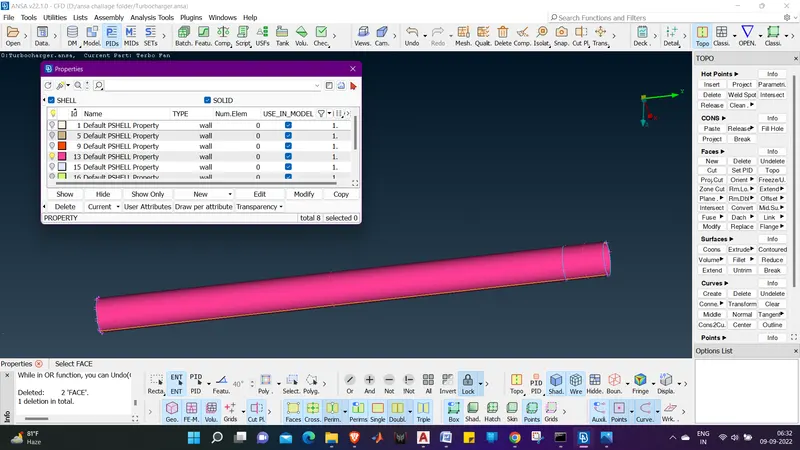
88. now we will just delete the extra surface using universal delete.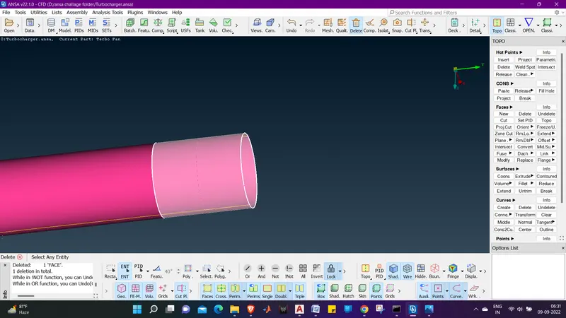
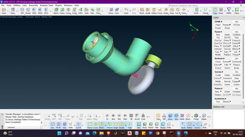
89. when we click ok the surfaces gets deleted.
90. Now we will do ALL.
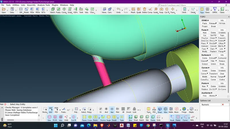
91. we will again select PIDs to hide.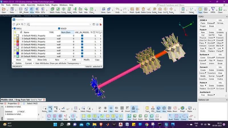
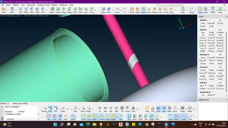
92. we will do topo now .
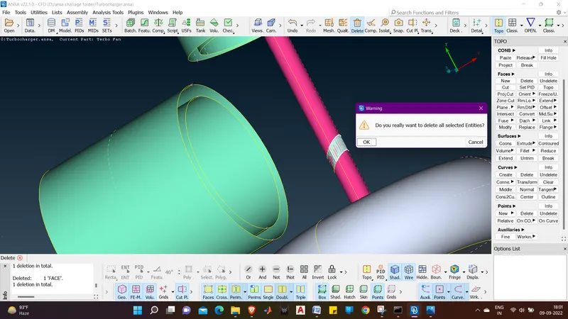
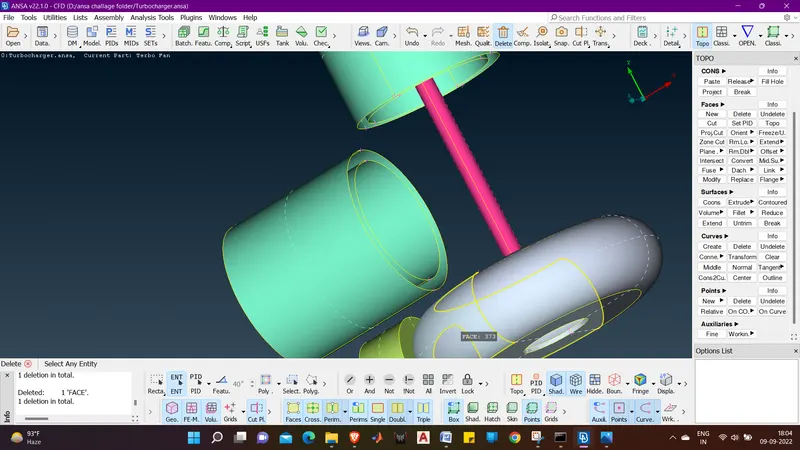
92. we will now again go for geometry check for finding out the remaining errors.
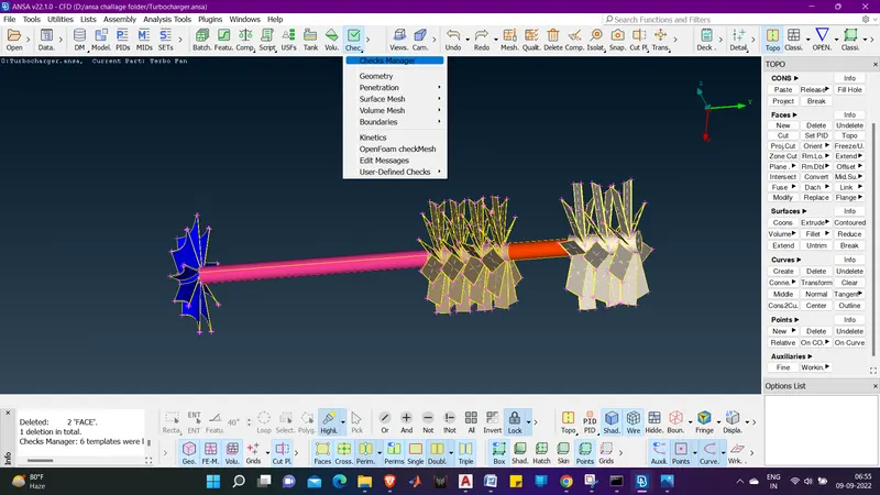
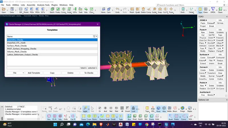
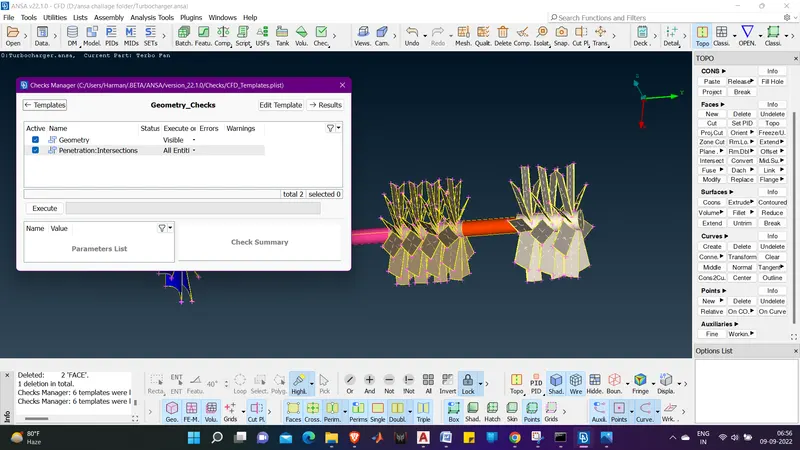

93. Now we can check that there are some warnings in geometry section and errors in the Intersection section.
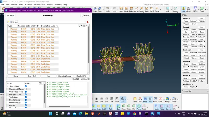
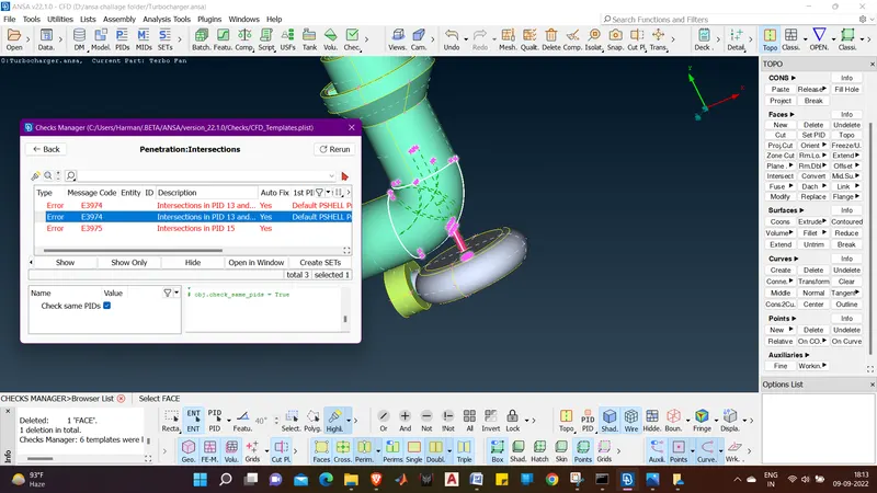
94. now lets check for the solutions we can give to correct the geometry.
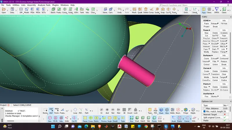
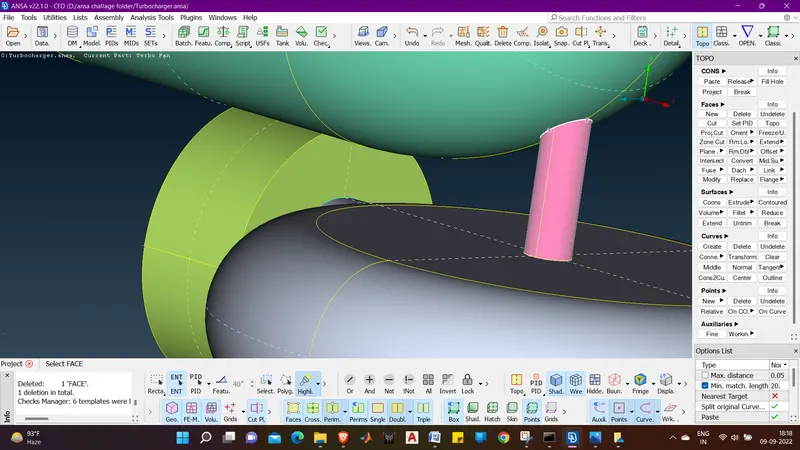
95. we can check here there is blue coon present on the surface , but as its all faces are connected we have to cut the surface in different parts,
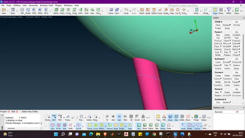
96. We will create cut on surface using FACES(CUT).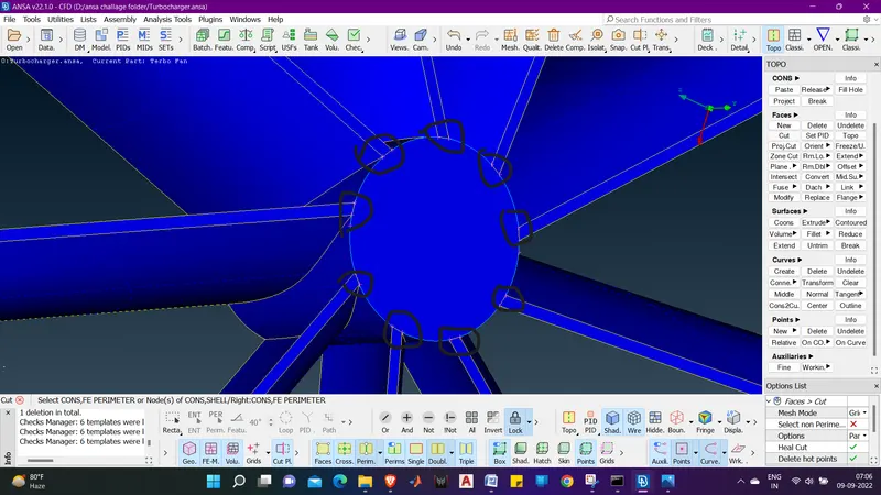
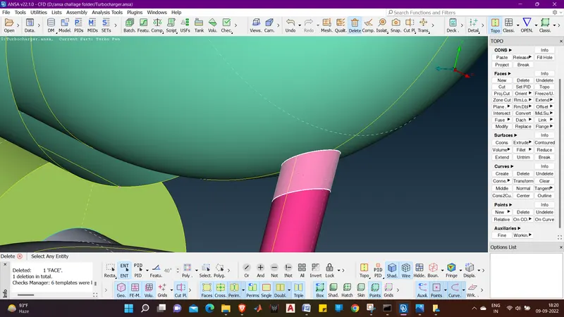
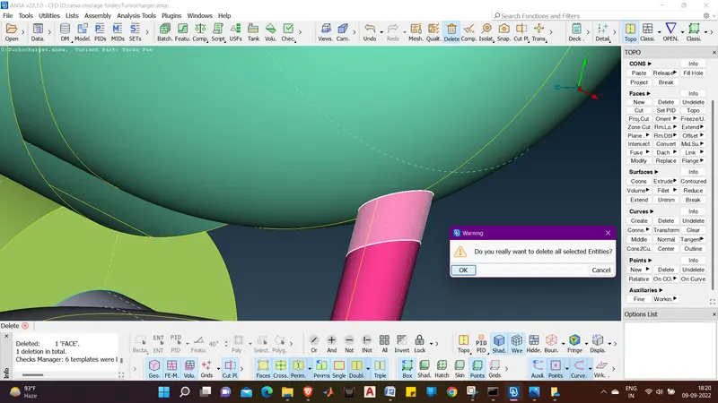
97. now we can delete the face causing tripple coon using universal delete.
98. now we have one more problem of intersection above we hace project a coon on the surface using project in cons.
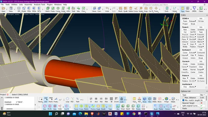
99. hiding the surface using NOT.
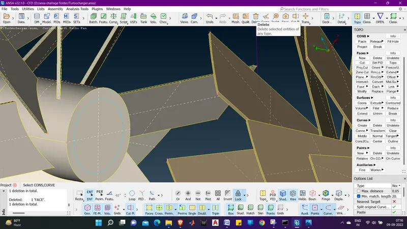
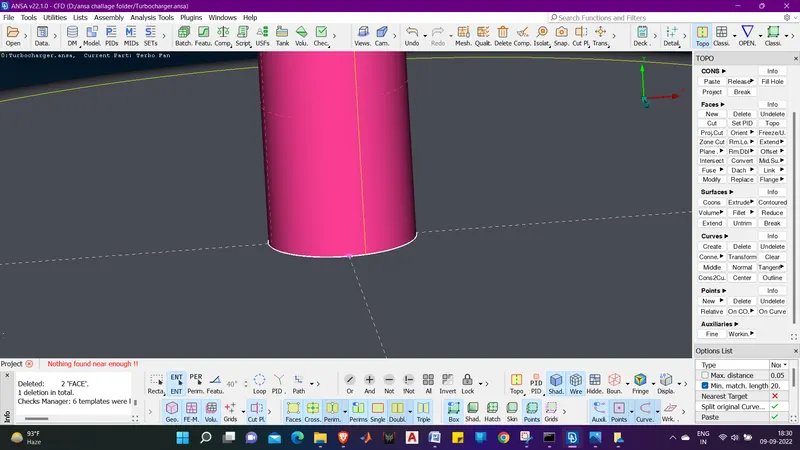
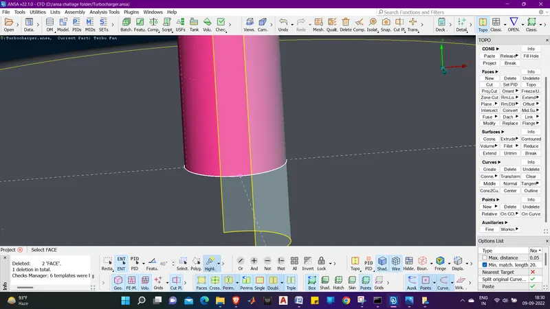
100. deleting the surface using universal delete.
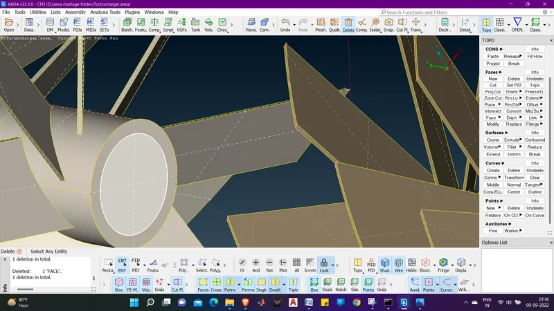
101. we will unhie the shaft.
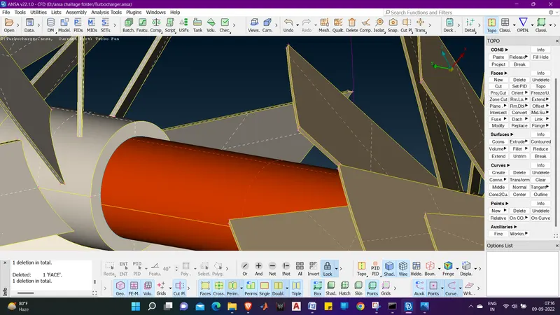
102. now we have to delete other surface by hiding the blades shaft.
103. NOw we can see there in no blue coon present, here intersection eroor is cleared.
104. now we will go for geometry check.
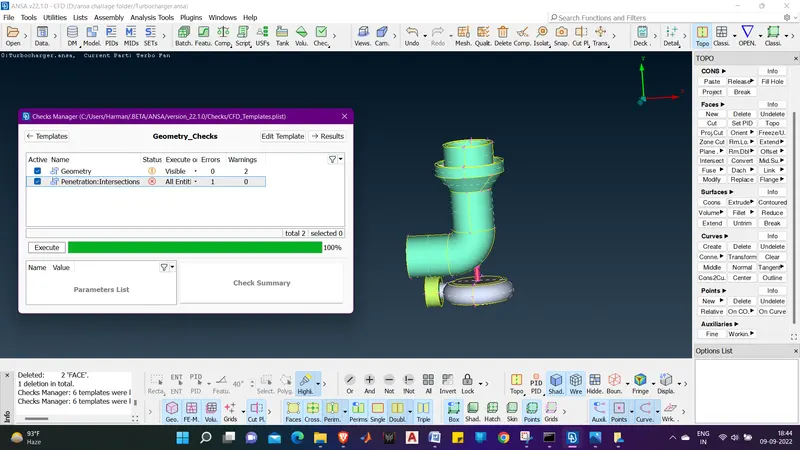
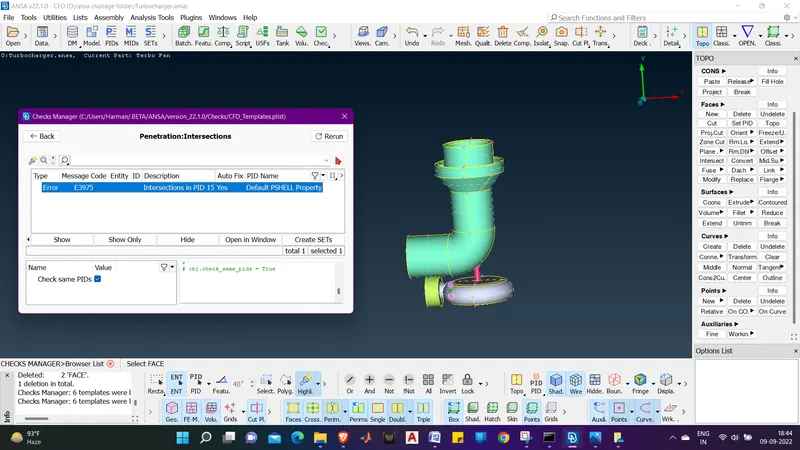
105. gemetry check is showing 3 penetration errors.
106. For clearing up allthe intersection eroor we have to show all the parts.
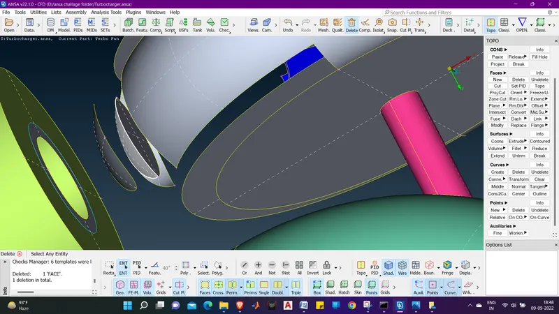
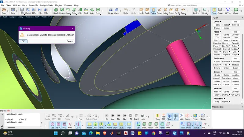
107. so we will unhide all teh PIDs and we will have the full model back on screen.
108. we will first clear the errors for turbo casing.
109. we can see we have an overlapping shaft inside the compressor casing.
110. We will now use universal delete for deleting the green surface.
111. we will click ok and the surfaces will be deleted.
112. Now we will check for the intesection eroor again after making all surfaces unhiden.
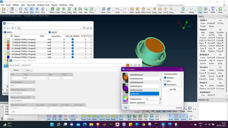
113. we will now do the geometry check again we can see that the intersection error is not resolved. so we will again try to resolve this intersection error.
114. we will project coons on the shaft. to split the surface and delete it.
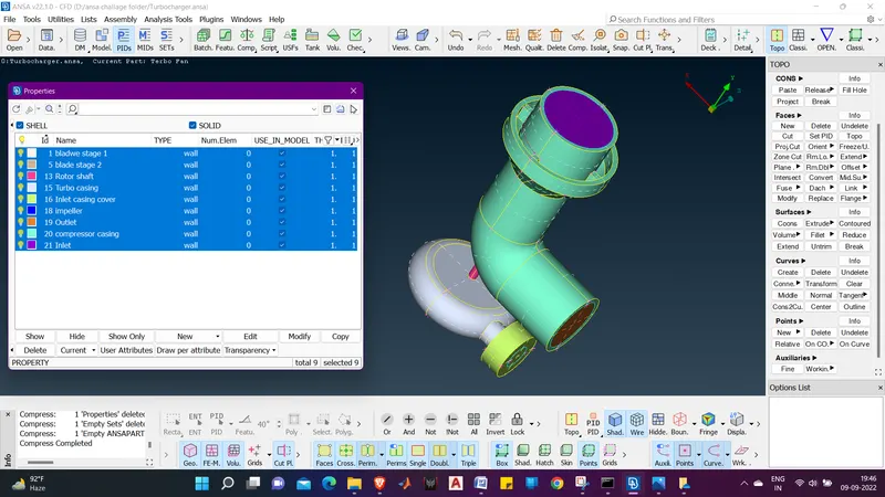
115. as we can see the coon is projected on the shaft. we will do it for the upper coon too.
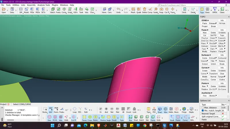
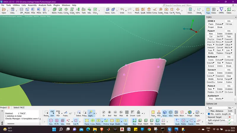
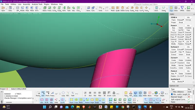
116. now we will universal delete to delete the shaft surface ass we are conserned with the internal volume so if we delete the surface it will not affect the internal colume of the compressor cassing.
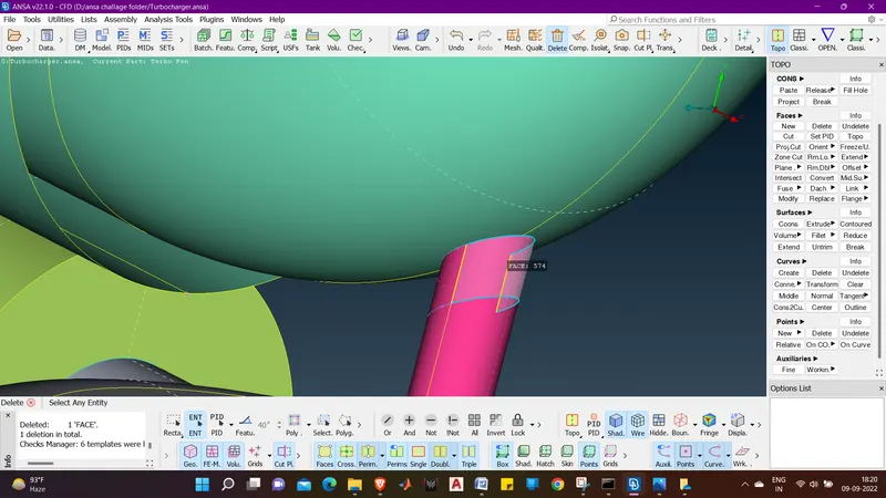
117. now we will go for turbo casing intersection error with the Shaft.
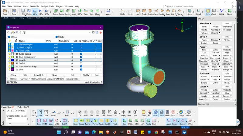
118. we will do the same thing with the turbo casing shaft as done above in the compressor cassing.
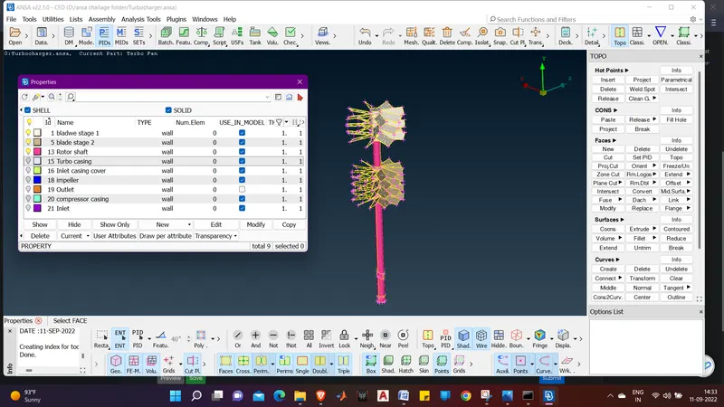
119. we will project coons to split faces anf delete them with the univesal delete option.
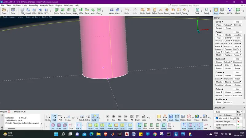
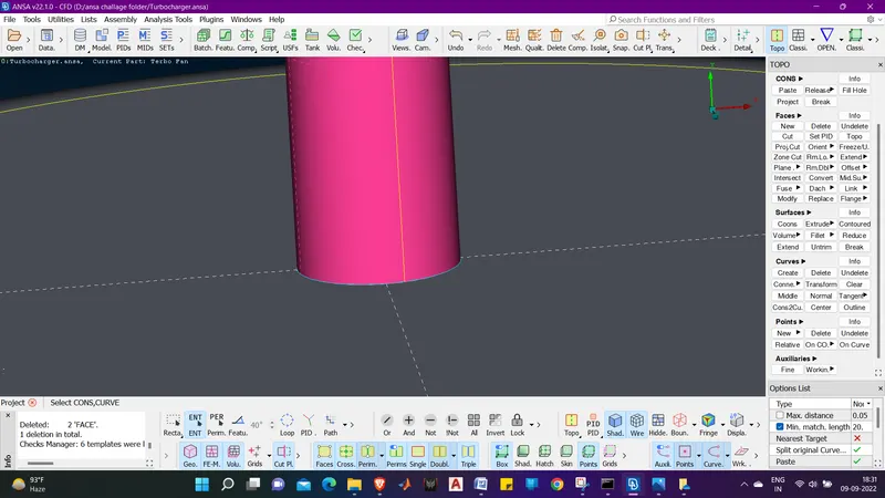
120. Now we will hide the top surface off turbo casing.
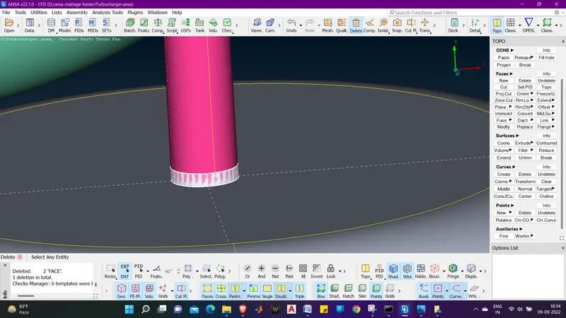
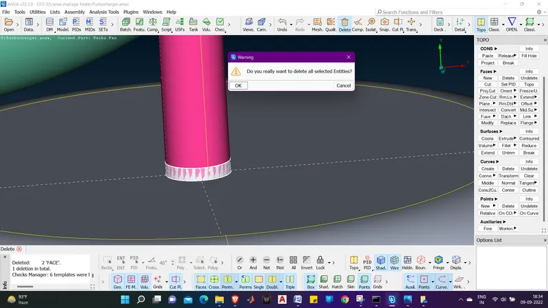
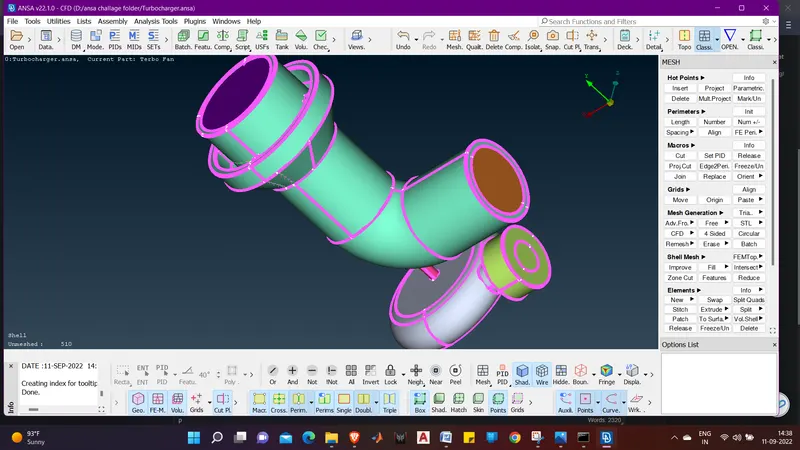
121. we will delete the overlapping surface using universal delete.
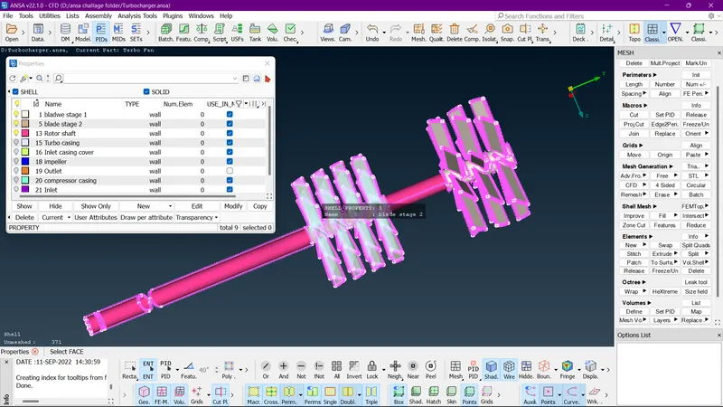
122. next we will project the coons on shsft from the torbo casing internal surface.
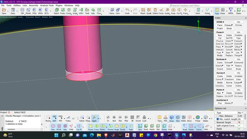
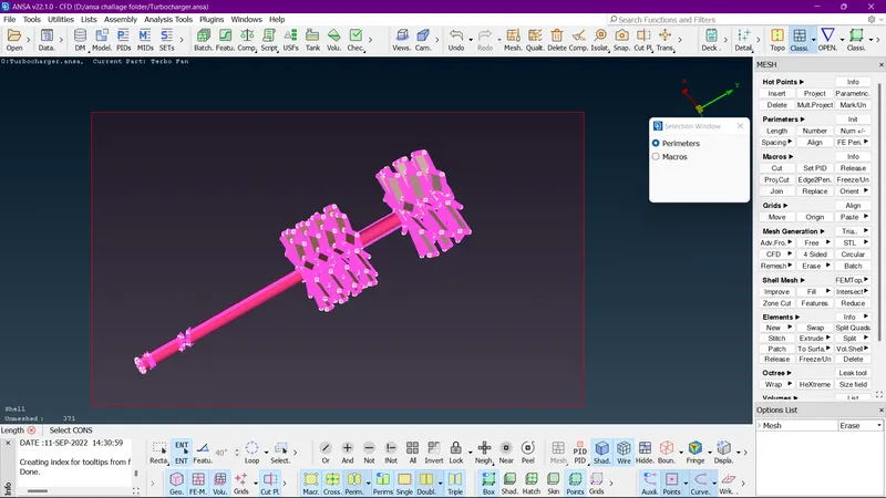
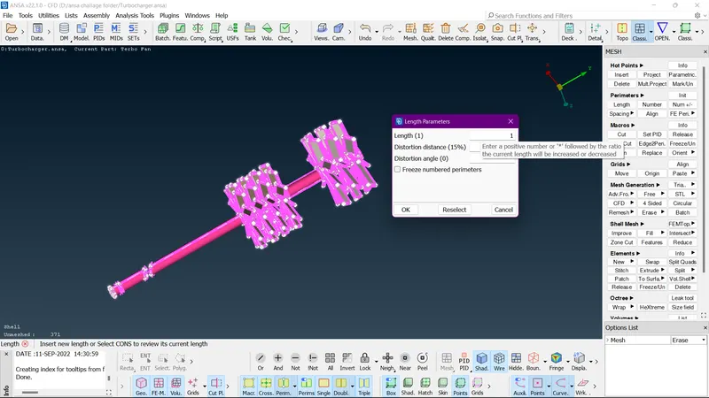
123. next we will try to delete the shaft surface using universal delete option.
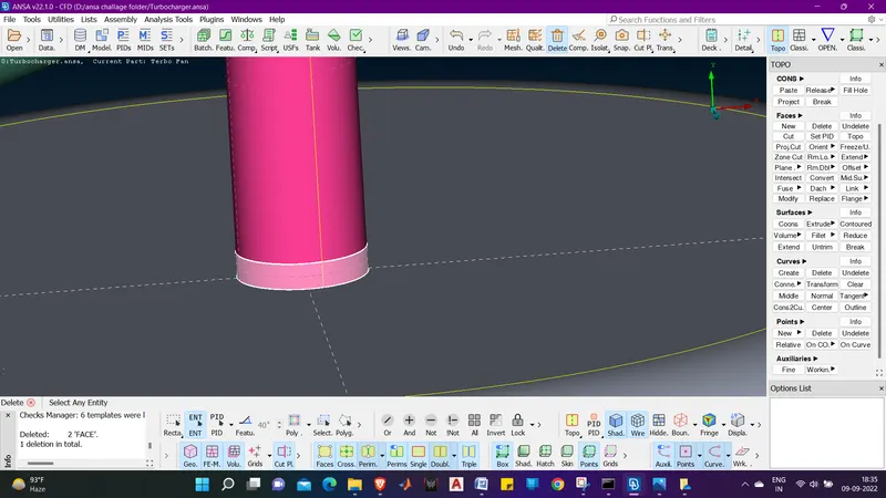
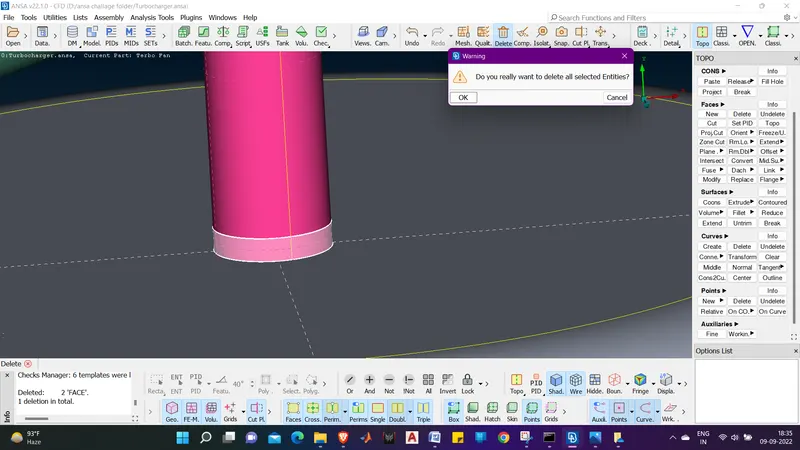
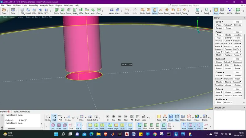
124. we will show all surfaces and again do a intersection error check.
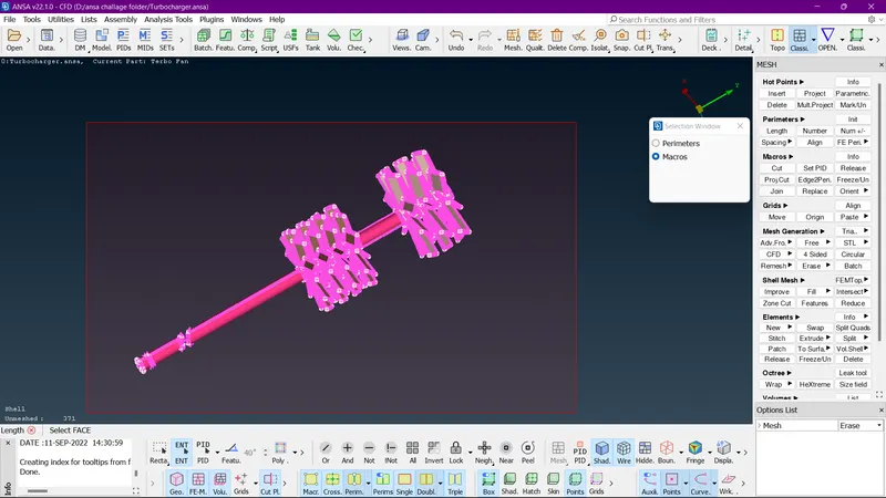
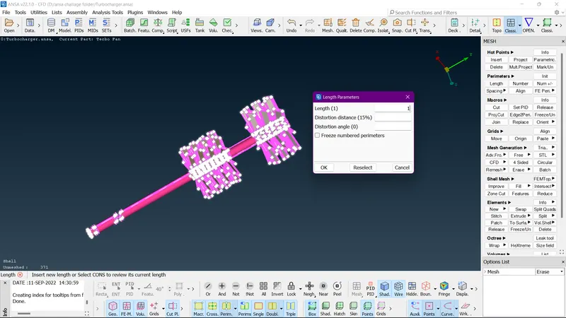
125. we can see that we have resolved 2 intersection errors and one is remaining and that inside the turbo casing.
126. we will hide turbo casing surfaces to delete the surfaces using universal delete option.
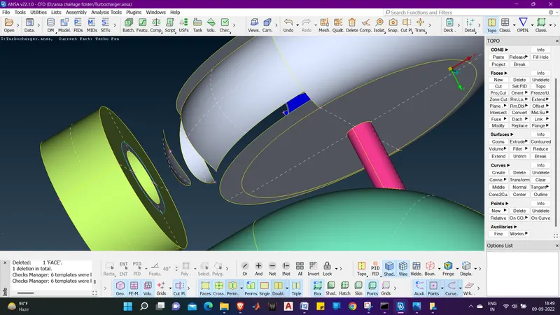
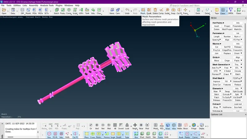
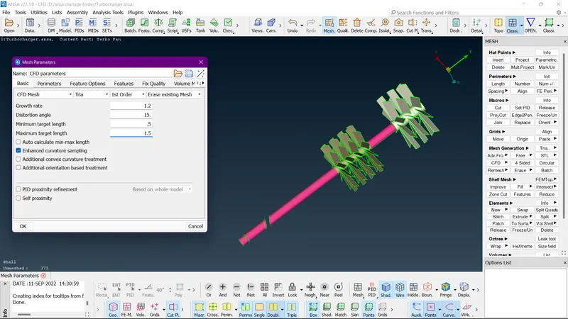
127. as we can see the extra intersecting error is resolved lets do a geometry check again will all component.
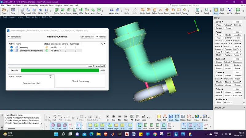
128. No inersection erroe is pressent now but 2 warning for geometry errors are showing. lets chaeck whats it about.
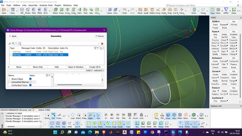
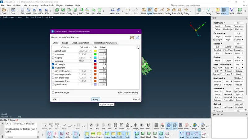
129. we have seen that there are triple coons heighlighting at the outlet of turbo casing. Here these tripple coons are necessary so np need to delete them.
130. now we have to make the geometry inlet and outlet close using NEW(planar) .
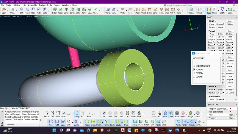
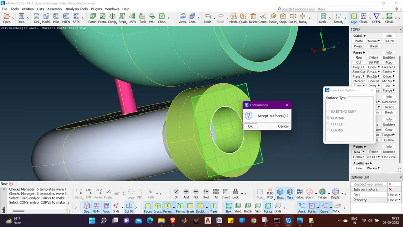
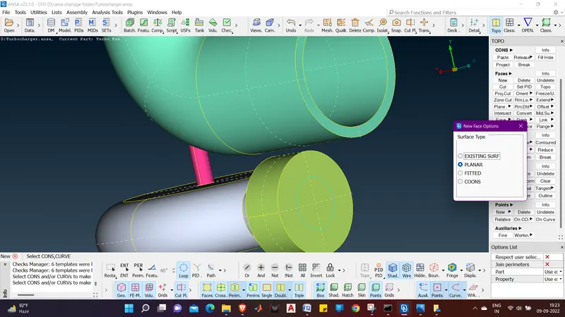
131. LIke this will Close all the holes.
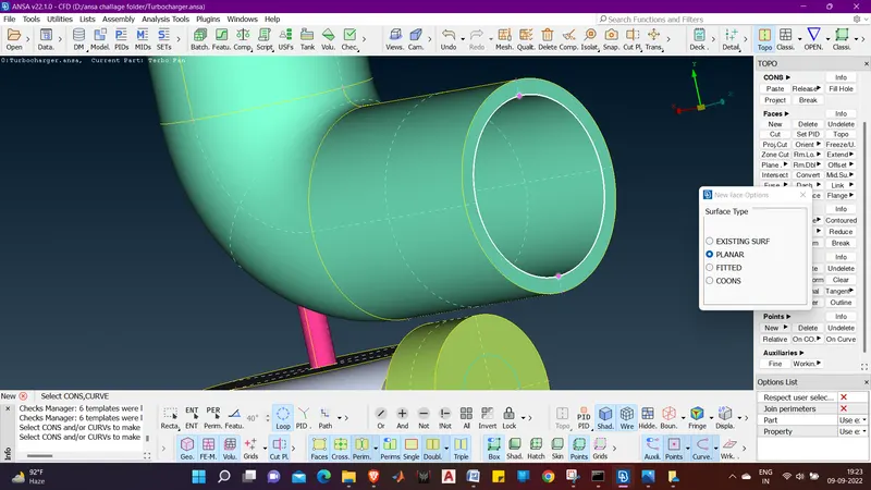
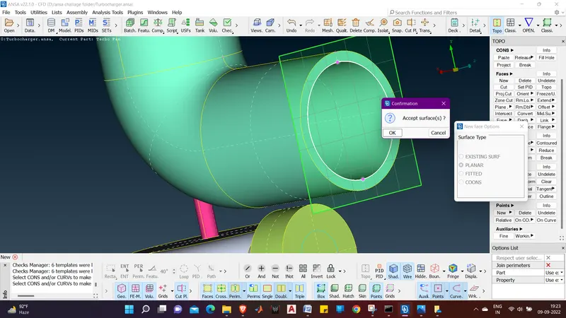
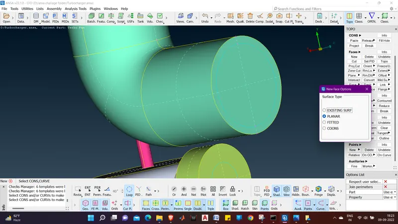
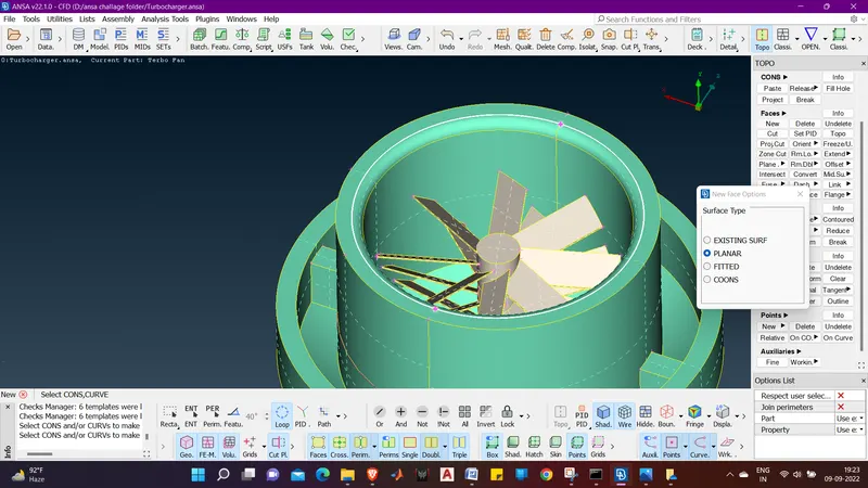
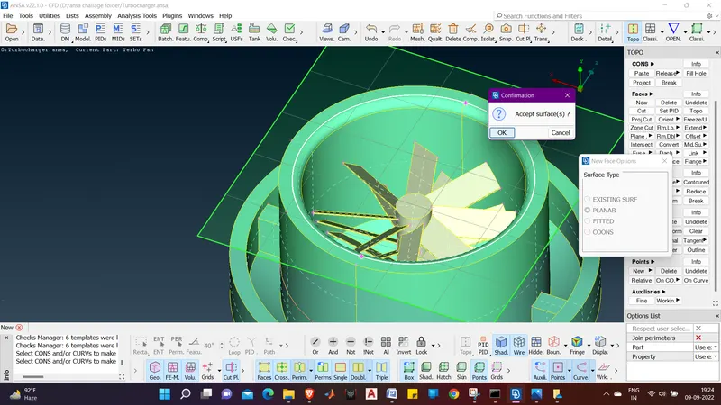
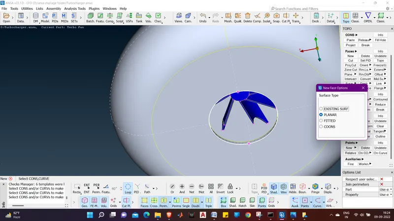
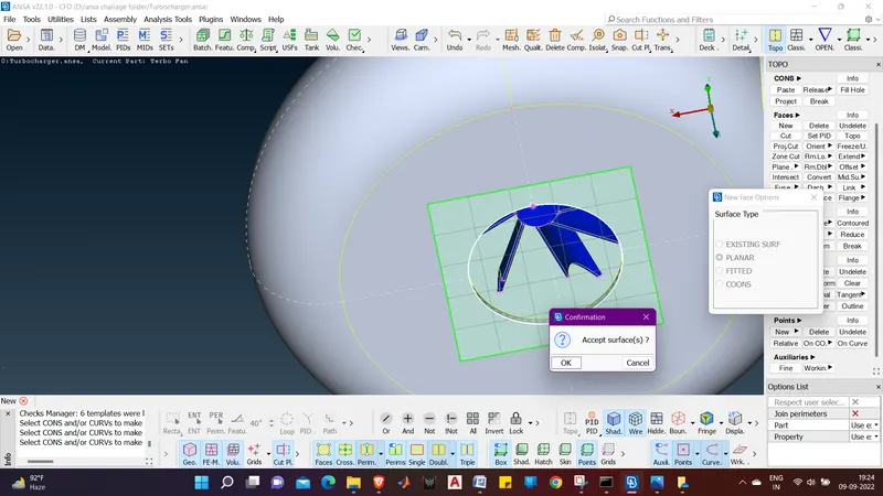
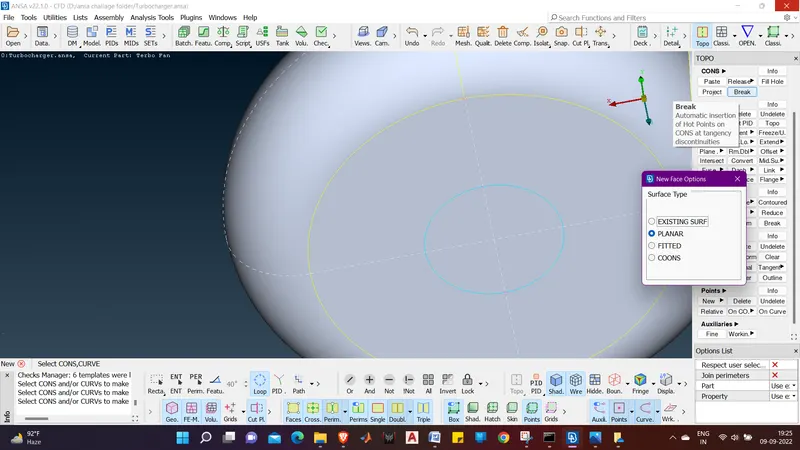
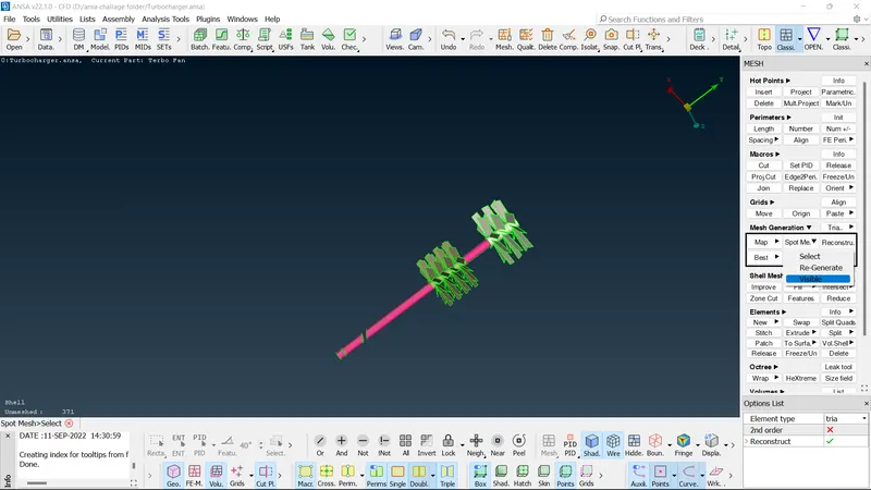
132. Now we will assign PID name and assigning PID Geometry. .
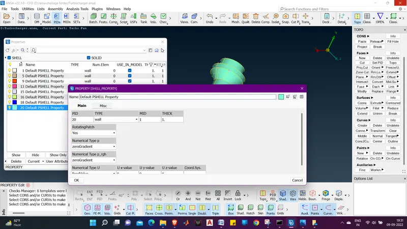
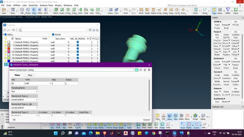
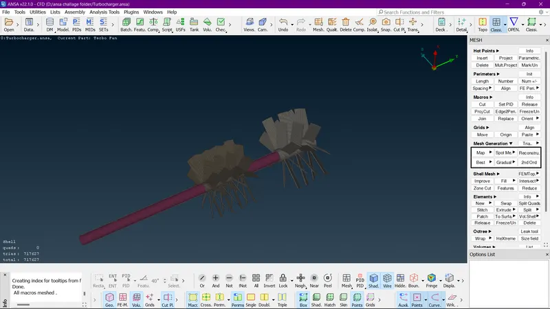
133. Like this we will assign all the PIDs name and PID color.
134. All the PIDs name given and geometry assigned.
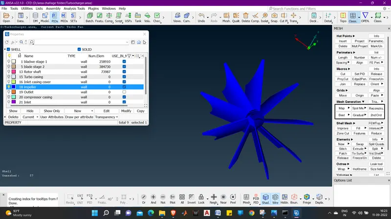
135. Now we will go for a last geometry check and we have no intersection error left.
136. We will now assign meshing target lengths to the PIDS.
136. Fisrt we wilL assign to PIDs which are to be assigned as 1mm target lengthfor 1mm
137. For assigning the PID target lenght, we have to select the PID in Properties.
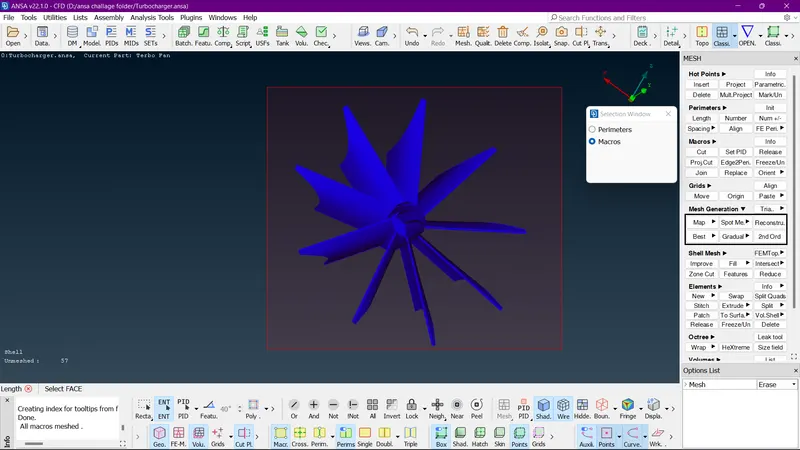
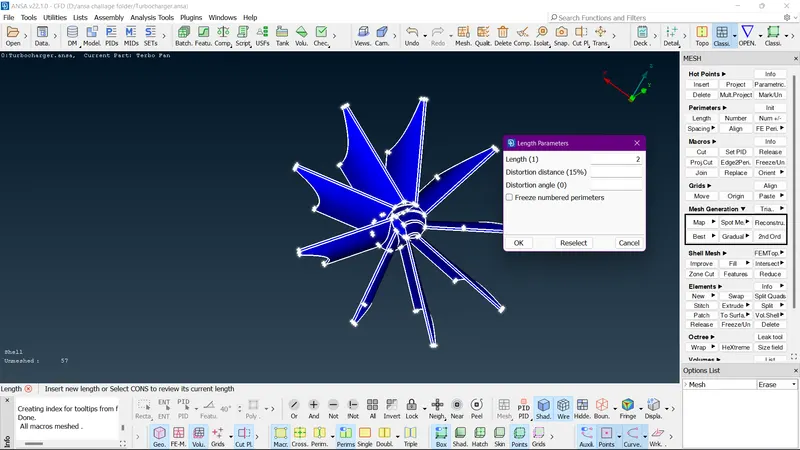
138. Now we will hide all the other components by switch off the bulb sign.
139. Now we will close the properties window and go to mesh mode .
140. Now we will set the target length for the blades stage 1&2 and shaft rotor by unhideing all other PIDs.
141. Now we will go for assigning the target length.
142. We will select length option, do the whole selection for perimeters and give the target length as 1 mm .
143. Now click ok and exit the perimeters assigning.
144. Now we will assign target length for macros as 1 mm.
145. Now click on ok to exit with macros command.
146. Now we will go for setting up the mesh perimeters for the PIDs, we will only set the minimum and maximum length from 0.5 mm to 1.5 mm.
147. Now click ok and our mesh perimeters are set.
148. Now we will go for quality criteria for theese PIDs.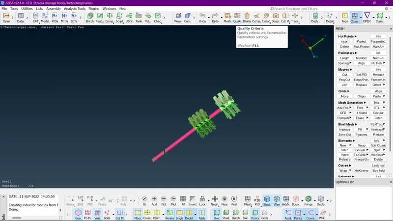
149. Now click on apply and click ok.
150. Now we will go for meshing the selected PIDs.
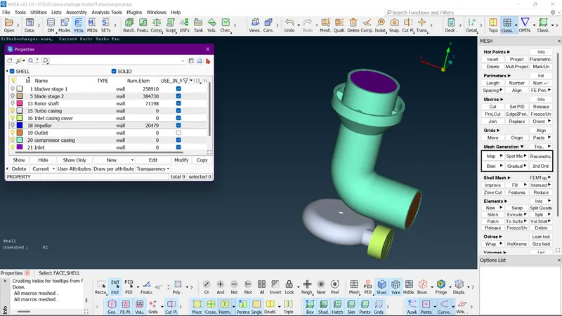
151. We will go for SPOT MESH ( VISSIBLE ).
152. When we click on visible the mesh is generated.
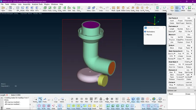
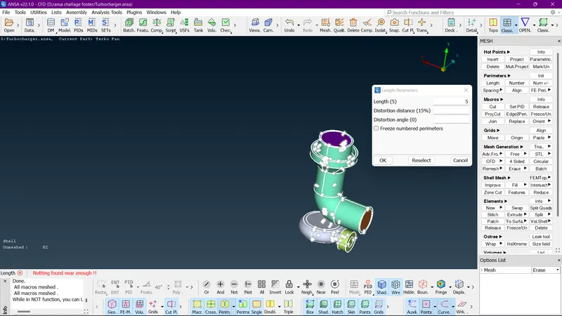
153. The mesh is generated.
154. Now we will assign target length for the impeller with 2 mm mesh.
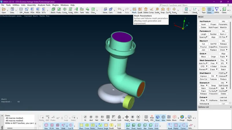
156. For that will hide the existing vissible PIDs on screen and unhide Impeller PID.
157. We will now close the properties window and go gfor assigning the target length by LENGTH in PERIMETERS TOOL BOX.
158. We will first do box selection for parameters, middle click and set target legth to 2 mm.
159. Click ok, do box selection for micros and give the target length as 2 mm.
160. Now we will set the mesh parameters for the vissible geometry on screen .
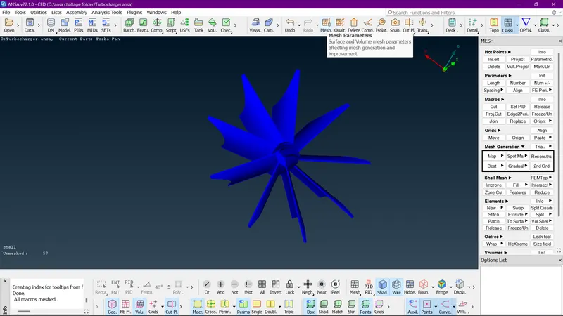
161. We will set minimum and maximum target lenth from 1mm - 3mm .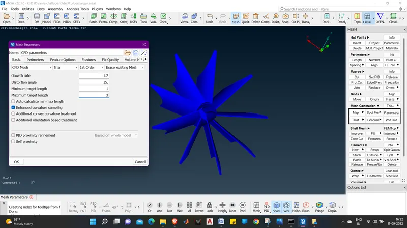
162. click on ok and go for assigning the quality criteria to the vissible geometry on the screen.
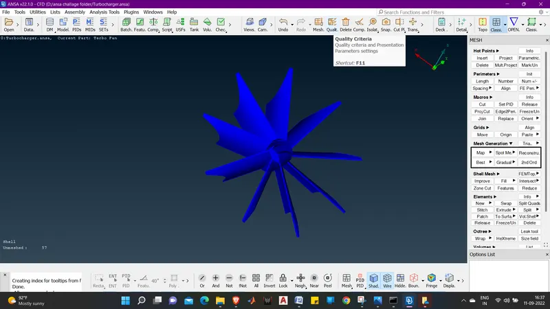
163. Select minimum and maximum legth from 1mm - 2mm .
167. Click on apply then ok.
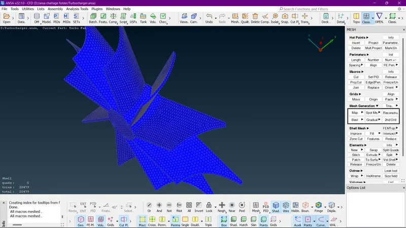
168. As we have assigned the quality criteria we will again go for SPOT MESH (VISIBLE) and click ok..
169. We can see that the mesh is done properly.
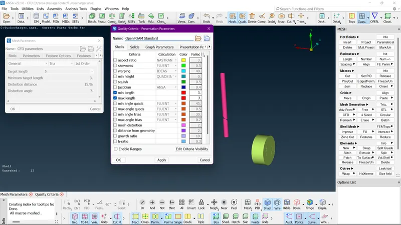
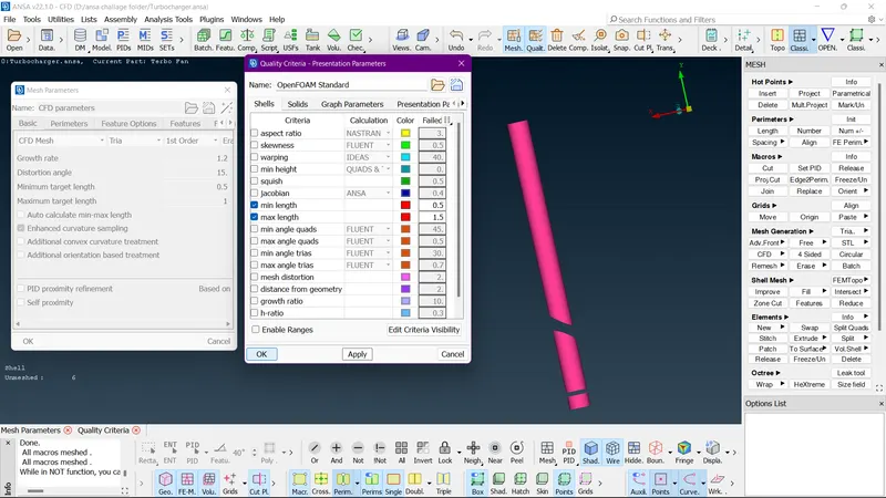
170. Now we now go for assigning target length to PIDs with 5mm target length.
171. We will hide the existing PID on screen and unhide te PIDs , which eill be given target length 5 mm.
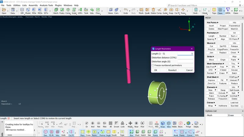
172. Now we will assign the target length to the vissible geometry using LENGHT in PERIMETERS.
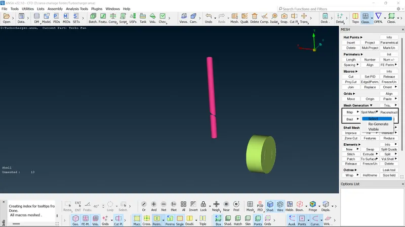
173. We will first do box selection for perimeters, middle click and set target length to 5 mm.
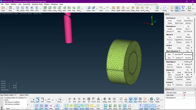
174. We will do box selection for macros, middle click and set target length to 5 mm.

175. we will assign the mesh parameters for the vissible geometry on screen .
176. Go for general mesh and select minimum and maximum target length from 3mm - 7mm, click on ok.
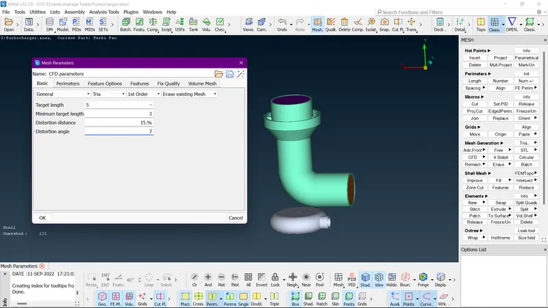
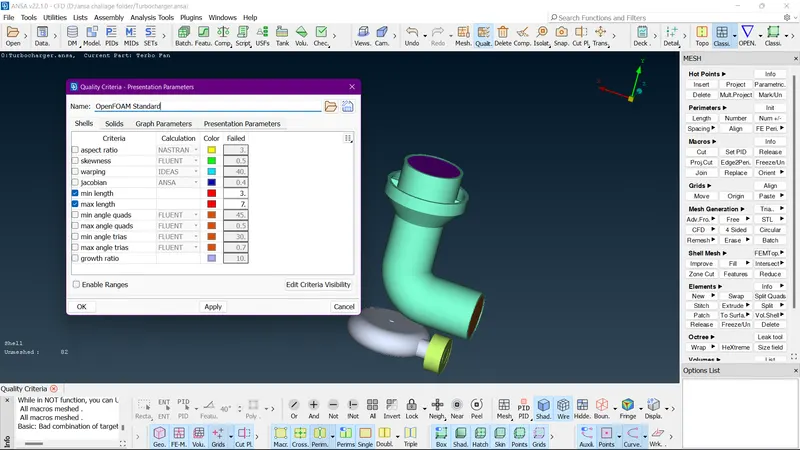
177. We will now go for assigning the quality criteria for vissible geometry on screen.
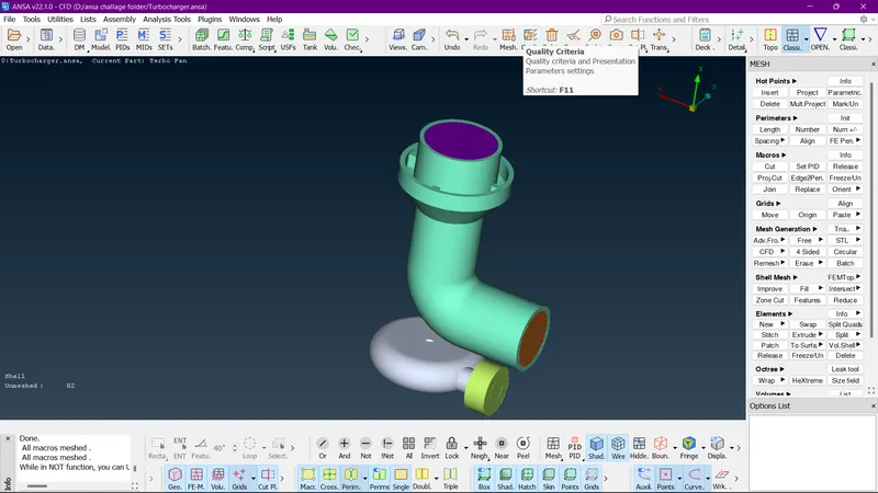
178. Select minimum and maximum target length from 3mm - 7mm, click on apply then ok.
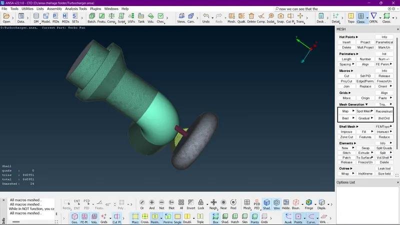
179. As we have assigned the quality criteria we will again go for SPOT MESH (VISIBLE) and click ok.
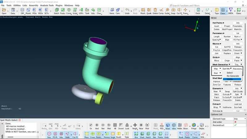
180. We can see that the mesh is done properly.
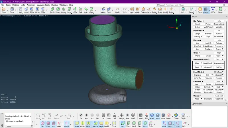
181. now we will do all and see the meshing for all components is done or not.
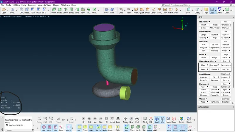
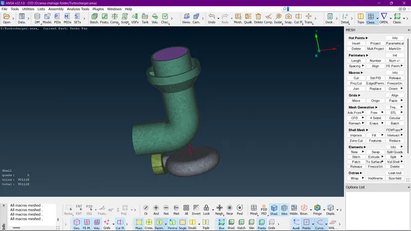
182. We can see on the left bottom corner that its showing 13 unmeshed geometry.
183. So lets check which all geometries remained unmeshed by right click on unmeshed and selecting show only.
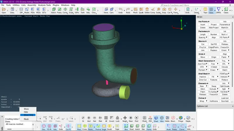
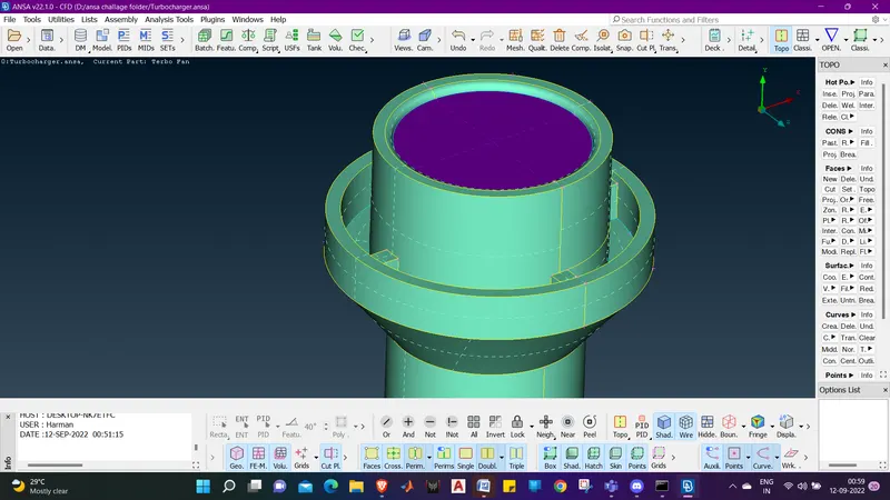
184. we can see the parts of the shaft rotor and inlet casing cover are remaining unmeshed.
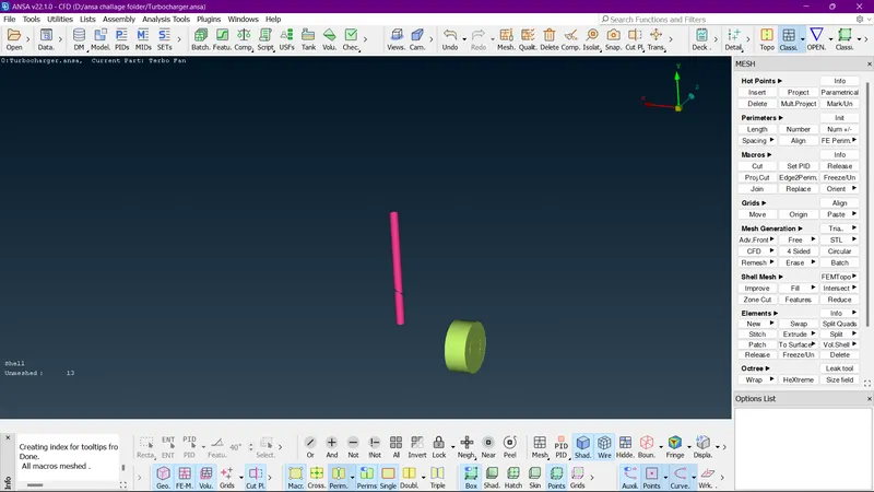
185. we can see that there are 13 elements which are unmeshed.
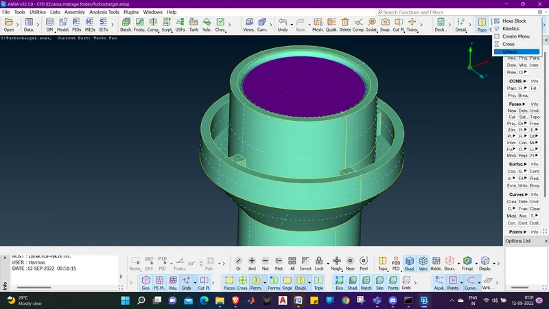
186. as we know the previous meash we done was 5 mm mesh and all the quality criterial and mesh parameters are according to 5 mm.
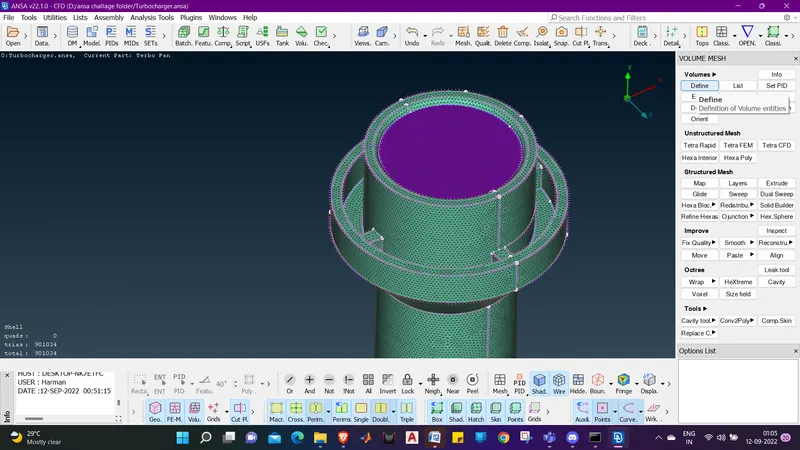
187. so we will first check both the mesh parameters and quality criteria again.
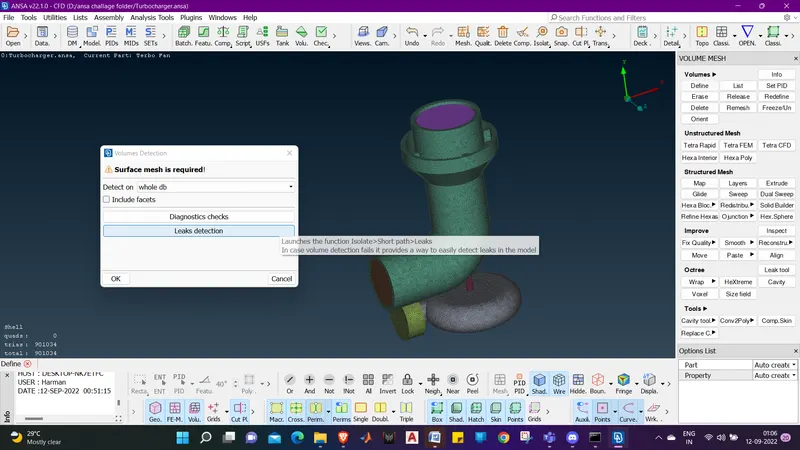
188. Now we can see that the quality criteria are same and we can proceed for mesh of inlet casing cover.
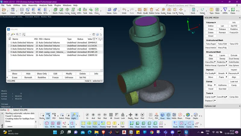
189. Now will select SPOT MESH (SELECT) .
190. selected the INLET CASING COVER and we got it meshed properly.
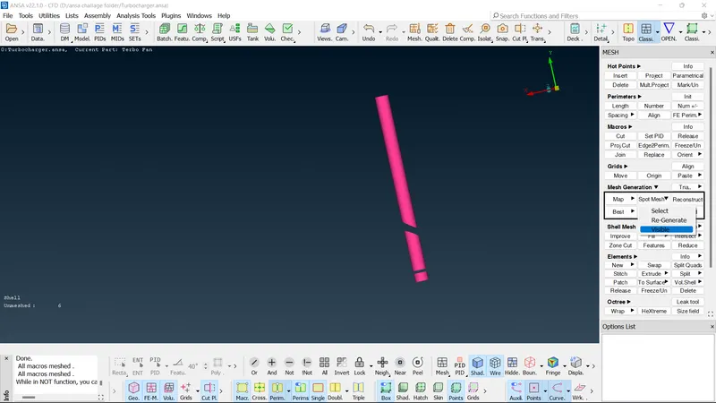
191. Now we will do the same for the shaft rotor by checing all the quality criteria , meah parameters and length parimeters.
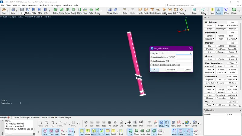
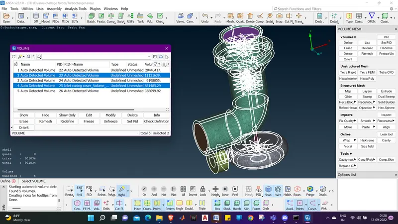
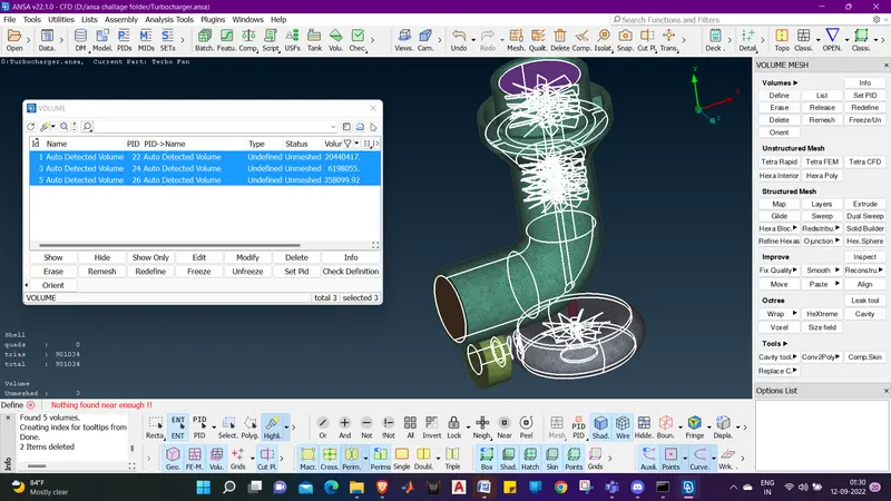
192. Now we will go for SPOT MESH ( VISIBLE ).
193. Now we can see that the unmeshed part are meshed now.
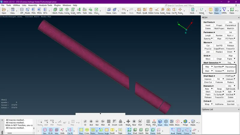
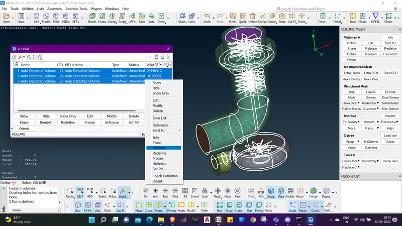
194. lets click ALL and check again if there is any unmeshed element left.
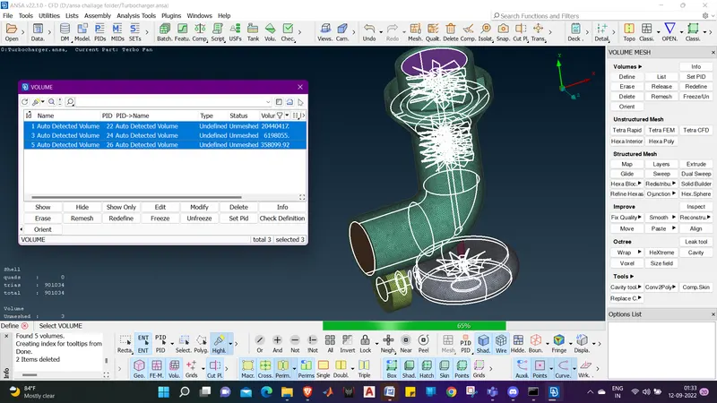
195. Now we can see that there are more unmeshed surfaces as compared before.
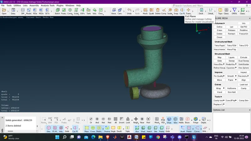
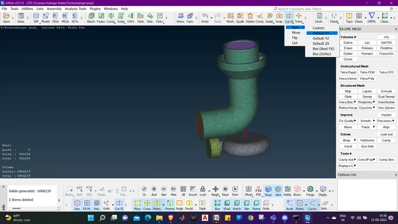
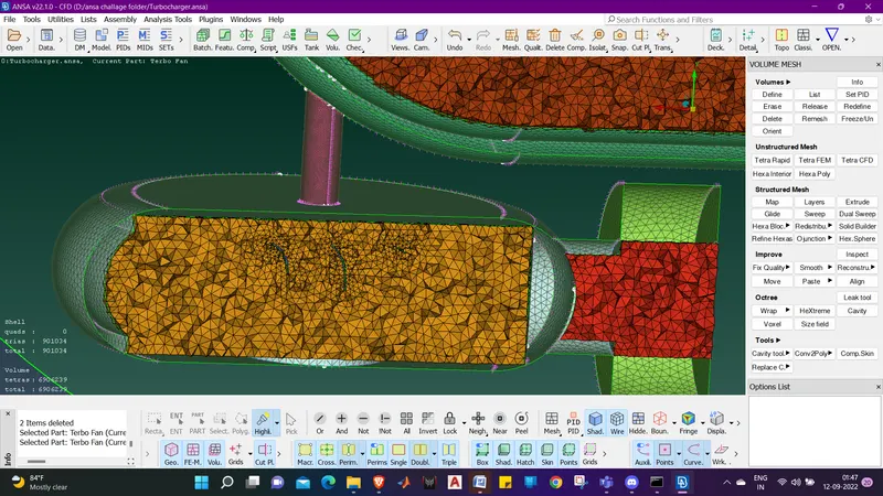
196. The reason behind this is that we did the mesh in vissible mode by hiding the component and also due to mismatch of mesh lengths.
197. we will again have to do the same process to get the disired mesh and no unmeshed component left.
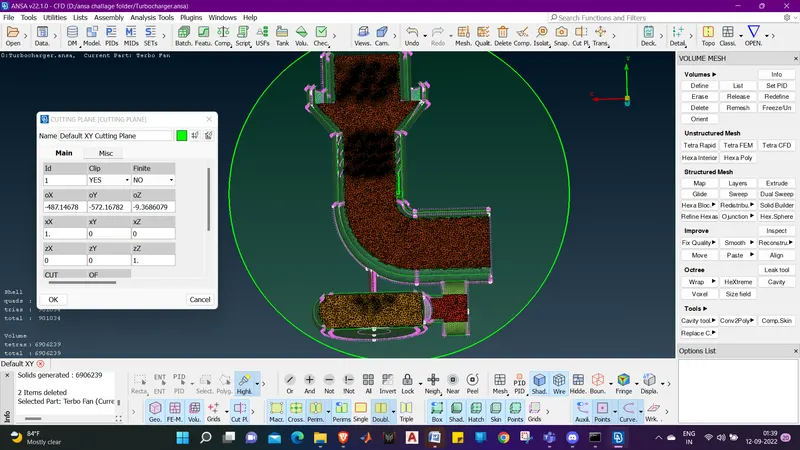
198. After doing all the mesh parameters and qulaity criteria and meshing we have the final mesh which is fine now.
199. we can see that the mesh is generated with no unmeshed quantity.
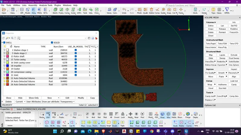
200. There was a mistake in the model geometry cleanp that we created the wrong surface with a wrong coon . if we don't correct this it will make a lot of problem in volume mesh.
201. Now we will go for volume meshing.
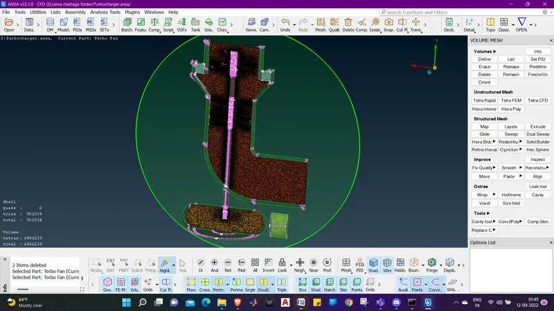
202. For volume meshing we will first select vol. mesh from the drop down window in mesh tol bar.
203. Now we will go for DEFINE .
204. When we click define the pop up window of volume detection will open in which we have to select WHOLE DB and click ok.
205. now another pop up box will open which will contain Auto Detected Volumes.
206. now we willcheck one by one which volume to keep and which vlume to deete.
207. we will only keep internal volumes because it this is an internal flow geometry so we need internal volumes only.
208. we will keep keep 1st,3rd and 5th volume and other 2 we will delete.
209. We will now have 3 internal volumes.
210. now we will select all these volumes and right click to choose REMESH.
211. when we click on remesh the mesh process will start and take few time to process.
212. We will get the volumes meshed and to see the mesh produce we will use universal cut plane command.
213. we will make new cut plane xy plane.
214. we will now select the point where we want the section view for mesh.
215. when we section the model we can see the internal volume mesh created,
216. we have to hide surface mesh so that we can have aproper view of volume mesh.
217. we can see the internal volume without section.
218. we can see the volume mesh properly. we can make one more section and hiding the first one.
219. now we will have a close look on the section 1.
220. now we are done with the volume meshing , the challenge is completed and we will save the file.
Rersults. :-
follow the link for the Ansa challange 3 file with volume meshing done.
Conclusion :-
https://drive.google.com/file/d/1FQLUU4SPnBB30GmcQoxCf1gAWTzEr4kE/view?usp=sharing