Project 1 : CFD Meshing for Tesla Cyber Truck
Aim:-
For the given model, check and solve all geometrical errors and Assign appropriate PIDs. Perform meshing with the suitable Target length and element Quality criteria.
Target lengths for the different parts of a model can be decided by your own. Finer mesh will give good results and will compromise with the longer processing time.
Procedure:-
- Open Ansa
- Open your file from the downloades location.
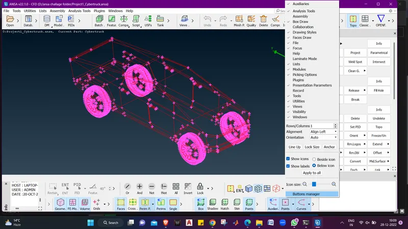
- Once the file opens right click on the tool bar menu at bottom and check the box "Show Labels".
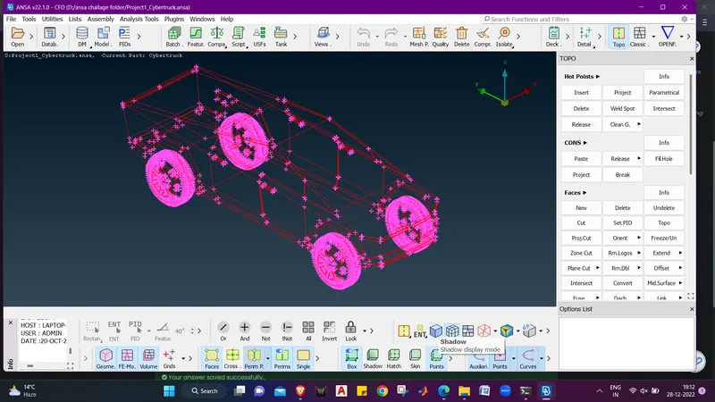
- Now we can se that the model is in wirefame mode we will switch in shadow mode by clicking on the shadow tool.
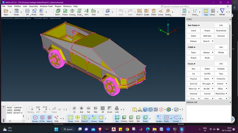
- Now we can see the model in solid form.
- Now we will first do the geometry check :- checks - checks manager - Click on execute - we get the grometry and intersection errors.
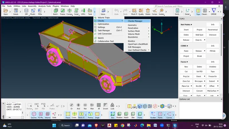
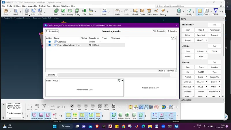
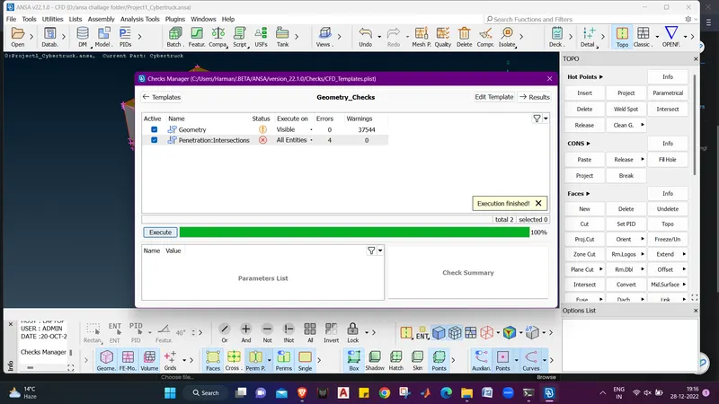
- Double click on the geometry it will open a dialogue box which shows geometry errors (37544 errors).
- Mostly errors are single cons, lets try to rectify them.
- we will first go for TOPO cleanup.
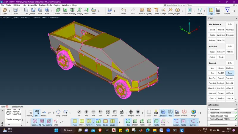
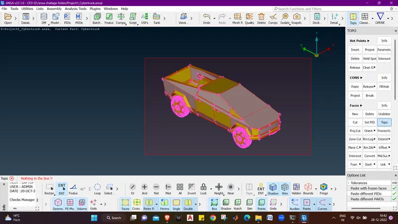
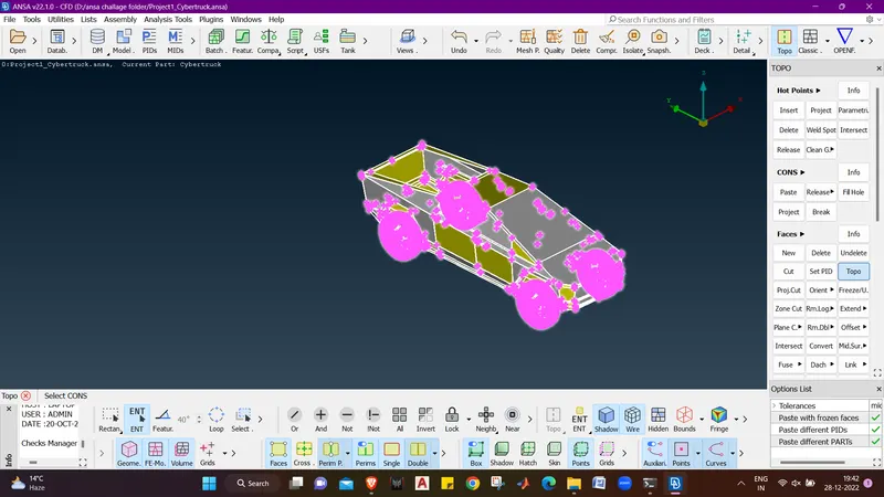
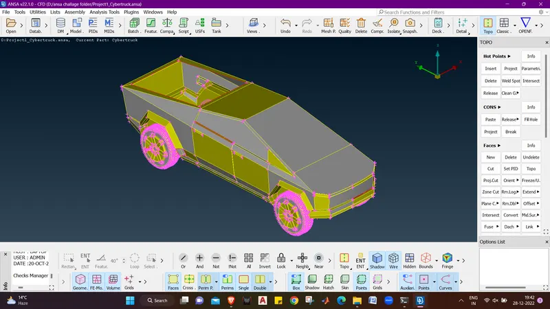
- Now we can see that many of the red cons vanished due to topo.
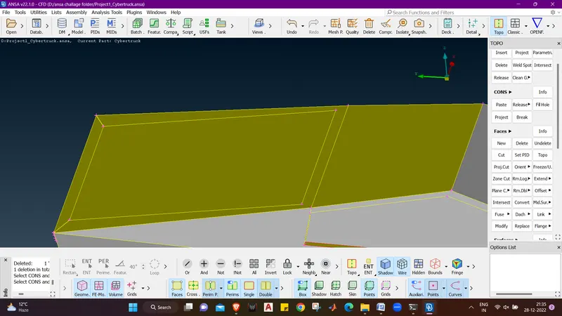
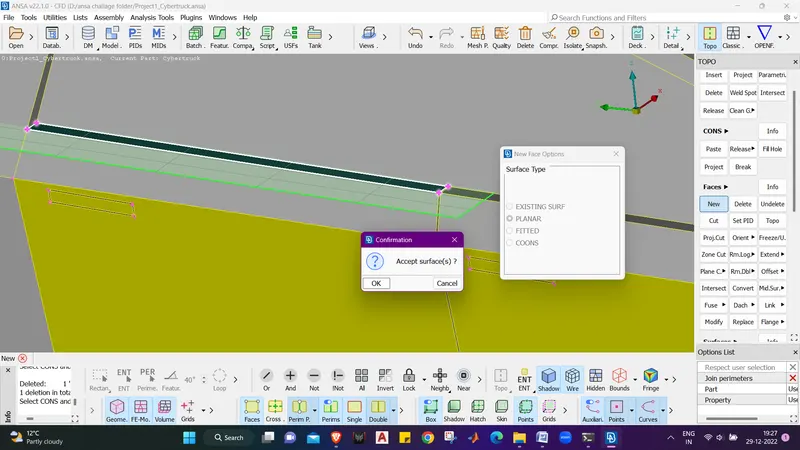
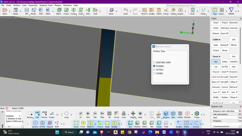
- Lets create a face here using NEW option in Faces menu. NEW - Planar - Loops - Middle Click.
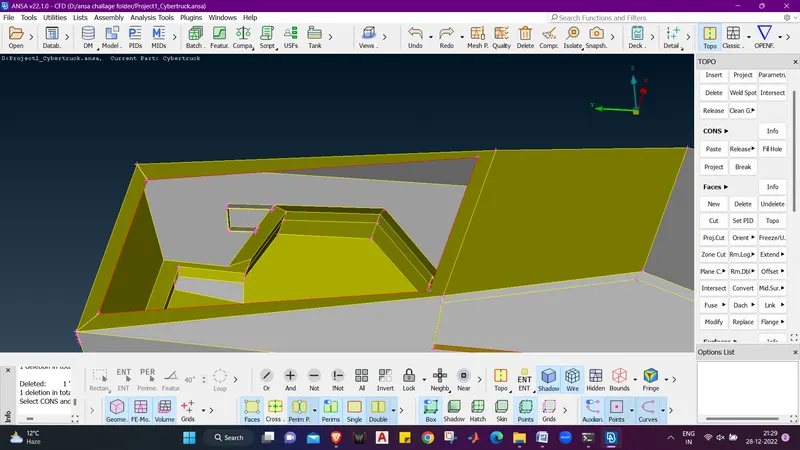
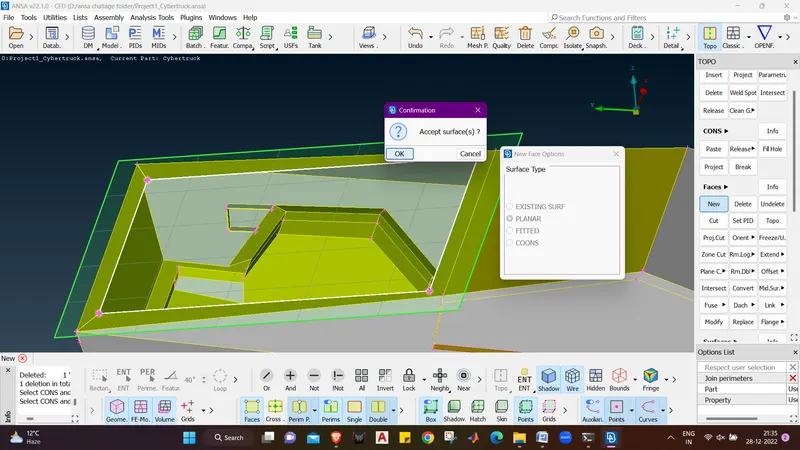
- Now lets see whether there is any internal body intersections which may cause errors in dividing the body ar may cause skewed elements in the model when meshed.
- We will hide the bootom surfaces to check the geometry from internal using NOT.
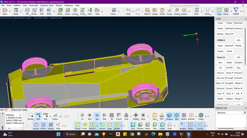
- We can see that in the front side there are surfaces inside.
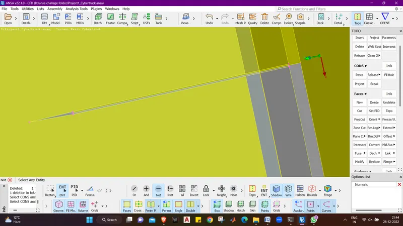
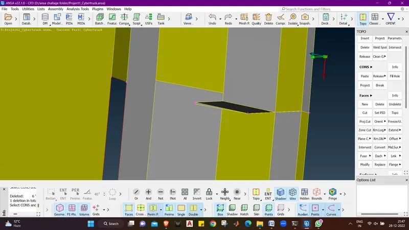
- we must delete these faces and create new faces.
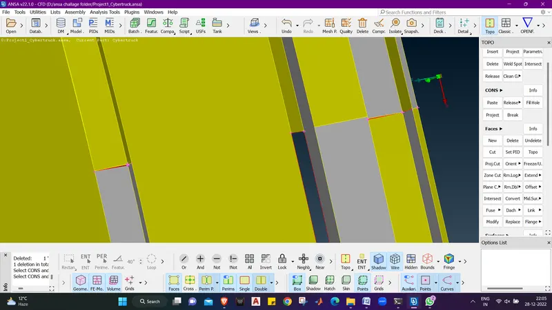
- After creating new faces we can now devide the geometry into 2 equal parts.
- we will use plane cut option to devide the model into 2 parts.
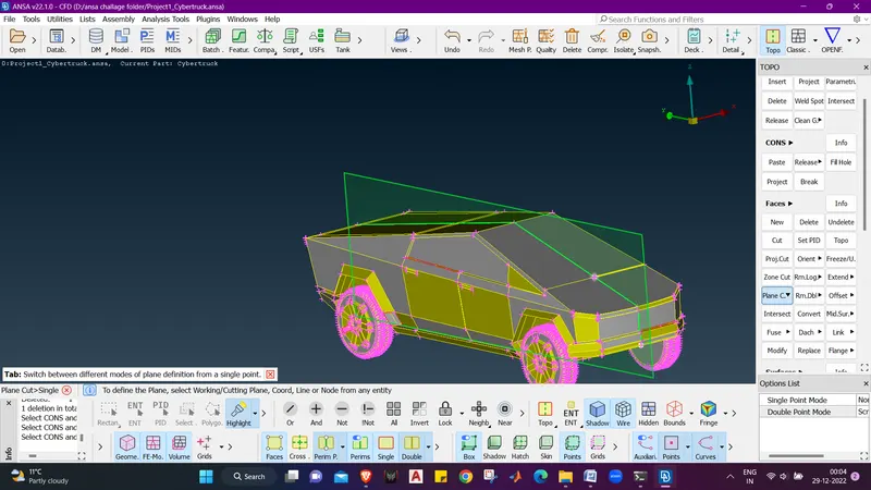
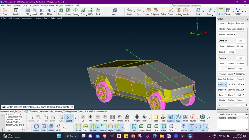
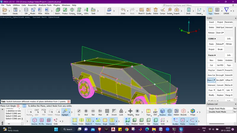
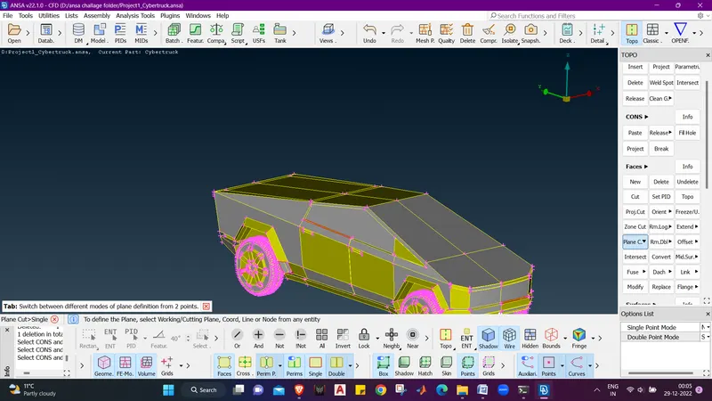
- we can see that the model is devided into 2 parts.
- we will now delete the other half using universal delete option.
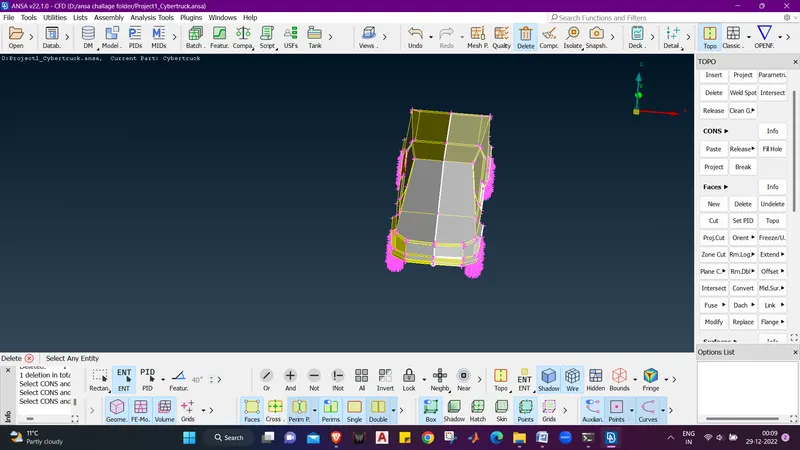
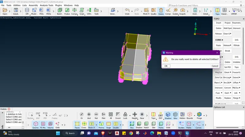
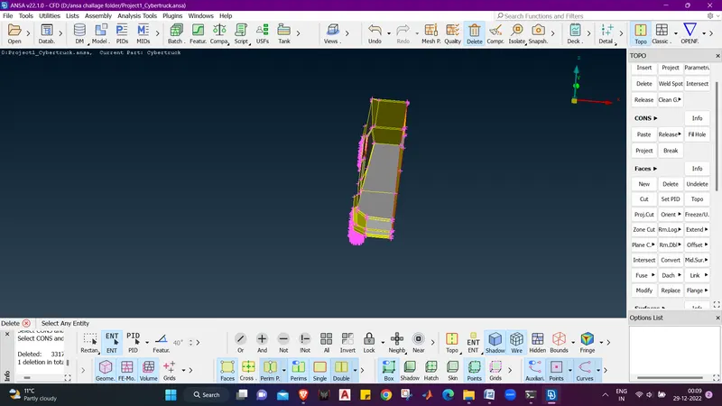
- we can see that the other half is deleted.
- now we will rectify the visual errors and resolve them
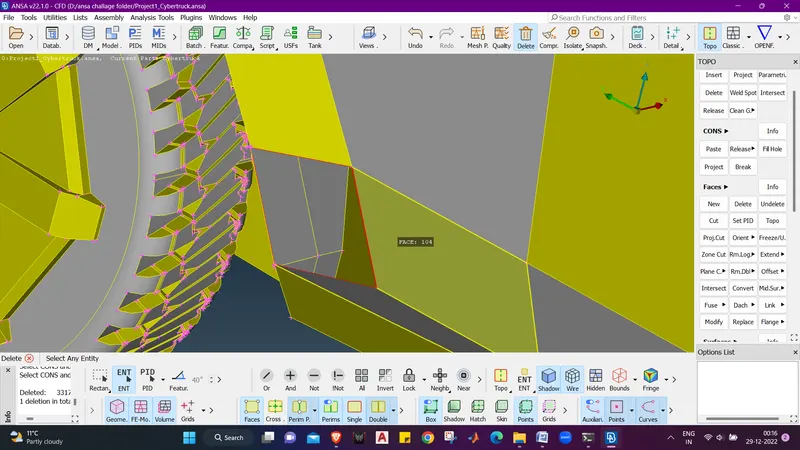
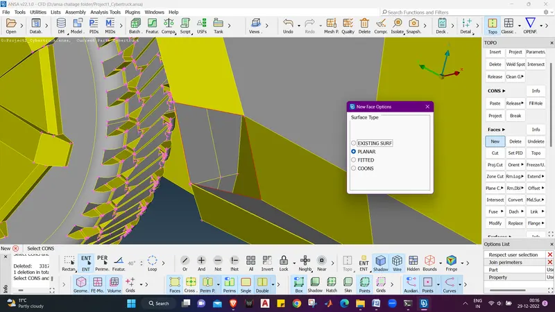
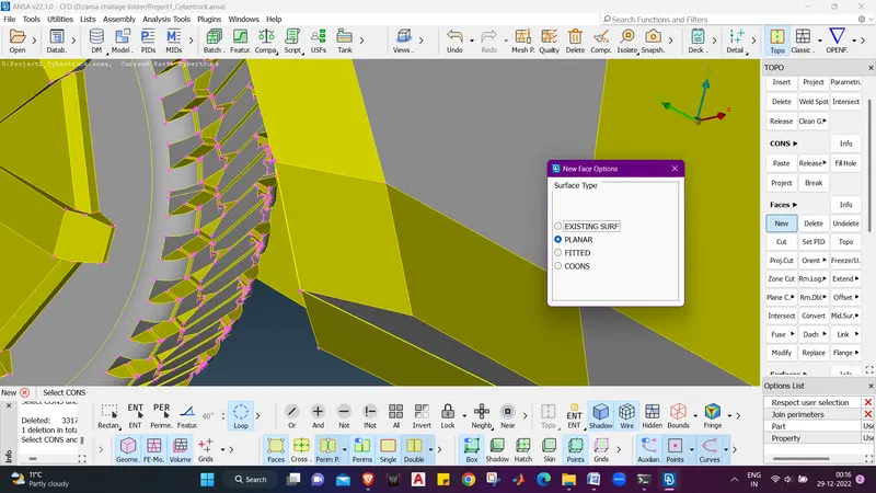
- We will rectify all the geometrical errors like this.
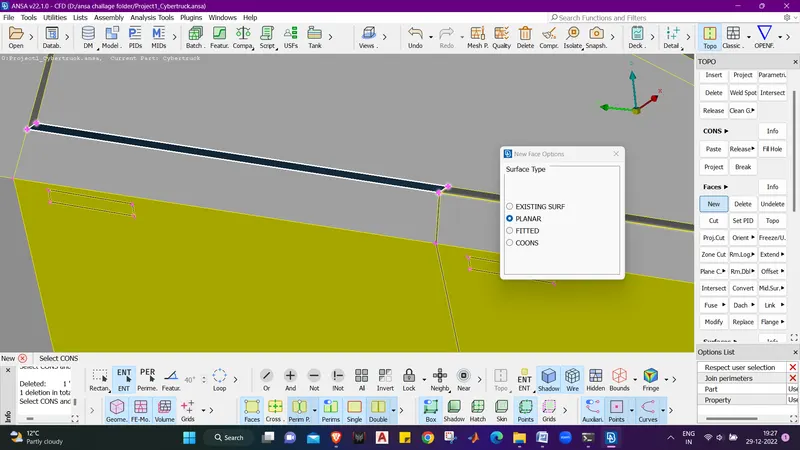
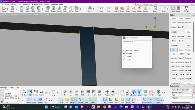
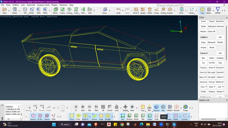
- we can see that there are no geometrical errors.
- now we will again o for the geometry check and check for the errors.
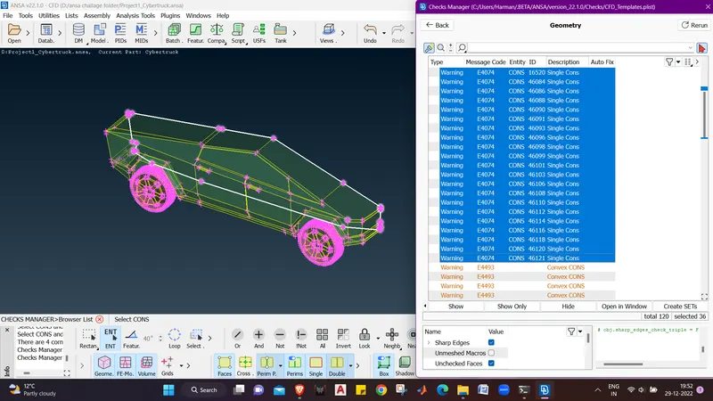
- we can see that the single cons are showing due to the the plane cut we did, that can be rectified when we mirror the whole geometry symetrically.
- lets see the peniteration errors now.
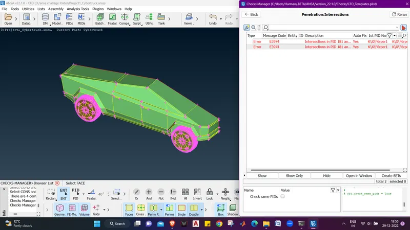
- we can see that we have 2 penitration errors. lets select the penitration errors and select show only.
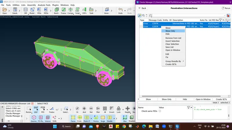
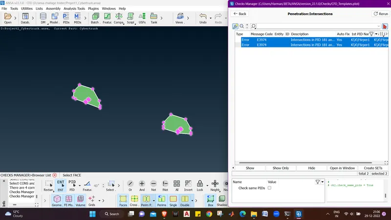
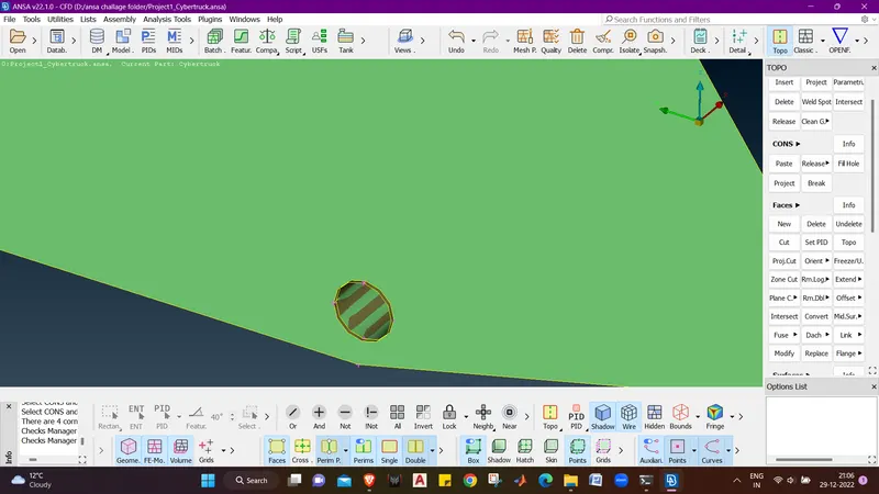
- we can see that there is a penitration btw the shaft of tyres and the mud flap.
- As the Mode is PID mode we can see that there is a overlaping surface which is making the penitration error. lets try delting this overlaping face to clear the penitration error.
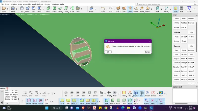
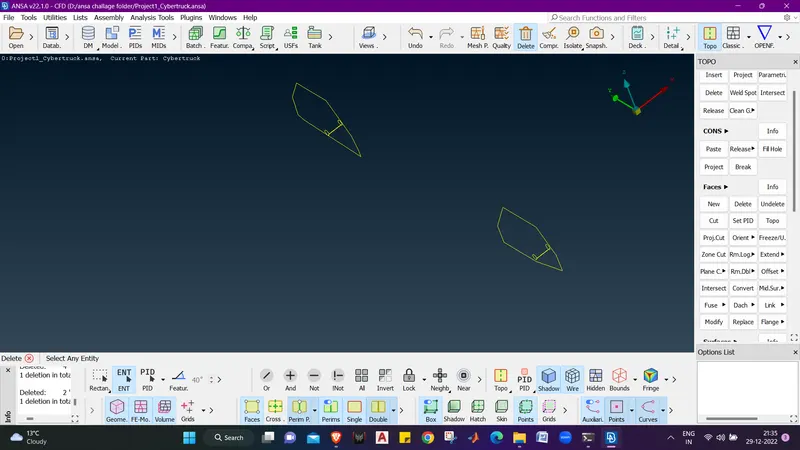
- Now we can see that there is no intersecion in the whell hump area.
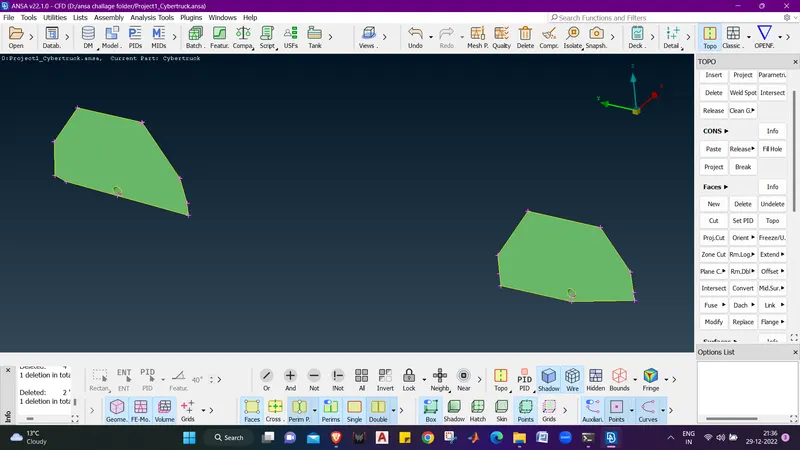
- Click on ALL to show the whole model.
- lets do a geometry check again.
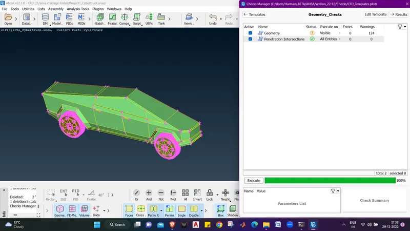
- Now we can see that there is no penitration errors.
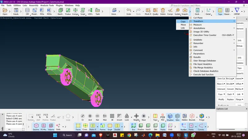
- Our next step is to mirror the model to crete the whole TESLA CYBER TRUCK.
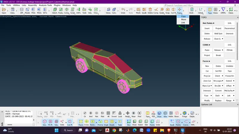
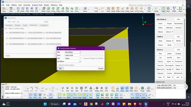
- we will use Universal transform to mirror the geometry. :- Transdorm - Copy - Entities seletion - symmetry - mirror 3 points plane - swlect points - apply - ok - finish.
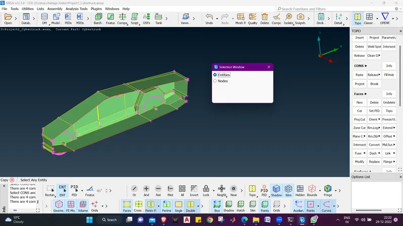
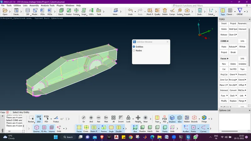
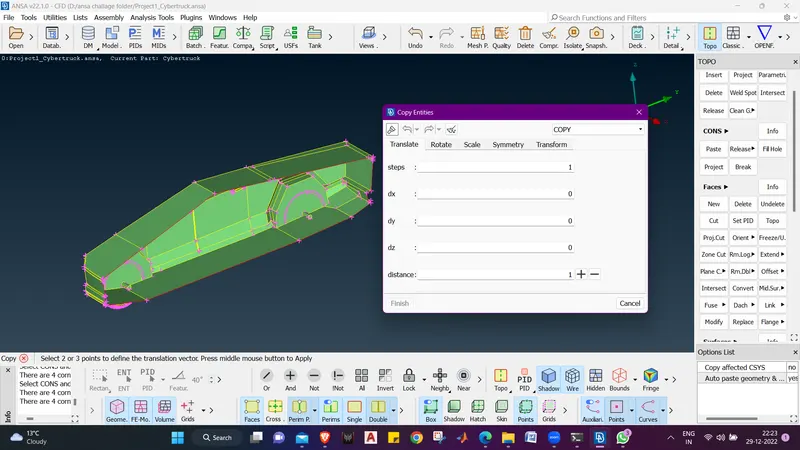
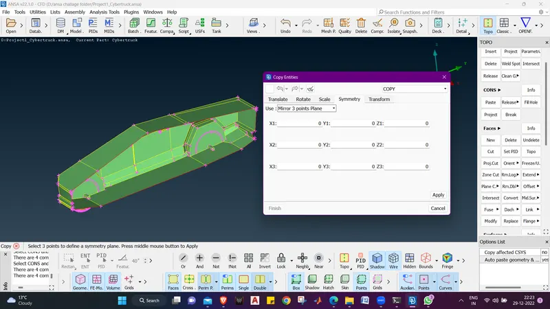
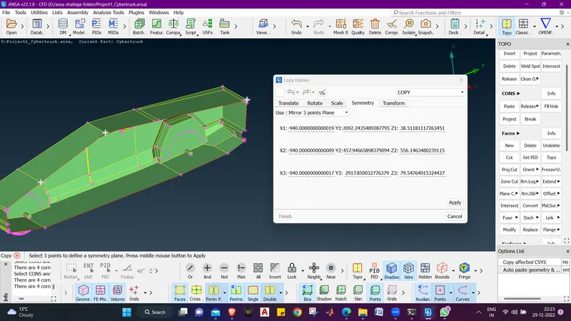
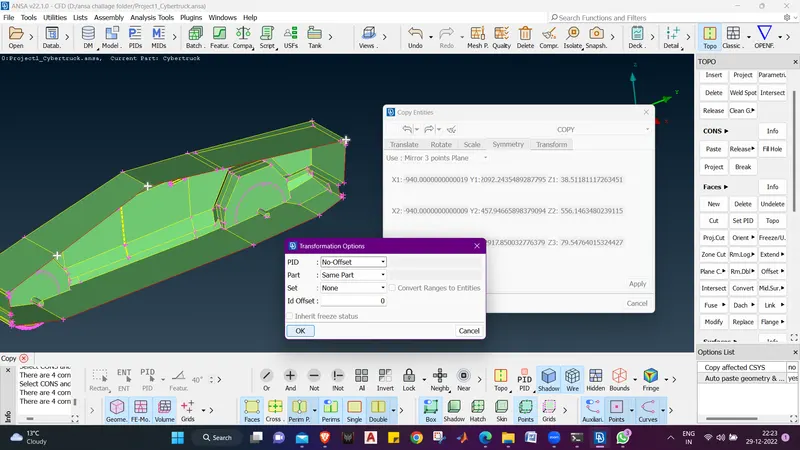
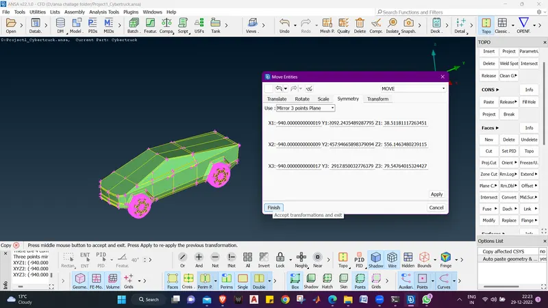
- we will now go for a geometry check .
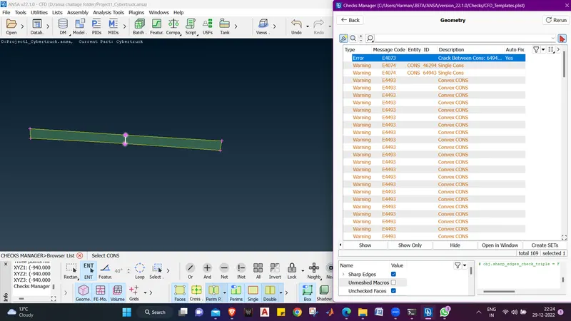
- we can see that there is a cracked coons we will hit a TOPO and we will try to clear the cracked cons.
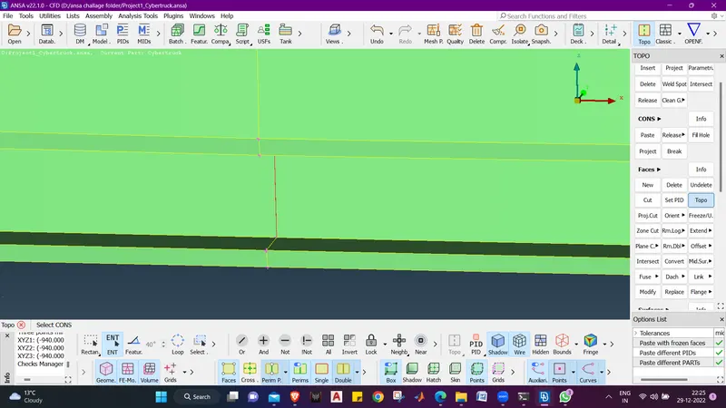
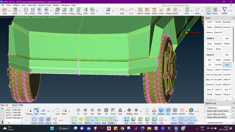
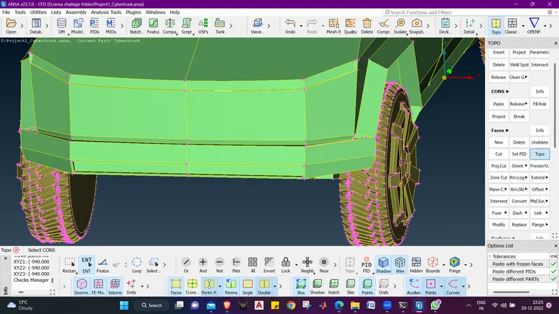
- As we can see that the cracked cons is relieved.
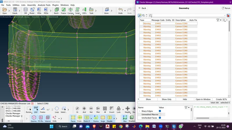 .
. - Now we have only left with convex cons. there is no need to rectify them. asthey won't create any problem while meshing.
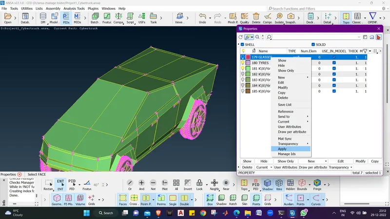
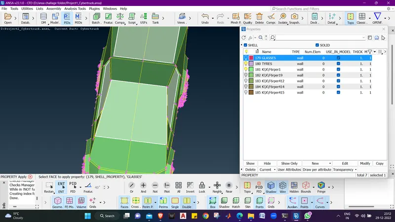
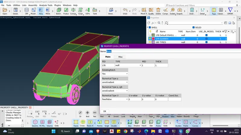
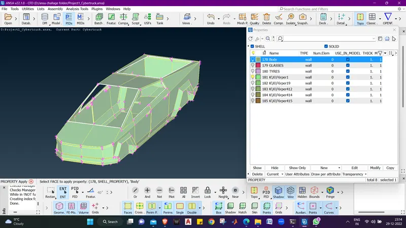
- Now we will Give diiferents PIDs to the differet parts and delete the other PIDs which are not required.
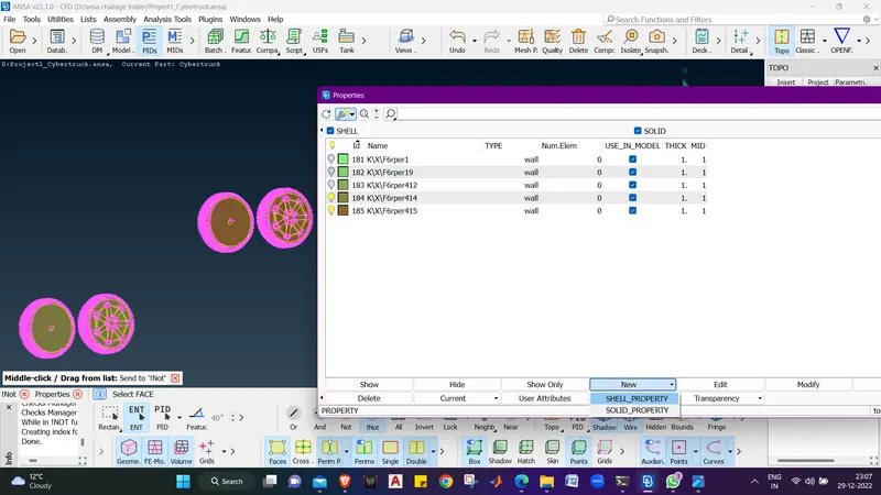
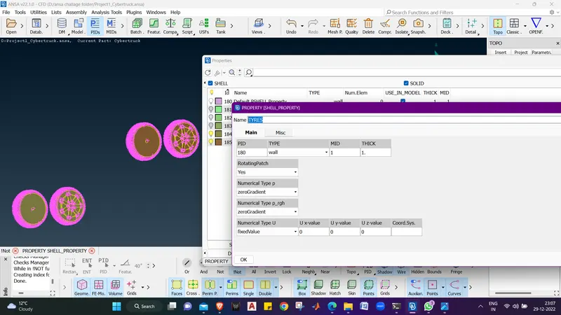
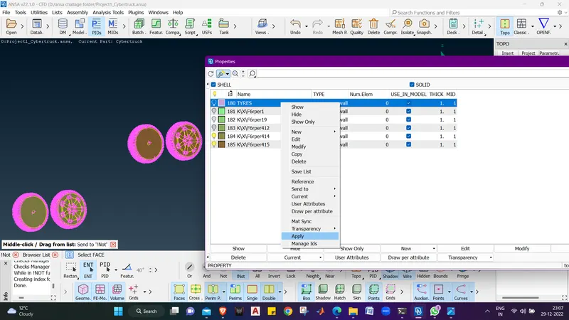
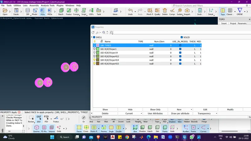
- Tyres are assigned and applied with a PID NAME :- TYRES.
- now we will create new PIDs
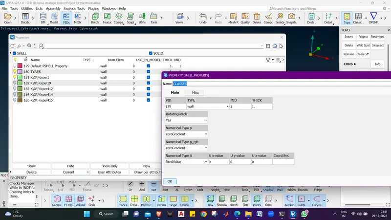
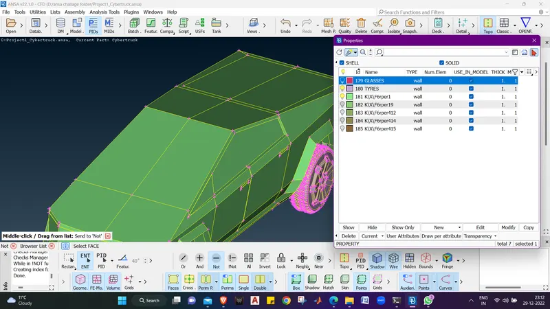
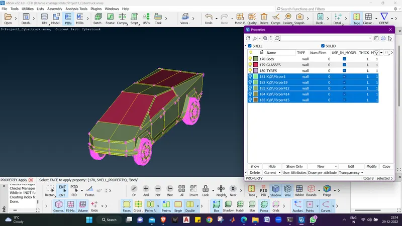
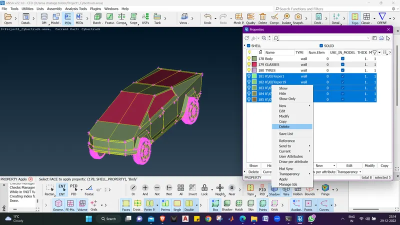
- Now we will switch from TOPO mode To CLASSIC MESH.
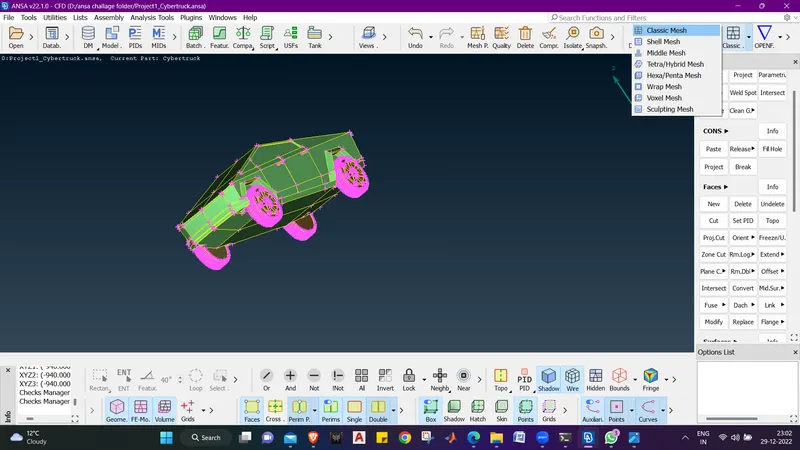
- here 1 thing i did that mirror the half part .
- i mirror the half part to check wheter here were any intersection.
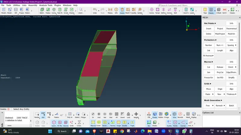
- meshing the whole body may take time so we will delete half of the body and then go for mesh.
- we will delete the half part using entity mode and box delection and middle click to execute the delete command.
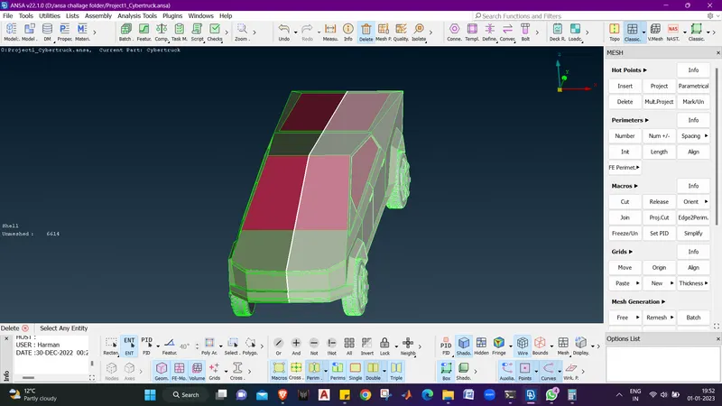
- We will give Body target length as 3 mm , Tyres as 2 mm & Windows as 2 mm
- Now lets isolate body for meshing.
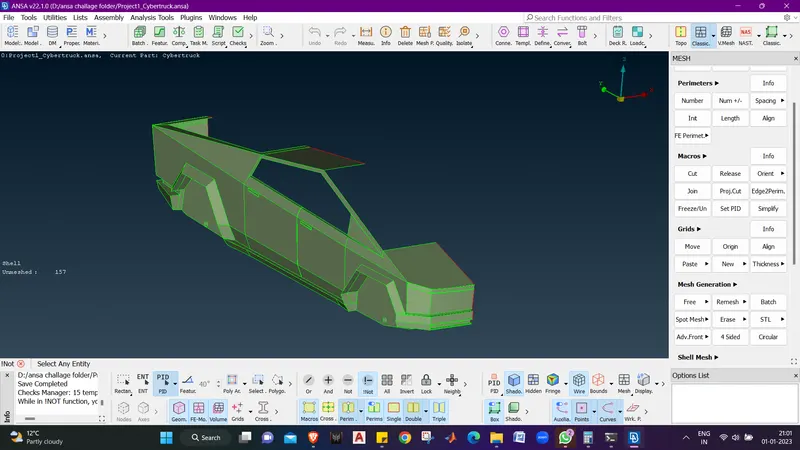
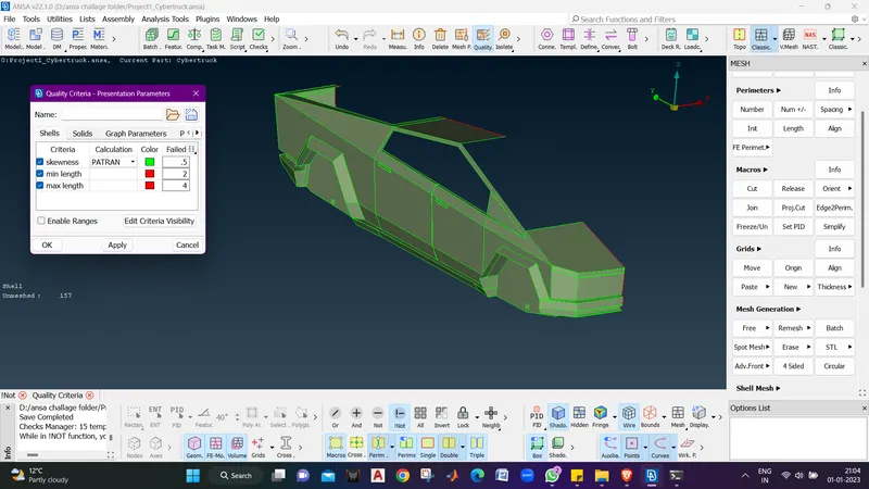
- We will first give quality criteria for body :- Min. length -2 & Max. length - 4 and skewness - 0.5.
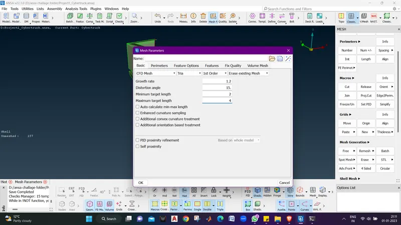
- Now we will give the mesh parameters :- select cfd mesh , tria elements, Min. length - 2 , maximum length - 4 and click ok.
- now we will select Length from Perimeters menu.
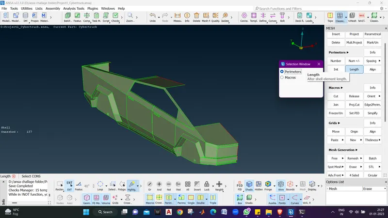
- Now we will give perimeters and macros length as 2 mm .
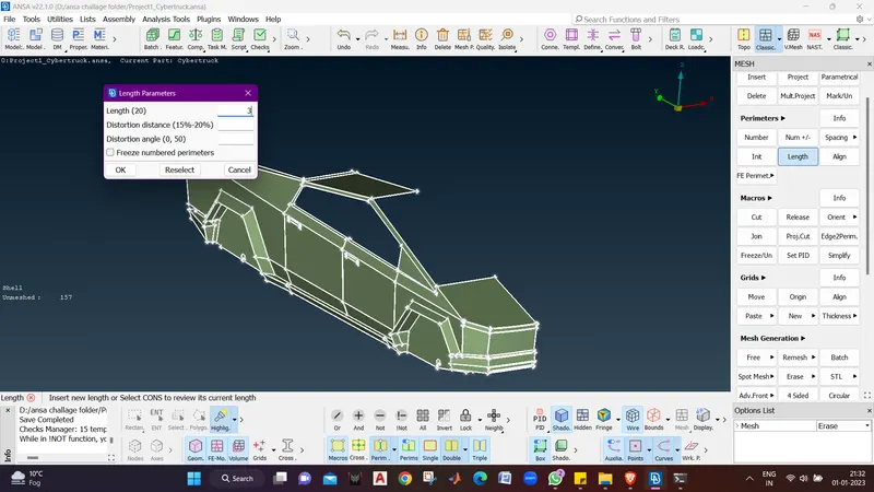
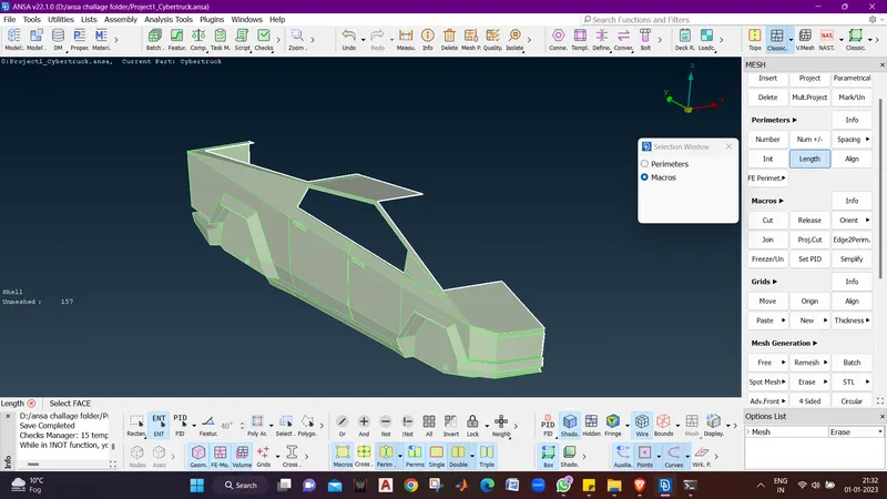
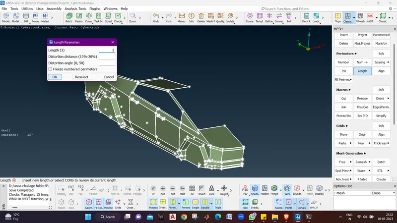
- Now we will go CFD mesh in Mesh Generation.
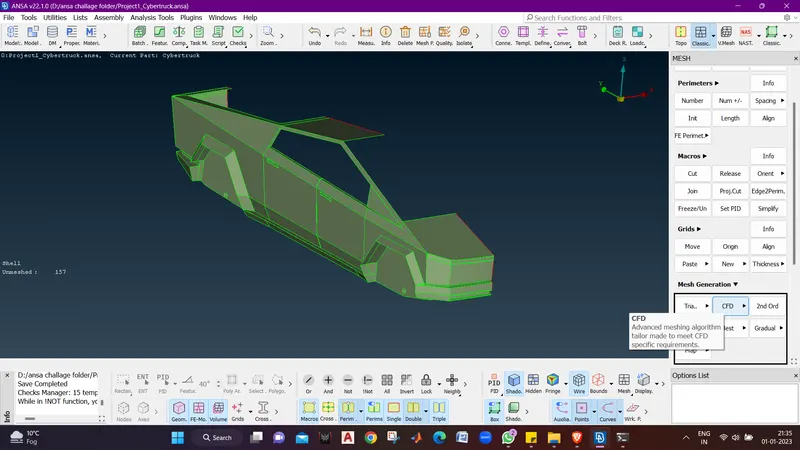
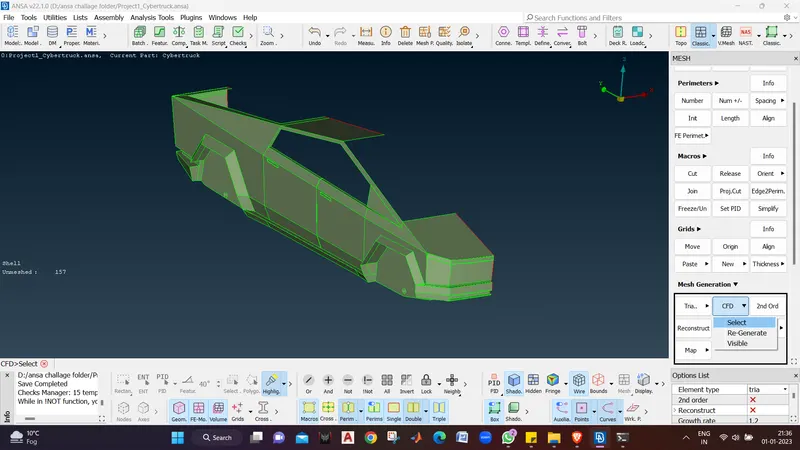
- Now select the body using PID mode and middle click to execute the command.
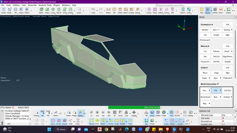
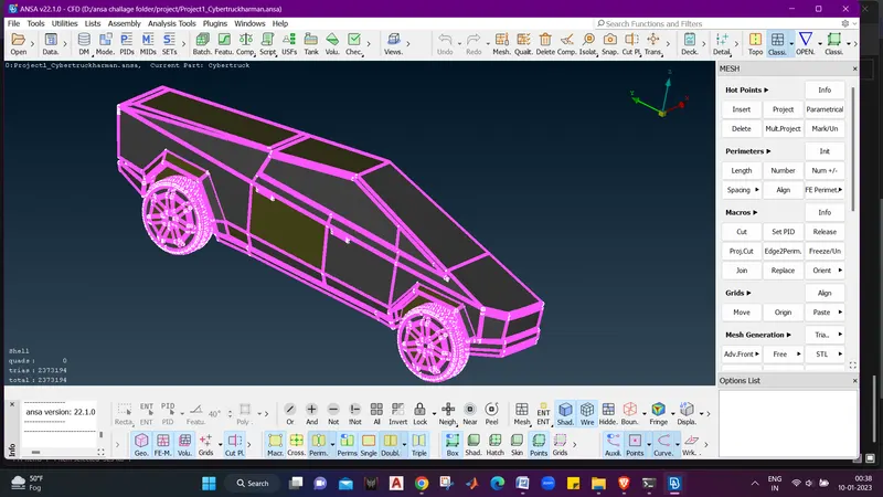
- we can see the mesh is completed without any mesh off elemets.
- Now we will use Universal TRANSFORM to mirror the whole model to create a closed body.
- We wil switch to TOPO mode now .
- Click on TRANSFORM - COPY - SELECT ENTITIES - SYMMETRY - MIRROR 3 POINTS PLANE.
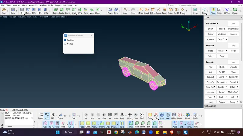
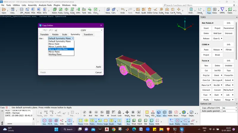
- Now we will select the 3 points.
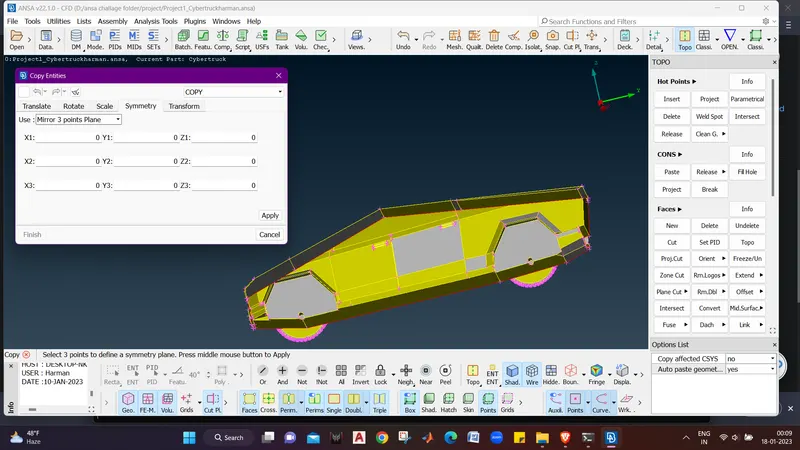
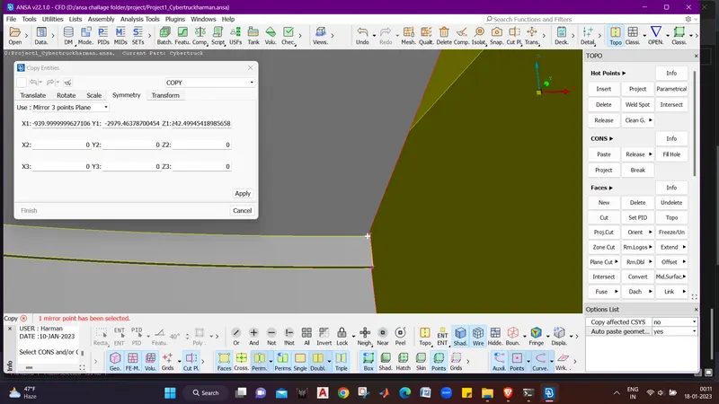
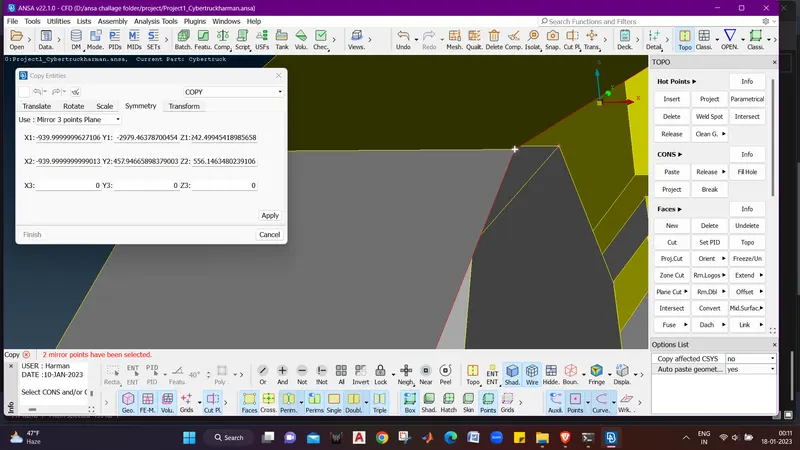
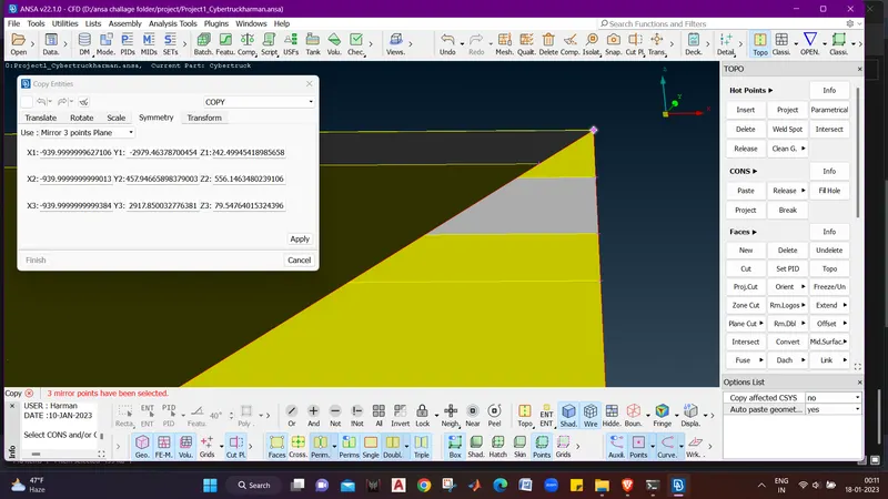
- And Now we will mirror the Body by clicking apply and then ok.
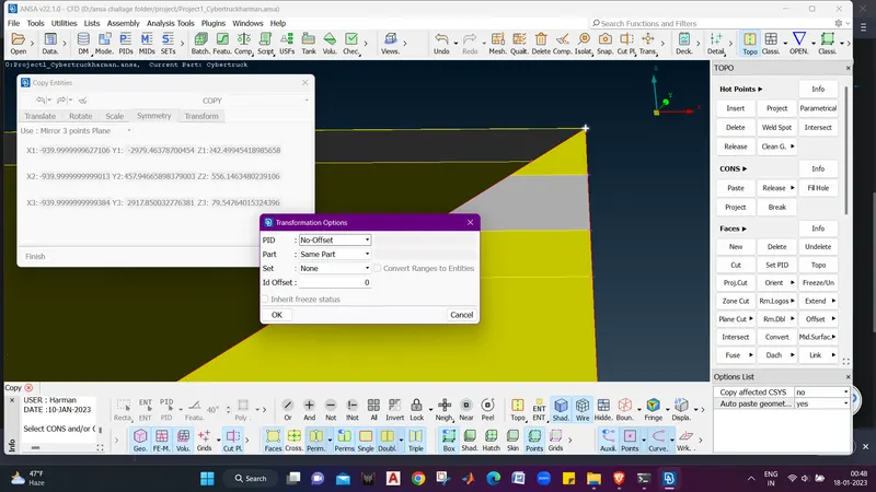
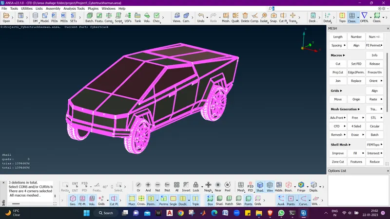
- now we can see that the mirror of the body is created Wth o elements left to mesh.
- now we will make a wind tunnel.
- Criteria for wind tunnel, considering length of truck as x
1. Front wall distance :- 4x
2. Back wall distance :- 6x
3. Side wall distance :- x
4. Top wall distance :- 3x
base distance should be more than the tyre distance from vehicle base or tyre shouldn't touch the base of wind tunnel. so safe distance to be taken as x/4.
- we will first measure the truck length. and truck length is 6000 mm.
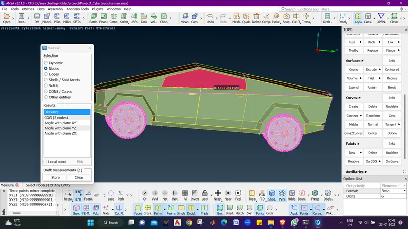
- Now we will make points from the car base center using relative points.
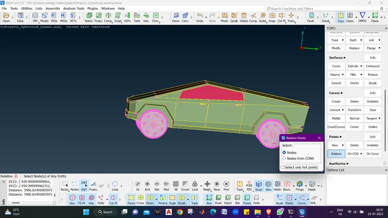
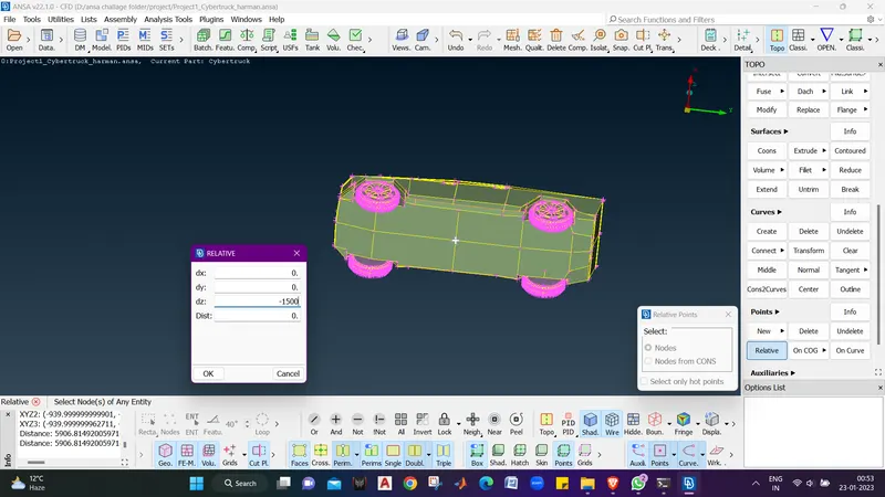
- The distance below the truck should be X/4 :- 1500 mm.
- Now middle click and click ok in the dialogue box and the relative point is created.
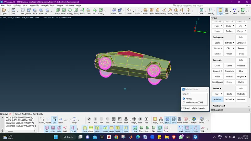
- Now we will create the front point which should be 4.5x towards front which is 27000 mm.
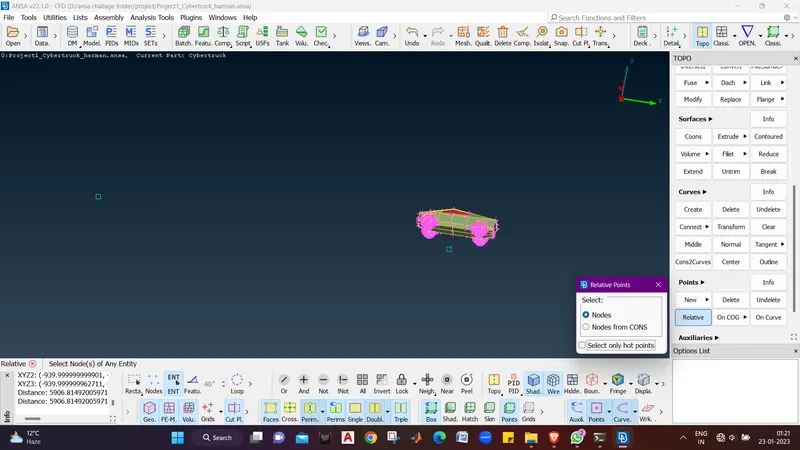
- Now we will create the rear point which should be 6.5x towards frear which is 27000 mm.
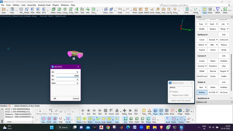
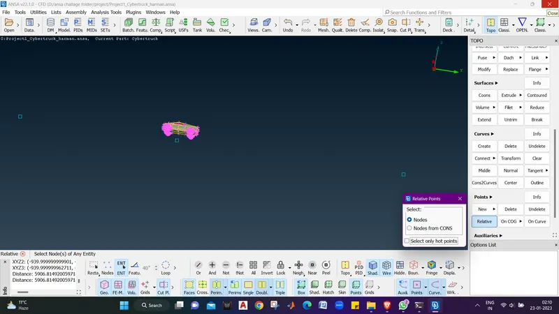
- Now we will check the width of the truck using measure tool.
- The width of the truck is 1795 mm.
- and we require X dimenesion for the wind tunnel on side.
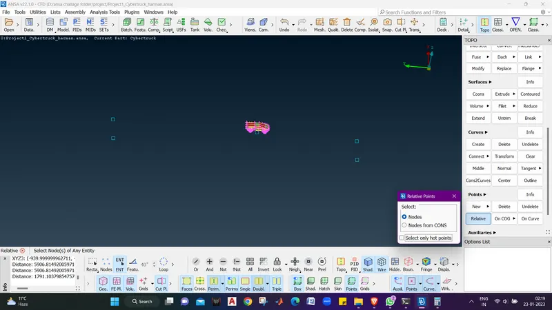
- We will add half of the with to X and make the 2 points copy using relative at the distance 6895mm .
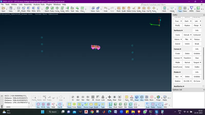
- Now we will copy these points to make the other side wall points at a distance 13795 mm .
- Now we will make a surface joining these points using CURVES - CREATE - LINES -SELECT 2 POINTS.
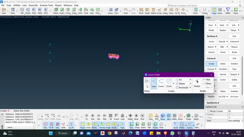
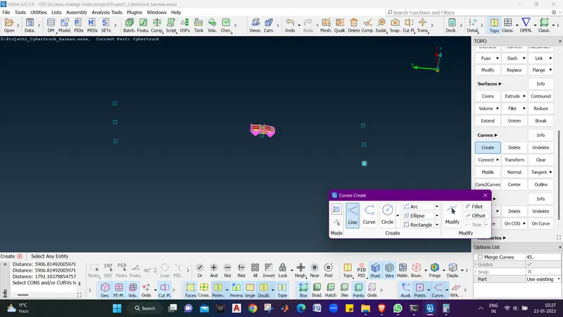
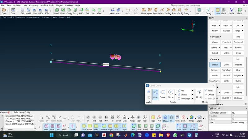
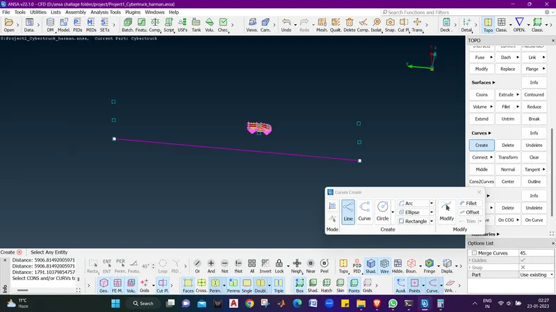
- Now we will join all the points like this .

- Now we will create a new face using FACES - NEW - COONS SELECT .
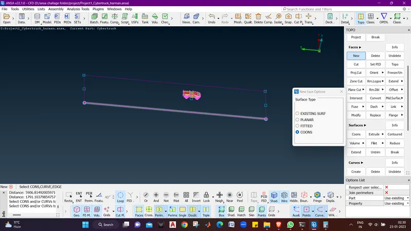
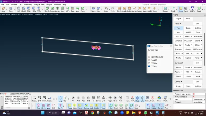
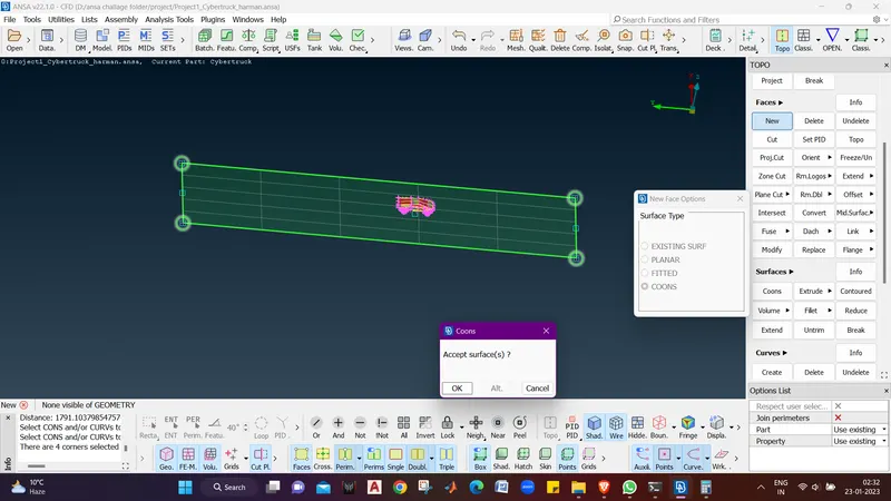
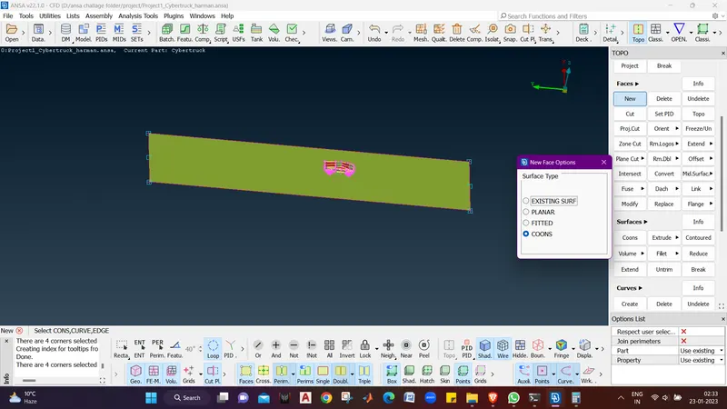
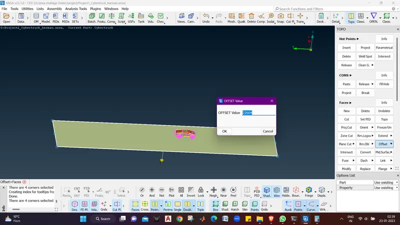
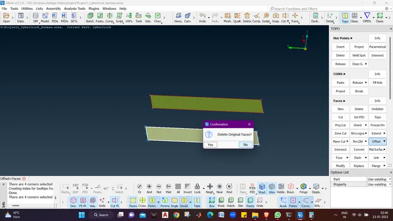
- Now we will check the vehicles height and add the floor and upper minimum height required to ooffset the surface. :- 3104 + 1500 + 18000 :- 22604 mm .
- Now we will offset the surface using Faces offset.
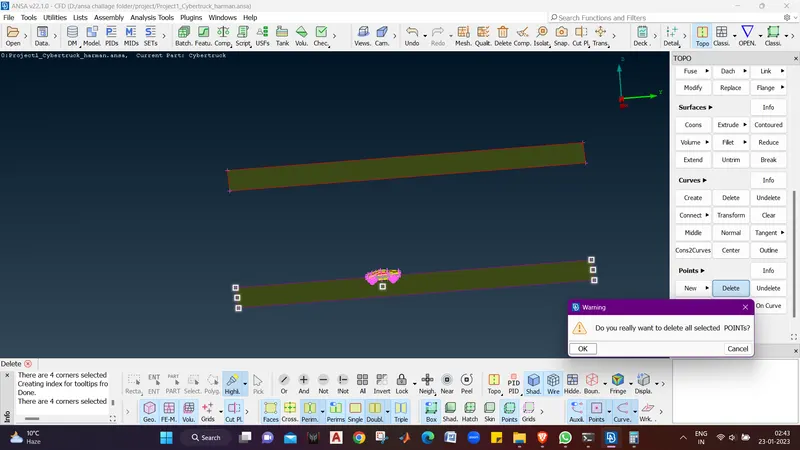
- Now we will delete all the points we created using Delete option in PONTS menu.
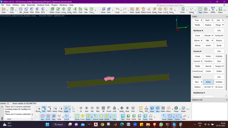
- Now we will create remaining walls of the wind tunnel usinf FACES - NEW - COONS .
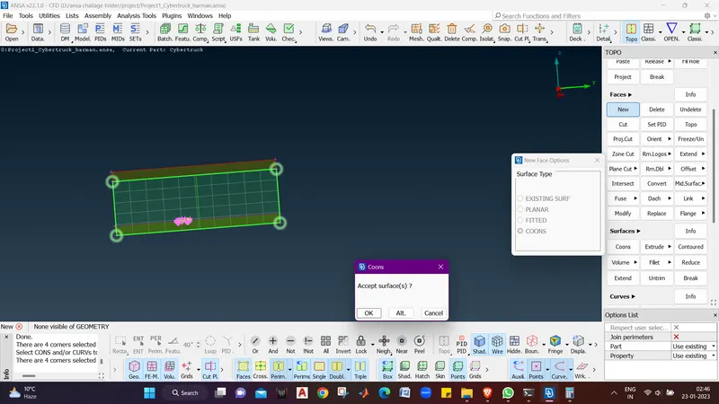
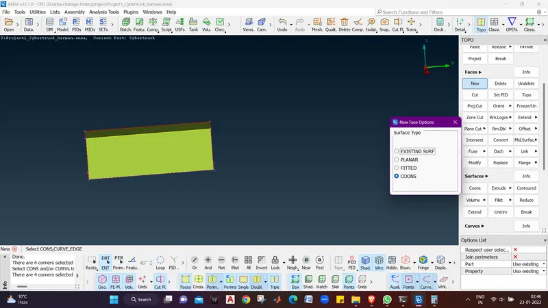
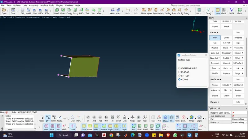
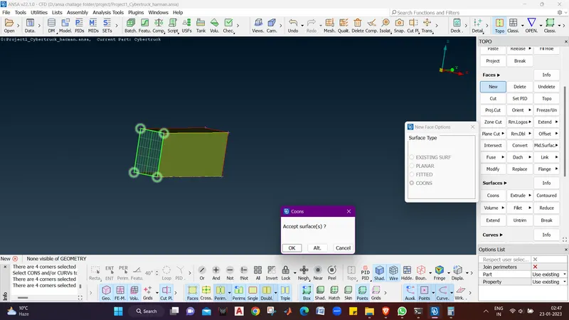
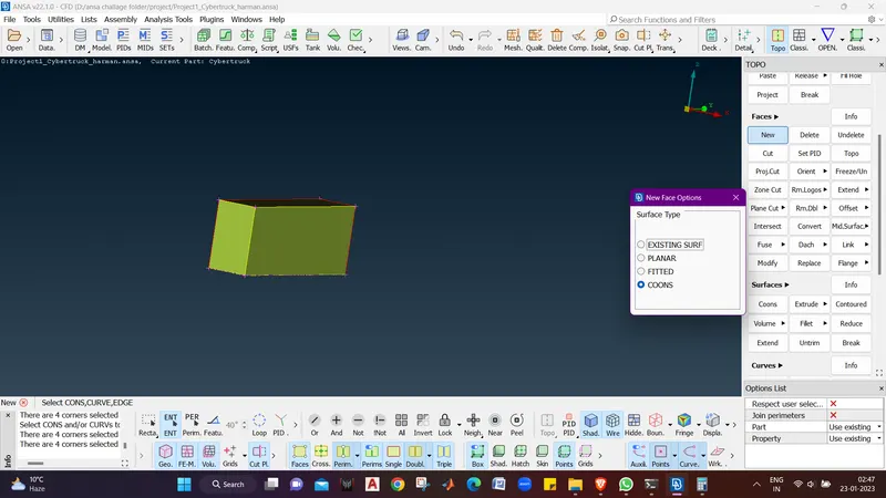
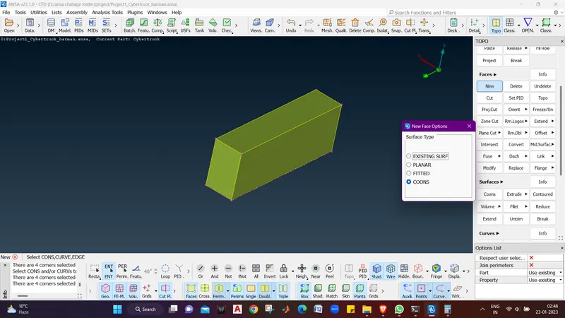
- Now we can see all the sides are made.
- We will assign them with different PIDs.
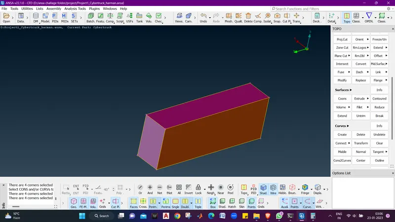
- Now we will hide all PIDs only leving the floor using NOT.
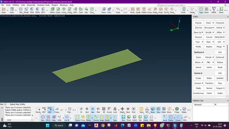
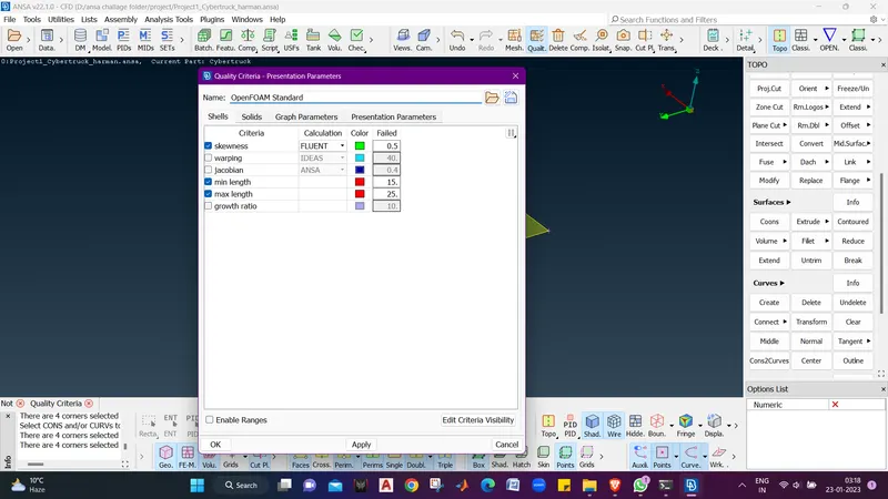
- Now we will give mesh and quality parameters for this surface in range 15-25 mm.
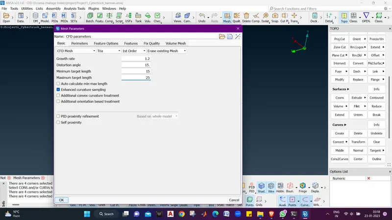
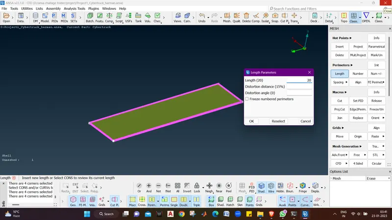
- Now we wil Assign target length as 20 in Macros and Parimeters.
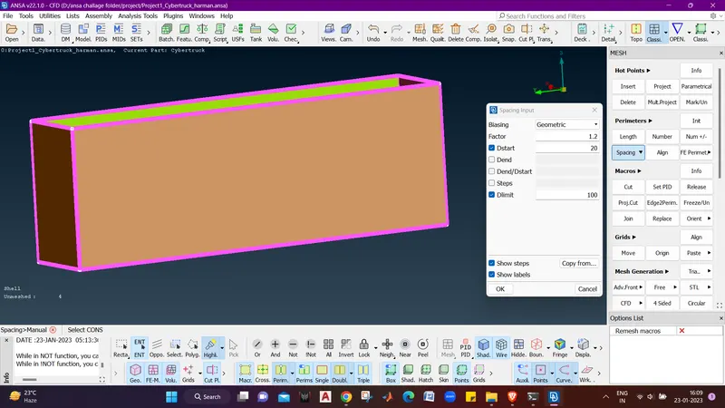
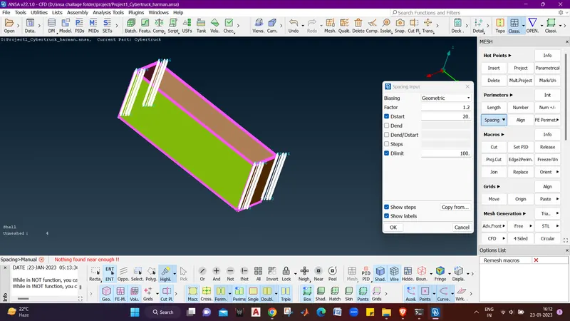
- Now For All the 4 sides we will use PERIMETERS - SPACING - DSTART ( 20 mm) - DLIMIT (100 mm) and click ok.
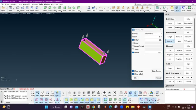
- Now for the top surface we will assign the Target length as 100 mm for macros and perimeters.
- Now as we have assigned target length to all the PIDs of wind tunnel we will go For spot mesh - Select and middle click.
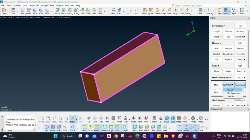
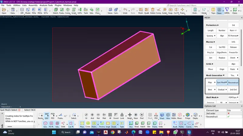
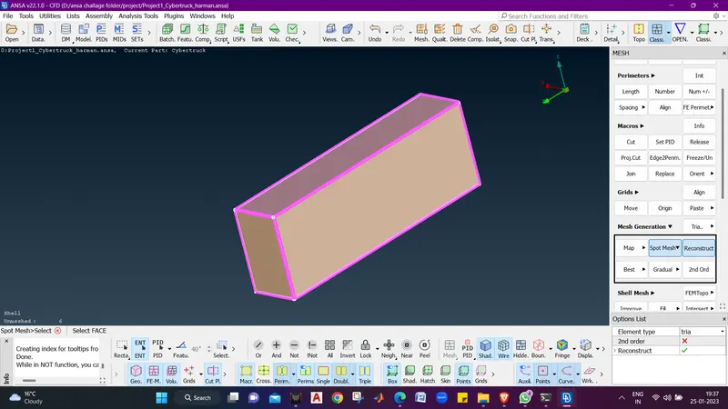
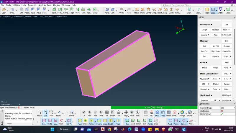
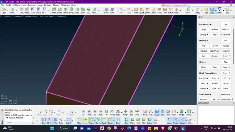
- we can see that we have meshed the wind tunnel with 0 off elements.
- Now we will go for volumetric mesh as we have no unmeshed part.
- Switch to volumetric mesh mode.
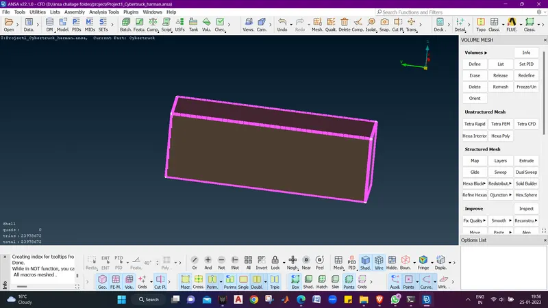
- Now we will define volumes using VOLUMES - DEFINE.
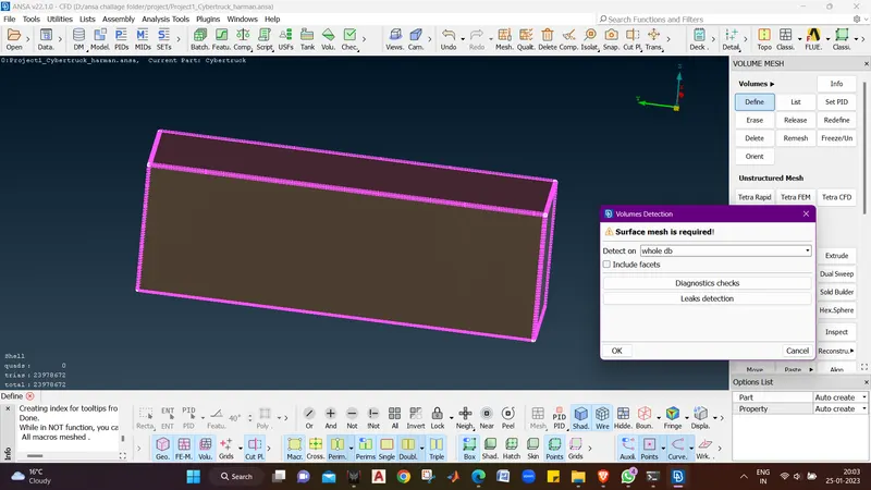
- click ok and it will show the volumes.
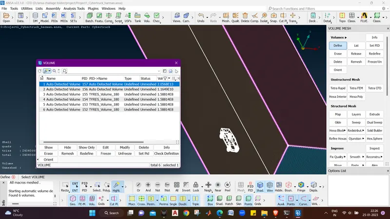
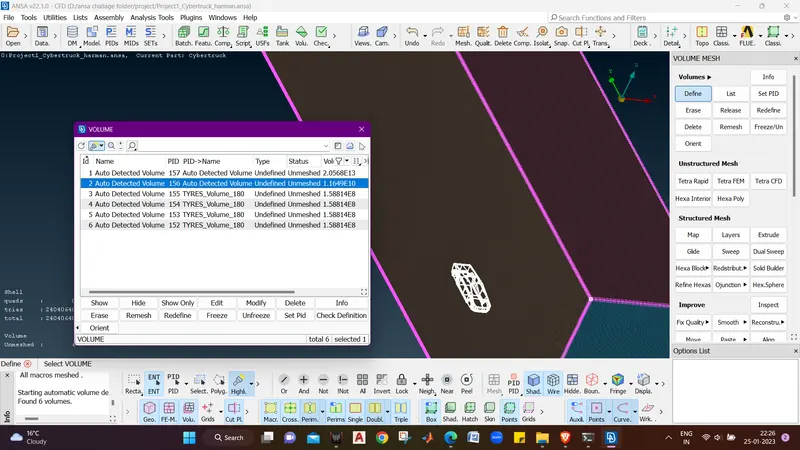
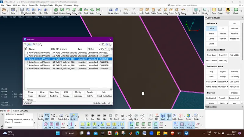
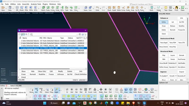
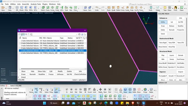
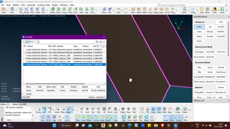
- Now we can see that it shows 6 volumes out of which we don't need the 2nd ,3rd ,4th, 5th and 6th volume so we will delete the volumes.
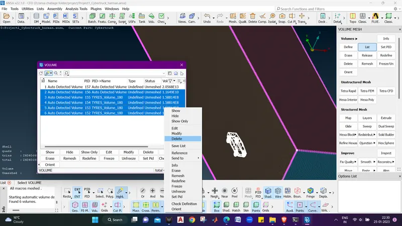
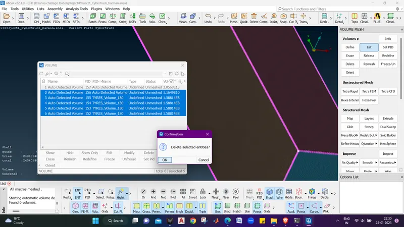
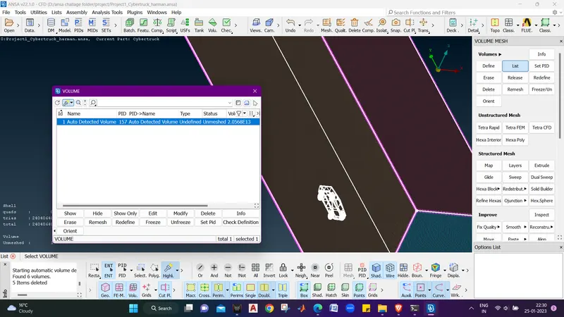
- Now select the volume, right click on it and select remesh.
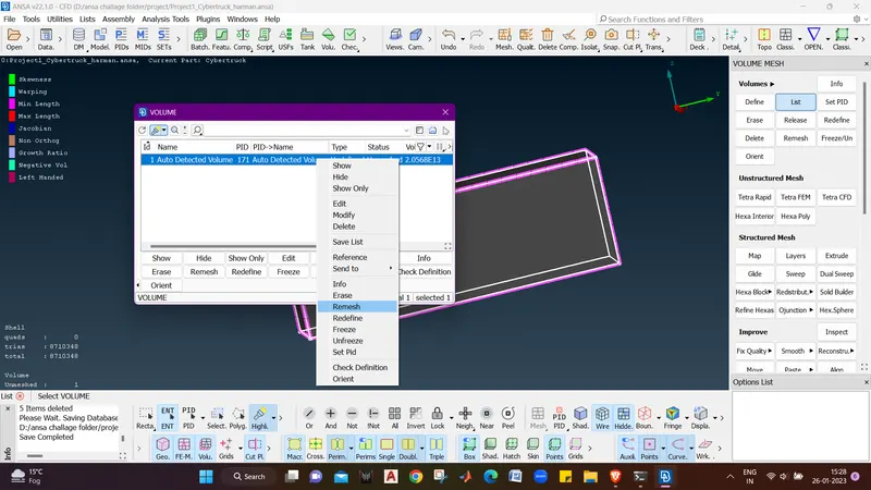
- I tried the meshing but my system is crashing after 50 percent.
LEARNING OUTCOME :-
From this project we came to know the computational time totaly depends on the quality criteria , if we give a bigger range the time taken will be less and there is less channces of error while meshing and there should not be any peniteration ot geometrical error while meshing which may result in ba mesh.
RESULT :-
The tesla cyber truck have been meshed properly with adjusting the over all quality criteria as 1-110 mm which include the wind tunnel too.
The link for the model is
https://drive.google.com/file/d/11lCroGtuumADV3bl8INsTWrdHFrnx7ET/view?usp=share_link
Conclusion :-