Week 2 Challenge : Surface meshing on a Pressure valve
Aim:-Meshing a Pressure Valve with target length(1,3 & 5mm) and Element type(tria)
Procedure :-
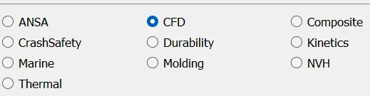
- First open the ANSA 2022 Software and select CFD domain.
- Select CFD module in the dialog box.
- Click and open the help button to copy the -performance_mode 3

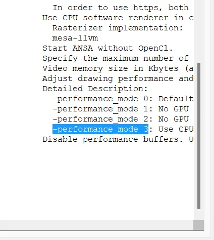
- Now copy the highlighted -performance_mode 3.
- Now paste the (-performance_mode 3)in the Other box.

- Now by clicking ok the GUI interface open on the screen
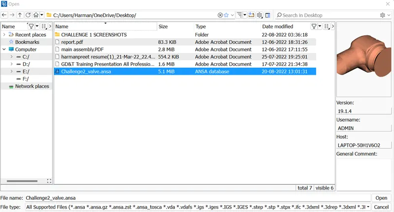
- Now use open to browse the file to be opened for meshing.

- Now selected the file and click on open , the file will be opened in the ANSA GUI .
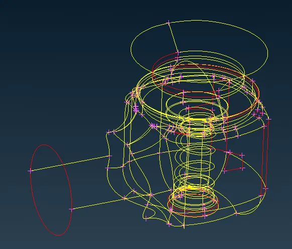
- The Pressure Valve appears in wire frame mode.
- Now we will click on shaded button to make the pressure valve to view in solid form.
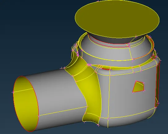
- At present we are in topo mode where we can do the geometry clean uo by using different tools.
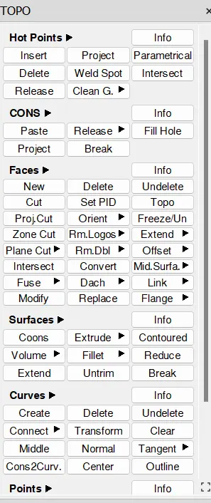
- There are 3 types of CONS
RED CONS :- it represents a surface which is not conneced to other face.
YELLOW CONS :- it represents two surfaces joininf on a line.
BLUE CONS:- it represents 3 surfaces line joining at one edge.
*Now we will do the geometry cleanup.
- We wiil first go for the Geometry Check in the CHECKS MANAGER.

- Select GEOMETRY_CHECK in the template window and double click on it.
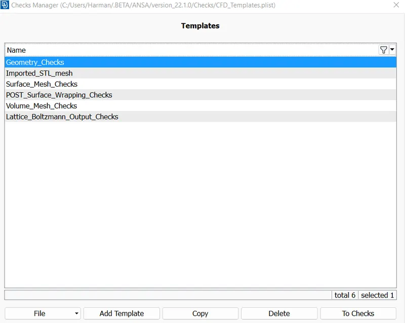
- The dialogue box appears, Select EXECUTE to find out the geometry errors.
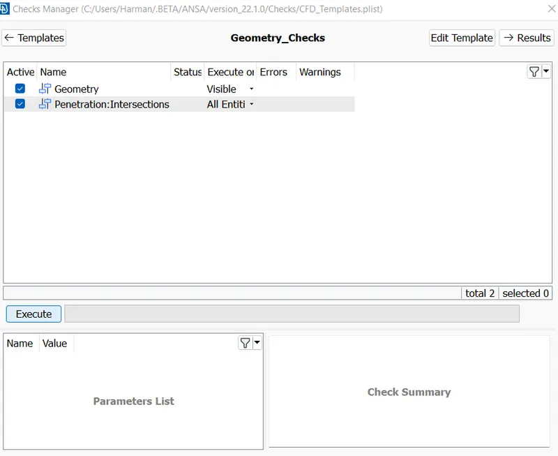
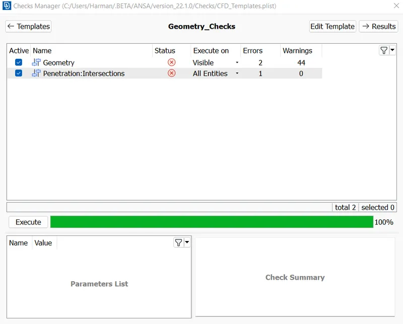
- As we can see there is a geomtry error and Penetration (intersection) error.
- so we will first do the geometry cleanup for the geometry errors.
- We will use faces tool bar for body cleanup.
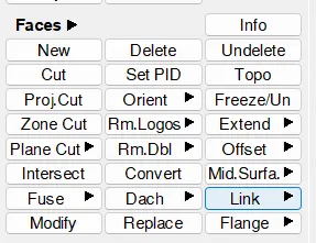
- we have red cons and yellow cons in the model.
- we have hot points too.
- First we will use topo command for the removing extra and repairing the model so that there is less cleanup to do.
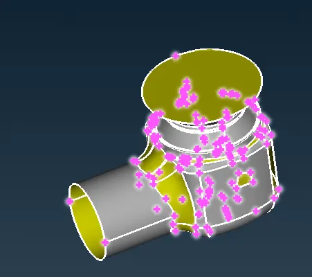
- select with box selecton and middle click of the mouse.
- topo cammand is execeted.
- NOw we have to deal with the open serfaces creating red cons.
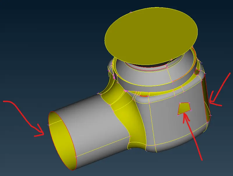
- Using New we will remove the red cons by making surfaces.
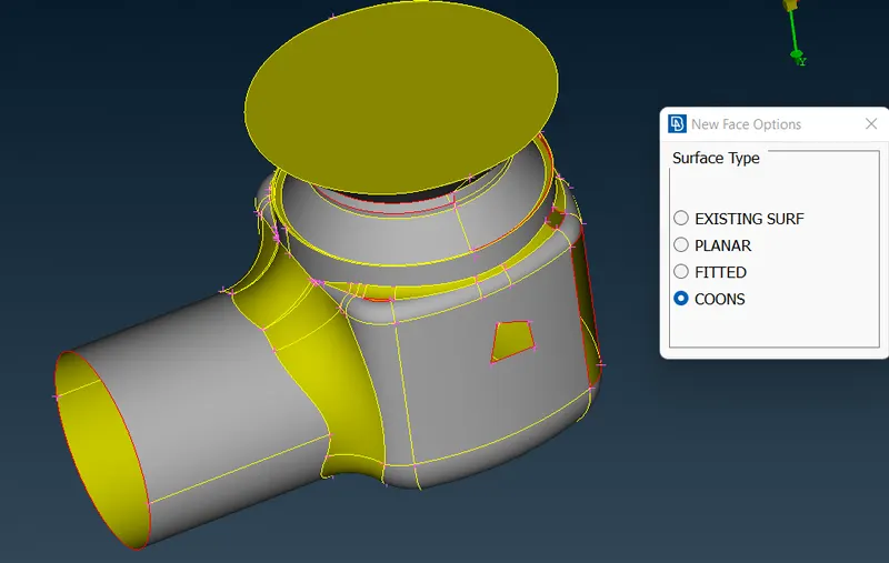
- It contain 4 options:-
- Existing surface :- in this command we can select a open surface and then select an adjacent surface thesurface will be created
- Planar :- This command is only used where the adjacent surfaces are perpendicular or at some angle and the surface have no curvature in cons
- Fitted :- This command is used very rare. its mosty good for planer surfaces.
- coons :- This command is the best command , can be used in many ways for cleanng up the geometry especially with loop opton.
- one more option is there for the geometry cleanup and thats flll hole. althought i won'twork on wavy surfaces much.
- now lets start cleaning up the model.
- We will first deal with the outlet part.
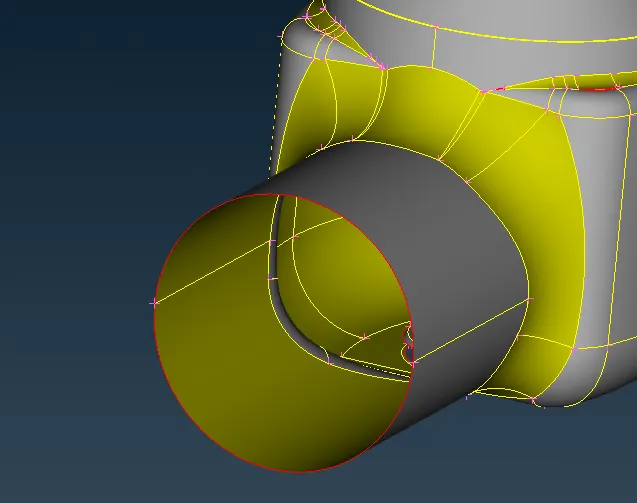
- we will use the fill hole option for making a surface over the outlet.
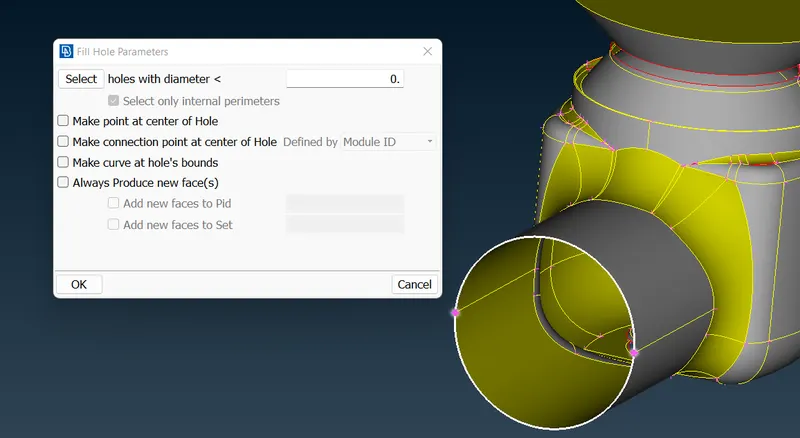
- We will select the cons where we want to have the surface. and click ok. The surface will be filled.
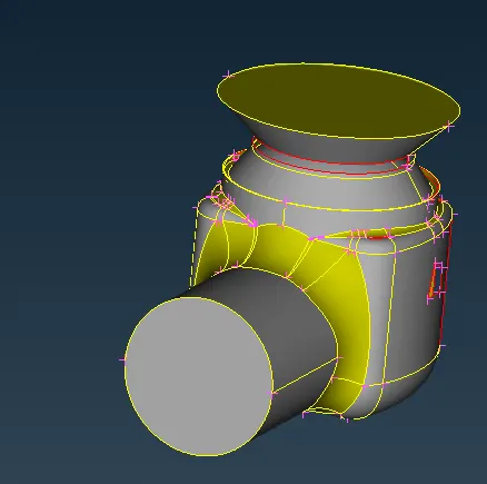
- like this we will fill all the surfaces. using New and filll hole tool.
- Body after surface cleanup.
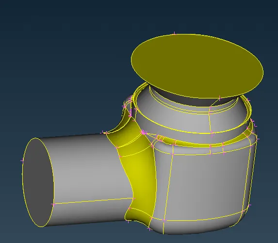
- NOw we will assign PIDs to the make differentiate components.
- we will use FOCUS tools for iding and unhideing the surfaces

- with OR (/) tool we can hide on unhide a surface by clicking on teh surface, rest surfaces will be hide or unhide.
- with AND(+) tool we can brong back surfacs that are hidden by clicking on the cons .
- with NOT (-) tool we can hide a surface we don't want at time of assigning pids or geometry cleanup.
- with !NOT (!-) tool we can hide a PID or surface and then using middle click we will only have the component we wanted.
- with All tool all the hidden surfaces come back on the screen.
- with LOCK tool we can lock the screen to disable all tool for unhiding the surfacea after the lock command,
- teh ALL command will only work after teh lock command id after the lock commsnd we have hidden some surface te surface will be unhide by the ALL command.
- The INVERT command elps in inverting the effect of any command like AND will work like NOT.
- The NEIGHb. command helps to unhide the neighbor surfaces by selecting a con.
- The PID assgigned are in the picture
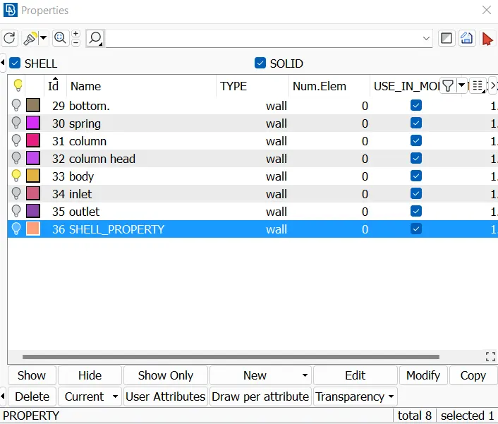
- Now we will delete the 36 SHELL_PROPERTY using the compress tool as the pid contains nothing in it and all the PIDs are assigned(Compress tool delete the PID or Entity permanently.)
- After deletin the PID we will have a gemetry checkup in the Checks Manager
- Now we will again go for geometry check to check if there is any intersection.
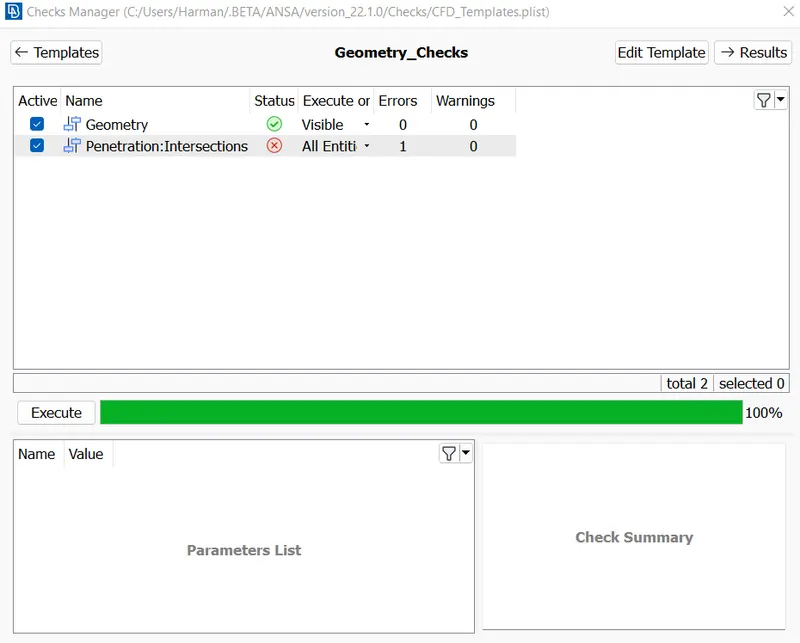
- now we can see that there is an intersection error.
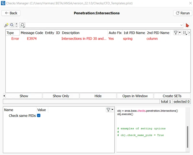
- The intersection is between Spring and Column PIDs.
- we will find it out by hiding the other pids by using NOT command in PID mode.
- we can see the intersection bte spring and COlumn in this pic.
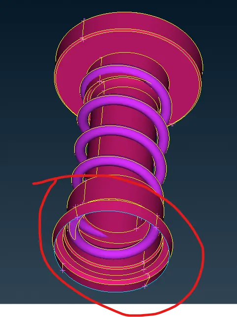
- We will remove it by using intersect command .
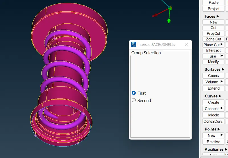
- fisrt we will select the spring and press the middle button to confirm it the color of the spring will change.
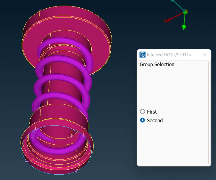
- now we will select the second component as the Column and press middle click.
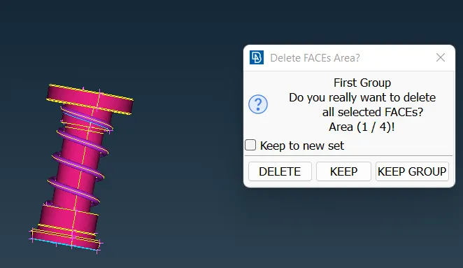
- here its showing 4 intersection surfaces.
- we have to delete intersecting surfaces which are not needed. after deleting the surfaces we have to again check for intersecting eroor.
- if errror is there, we can use another method.
- we can directly trim the surface by using cut tool for splitting one surface into two.
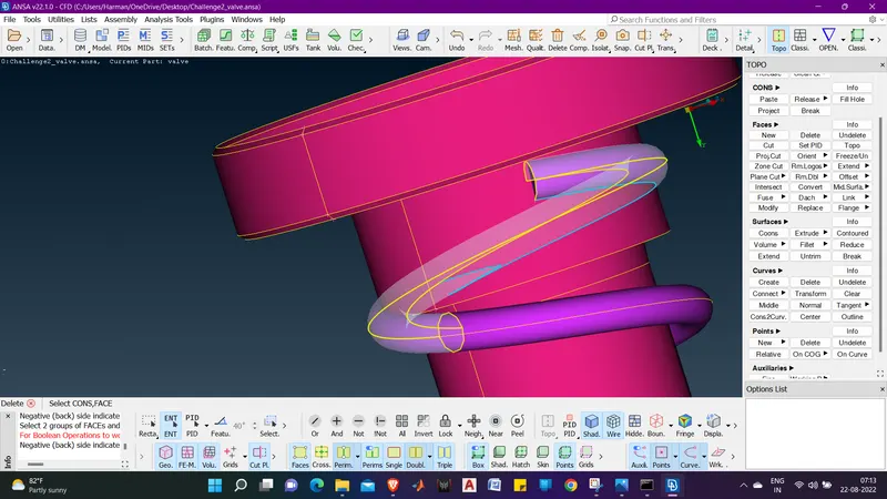
- Now we can delete the extra surface using Delete commmand.
- And the resultant file will look like the picture.
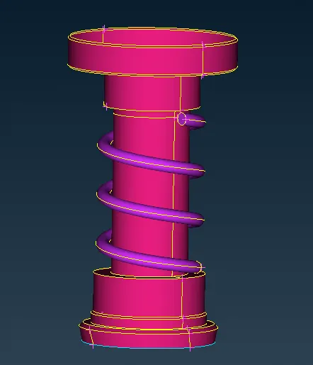
- Again checking for geometry and intersection error.
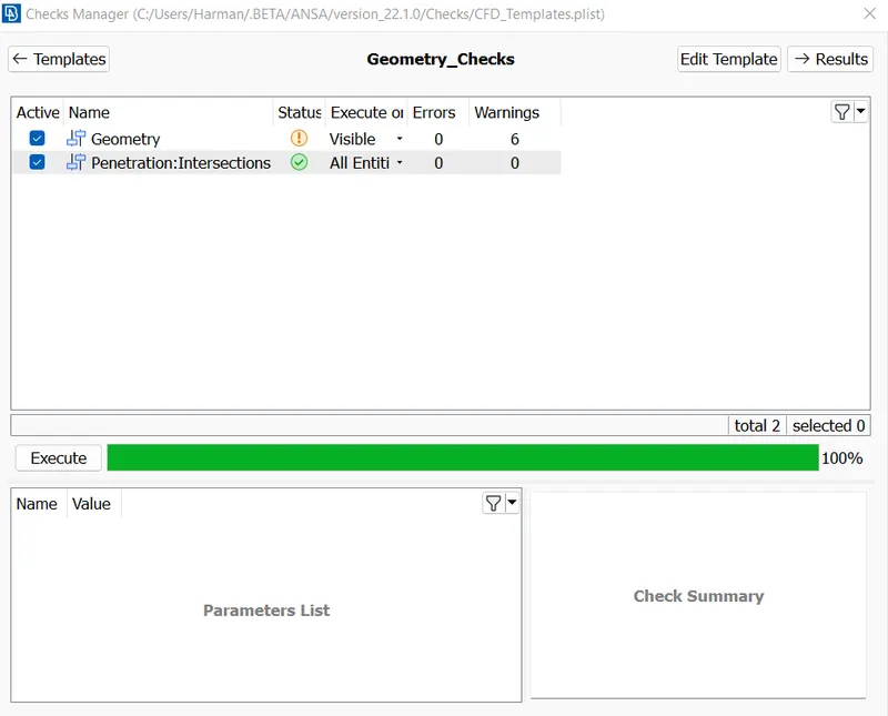
- There is no error now we can proceed for meshing the model.
*Now we will do the meshing of the model in 3 different target length with tria as the element type.
- We will click on classic mesh for opening the meshing tools
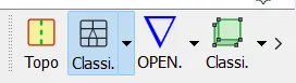
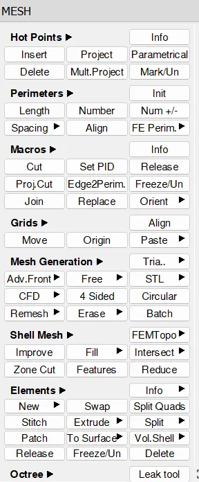
- And change mode to mesh by switching mode from topo to mesh.
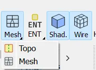
- We will first assign the target length by clicking on length in Perimeters tool box.
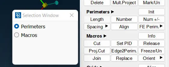
- Now with box selection select the whole model and press middle click of mouse.
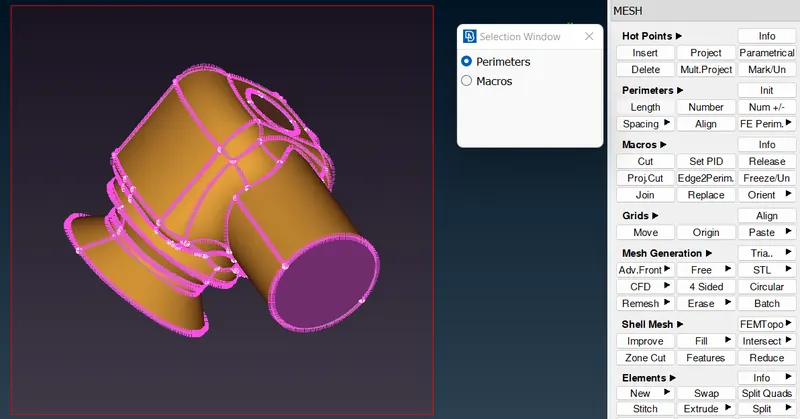
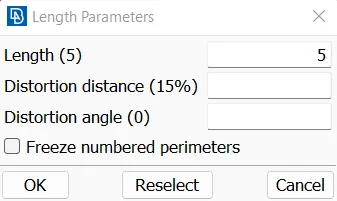
- Now set the target length to 5 mm and middle click of mouse.
- And now check macros and do the box selection
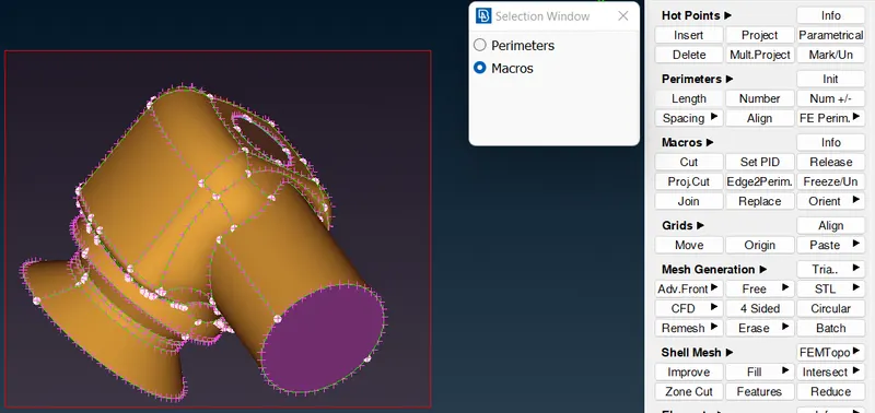
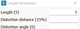
- Again middle click the mouse and give target length 5 mm.
- Again middle click to end the command.
- Now we have to set mesh parameters and quality criteria.
- Click on MESH PARAMETER button .

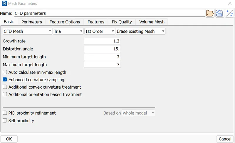
- The MESH PARAMETERS dialogue box opens. Set MINIMUM TARGET LENGTH to 3 mm & MAXIMUM TARGET LENGTH to 7 mm, set ELEMENT TYPE to TRIA and click ok.
- Now Click on quality criteria.

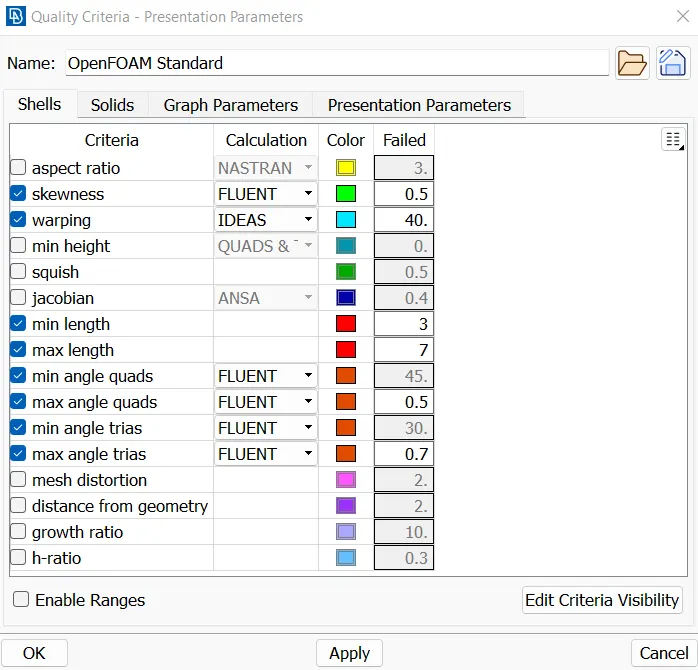
- In the dialog box select MINIMUM LENGTH as 3 mm and MAXIMUM LENGTH as 7 mm and click ok.
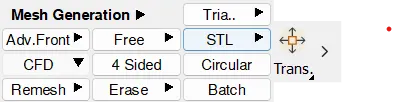
- Now click on the mesh generation tool box and right click select spot mesh or can select CFD mesh as CFD mesh is more accurate.
- And select the model with box selection and middle click to mesh the model.
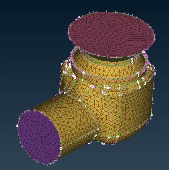
- The mesh is done.
- Now we have to check the mesh of inner components. so we will hide the outer body using PIDs selection.
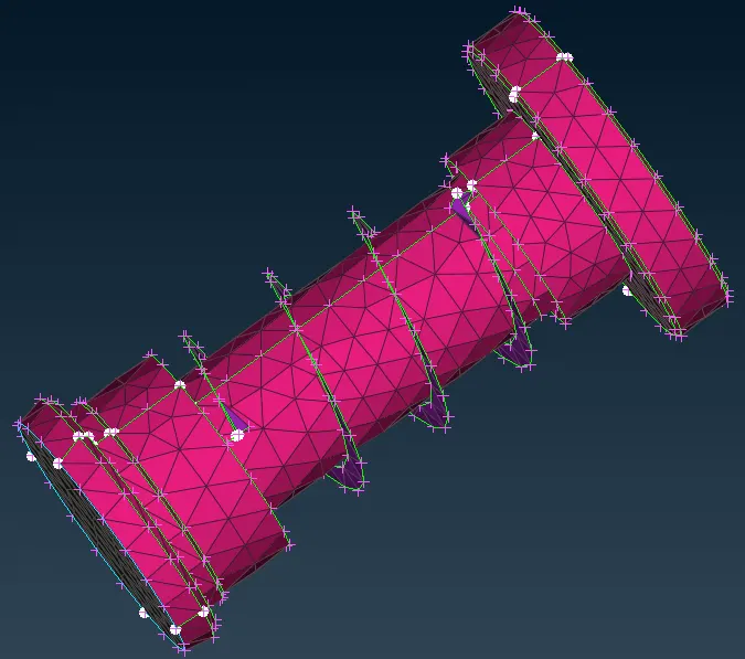
- After hiding the outer body we came to know that we have amajor failure in spring mesh and little bit of the column mesh is distorted.
- As the mesh in the spring is showing only a plane surface it have failed the mesh.spring shape shoild be circular in mesh then only the mesh will be considered.
- Now lets try for the 3 mm mesh.
- before moving to the 3 mm mesh we have to erase the mesh, so that there is no overlapping of mesh structure
- make a box selection to select the whole model after selecting the erase command and press the center mouse button to end teh command.
- and click on ALL comand to unhide all the surfaces.
- We will first assign the target length by clicking on length in Perimeters tool box.
- Now with box selection select the whole model and press middle click of mouse.
- Now set the target length to 3 mm and middle click of mouse.
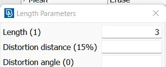
- And now check macros and do the box selection
- Again middle click the mouse and give target length 3 mm.
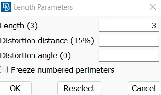
- Again middle click to end the command.
- Now we have to set mesh parameters and quality criteria.
- Click on MESH PARAMETER button .
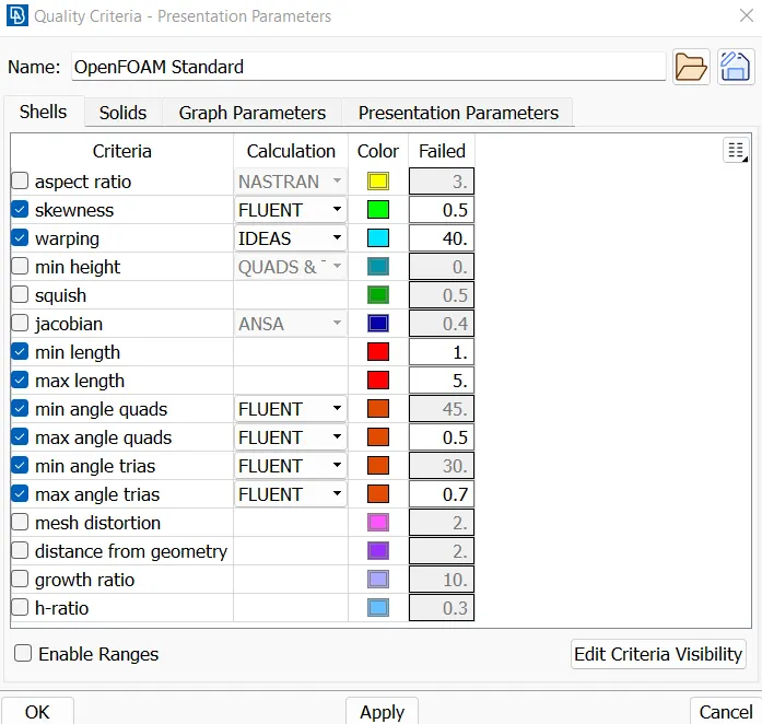
- The MESH PARAMETERS dialogue box opens. Set MINIMUM TARGET LENGTH to 1 mm & MAXIMUM TARGET LENGTH to 5mm, set ELEMENT TYPE to TRIA and click ok.
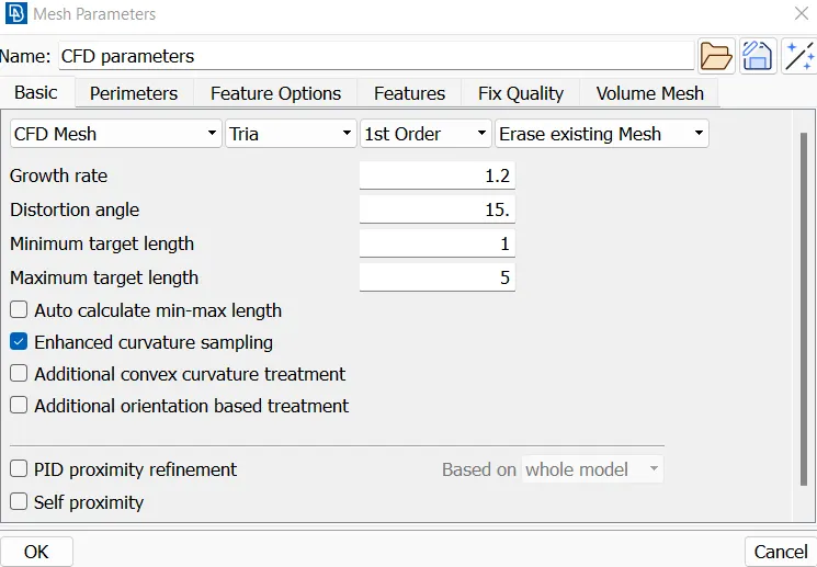
- Now Click on quality criteria.
- In the dialog box select MINIMUM LENGTH as 1 mm and MAXIMUM LENGTH as 5 mm and click ok.
- Now click on the mesh generation tool box and right click select spot mesh or can select CFD mesh as CFD mesh is more accurate.
- And select the model with box selection and middle click to mesh the model.
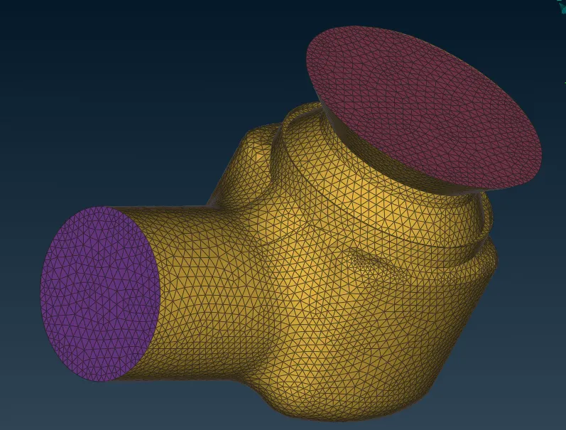
- The mesh is done and better than before on the outer body.
- Now we have to check the mesh of inner components. so we will hide the outer body using PIDs selection.
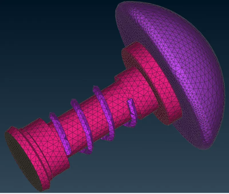
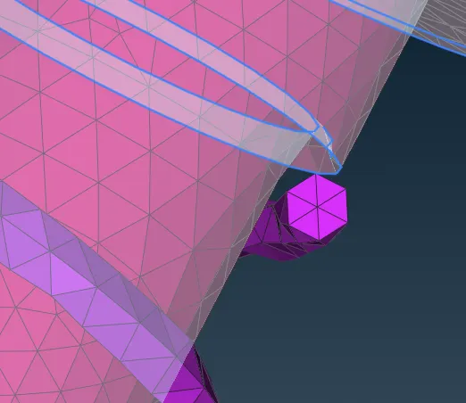
- After hiding the outer body we came to know that we have failure in spring mesh is distorted.
- As the mesh in the spring is showing hexagonal shape ,which is not the orignal ptofile of spring as it should be round in apperance.
- Now lets try for the 1 mm mesh.
- before moving to the 1 mm mesh we have to erase the mesh, so that there is no overlapping of mesh structure
- make a box selection to select the whole model after selecting the erase command and press the center mouse button to end teh command.
- and click on ALL comand to unhide all the surfaces.
- We will first assign the target length by clicking on length in Perimeters tool box.
- Now with box selection select the whole model and press middle click of mouse.
- Now set the target length to 3 mm and middle click of mouse.

- And now check macros and do the box selection
- Again middle click the mouse and give target length 3 mm.
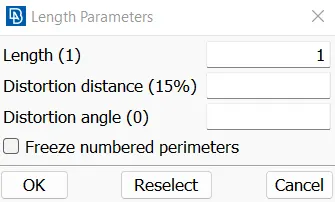
- Again middle click to end the command.
- Now we have to set mesh parameters and quality criteria.
- Click on MESH PARAMETER button .
- The MESH PARAMETERS dialogue box opens. Set MINIMUM TARGET LENGTH to 0.5 mm & MAXIMUM TARGET LENGTH to 1 mm., set ELEMENT TYPE to TRIA and click ok.
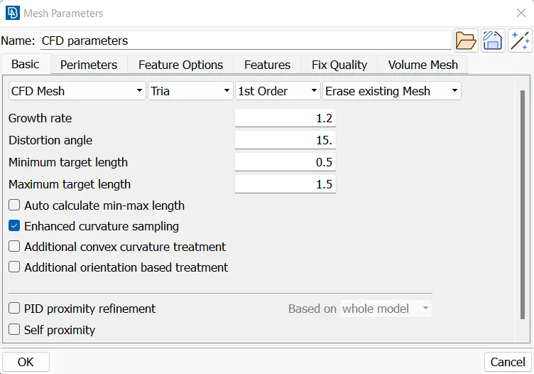
- Now Click on quality criteria.
- In the dialog box select MINIMUM LENGTH as 0.5 mm and MAXIMUM LENGTH as 1.5 mm and click ok.
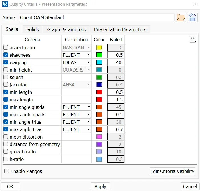
- Now click on the mesh generation tool box and right click select spot mesh or can select CFD mesh as CFD mesh is more accurate.
- And select the model with box selection and middle click to mesh the model.
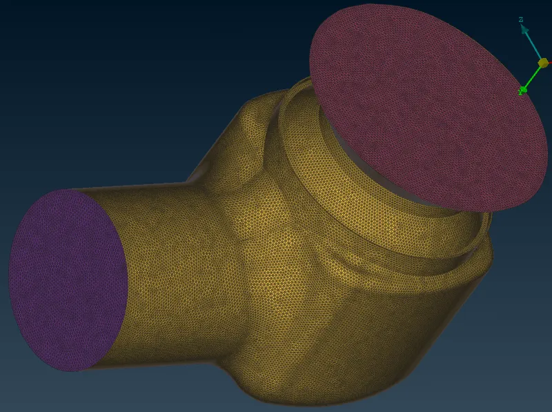
- The mesh is done and very fine mesh on the outer body is created.
- Now we have to check the mesh of inner components. so we will hide the outer body using PIDs selection.
-
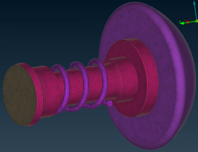
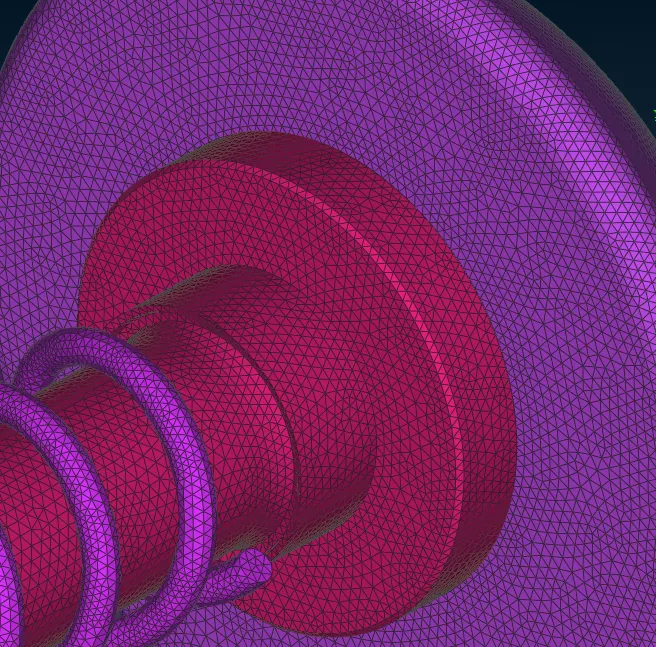
- After hiding the outer body we came to know that we have better mesh as compares to 3mm mesh.
- As the mesh in the spring is showing circular shape ,which is the orignal ptofile of spring as round in apperance.
- Now our mesh is now passed.
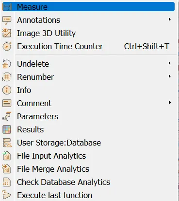
- now we can meassure the nodes length with Measure tool.
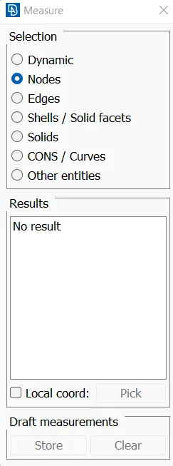
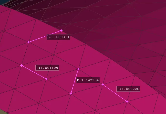
- As we can see the mesh length is btw 1-1.5.
- the mesh is sucessfull visually and prectiacally too.
From this we learned that before mesing we should check the geometry parameters like shape and do the geometry cleanup then mesh the model in a range to get better results and better mesh.
Result:-
The mesh model for all the three target length and element type is ready.
Conclusion:-
The basic Idea behind meshing the pressure valve is to make us familiar with the meshing and geometry cleanup Quality criterian tools and knowing how we can mesh the model by using diferent methods. and also knowing theat the not ony mesh length is neccessary, other factors like mesh quality criteria and range for target length also plays a great role in maintaining a perfect mesh.