Week 3 - External flow simulation over an Ahmed body.
AIM: External flow simulation over an Ahmed body.
OBJECTIVES:
- Describe Ahmed's body and its importance.
- Explain the reason for the negative pressure in the wake region.
- Explain the significance of the point of separation.
- Velocity and pressure contours.
- Run the simulation for the velocity of 25 m/sec with the default air properties in fluent.
- Perform the grid independency test and provide the values of drag and lift with each case.
Ahmed body :
The Ahmed body is a simplified car body used in the automotive field to study the impact of the flow pattern on the drag. The flow around the vehicle is characterized by high turbulent and three-dimensional flow separations. The Ahmed Body is a simplified car, used in the automotive field to investigate the flow analysis and find the wake flow around the body. The principal objective to study such a simplified car body is to tackle the flow processes involved in drag production
Importantance of Ahmed body:
An Ahmed body represents a simplified vehicle volume which helps understand the fundamental physics defined by the
engineers the lift and drag forces and coefficients at certain characteristically velocities, pressure differences, and seeing and
analyzing the vortices, turbulence, and Reynolds number obtained. ANSYS is a general-purpose FEA and CFD simulation
software. This model describes how to calculate the turbulent flow field around a simple car-like geometry using the Turbulent Flow, k-epsilon, and k-omega interface. Later, either experimentally or computationally it can be recreated all the same but with the desired geometry, new to come up to the market or research.
The wake was shown to be highly dependent on slant angle. For slant angles less than 12°, the flow remains attached over the slant. The flow is essentially two-dimensional and has low drag. Between 12° and 30°, the flow becomes much more three dimensional as the c-pillar vortices form. These reach maximum strength at 30°. The drag increases significantly as the low-pressure cores act on the rear surfaces. Past 30° the flow separates fully off the slant. This results in a sudden decrease in drag and weaker c-pillar vortices.
Reason for negative pressure in the wake region:
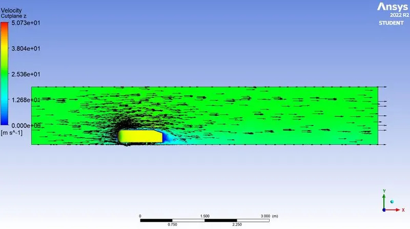
The path lines showing the exact circular motion or vorticity generation just at the rear end of the car. The separation takes two regions of distribution. One at the upper part of the rear and the other at the lower part of the rear end. The path lines show the nature of the fluid interaction with the rear end of the Ahmed body which here shows that the fluid just after leaving the contact from the slope still possess the momentum in it and the fluid particles near to the surface almost show the no-slip region which means the very least possible velocity of the fluid particles is in contact with the slope and base of the rear part. Thus the fluid particles away from the rear region having the higher pressure beside the wake region try to approach from the higher pressure region to the lower pressure region thus creating a circularity exactly in the wake region created.
Significance of the point of separation:
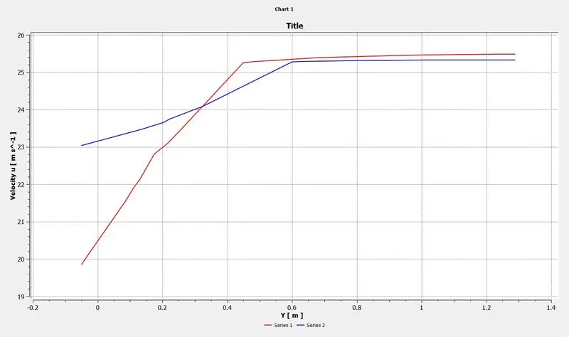
The fluid separation point can be defined as a point where the dv/dy i.e. gradient of velocity goes zero along with the dp/dx = 0, for the specific point. In a more simplified term we can say that at the point where the velocity gradient goes zero and the pressure gradient along the x-direction goes zero the point of separations starts occurring or the negative pressure gradient starts forming after that point. The point of separation cannot be understood just by a single contour in a hard and fast way. It can be supportively studied with the help of the dp/dx plots or velocity plots w.r.t the Y direction and other such plots in which we can see the nature of such physical properties like dp/dx=0, and dv/dy=0 experiencing in a particular region of fluid and body interaction.
Baseline approach :
Using k-epsilon model
- Ahmed's body is loaded.
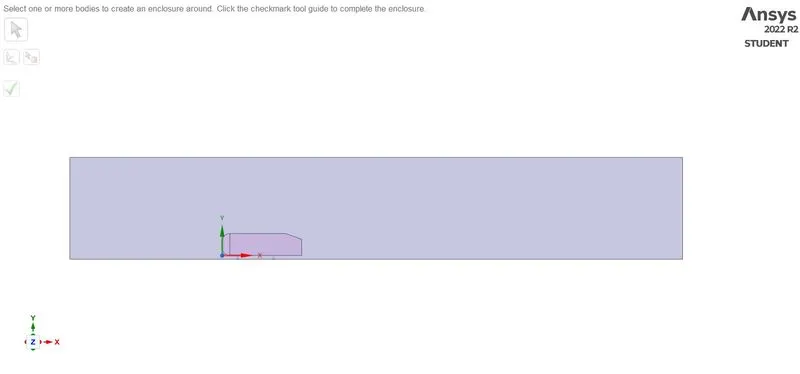
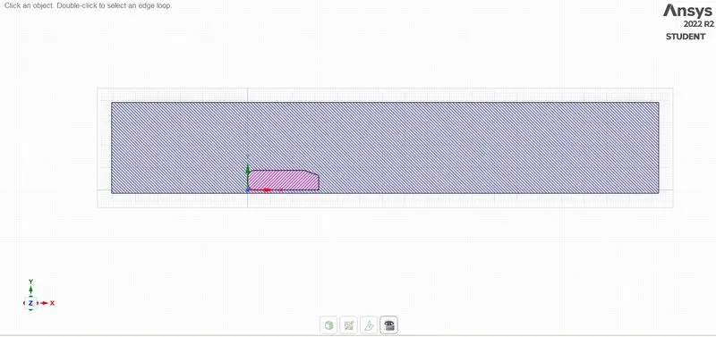
- A single rectangular enclosure is drawn across Ahmed's body.
- Now the geometry is loaded for meshing.
- A baseline simulation is set up with the default element size of Ansys.
- A named selection is created for the enclosure.
- Ansys Fluent window is opened and the geometry is loaded.
- Steady-state, the density-based solver is selected.
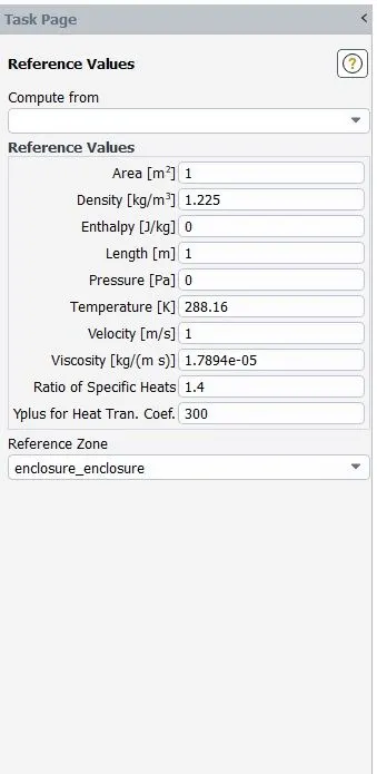
- Reference values are updated as per the prescribed conditions.
- In the inlet boundary condition, inlet velocity is 25m/s and 300K temperature are set.
- Drag-coefficient plot and lift-coefficient plot is created by setting the reference as (car walls).
- Hybrid initialization is selected.
- The solution is initialized by hitting t=0
t = 0 - The cut-plane-z is created along Ahmed's body.
- The velocity contour, pressure contour is created along the cut-plane-z.
- The animation video is created for the velocity contour.
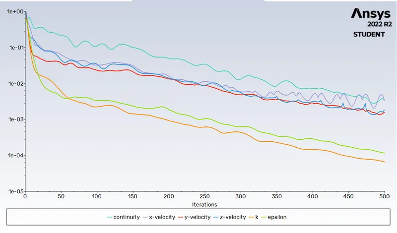
- The simulation is executed for 500 iteration.

CASE 1 :
Meshing is done for the body
RESULTS:
Residual plot:
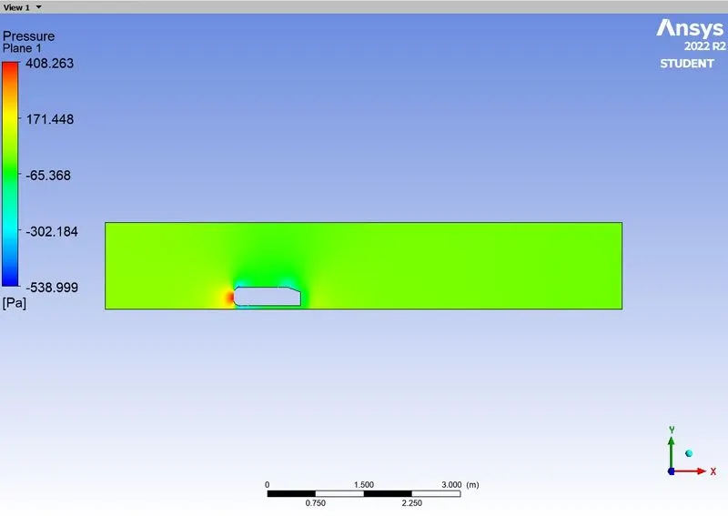
Pressure Contour :
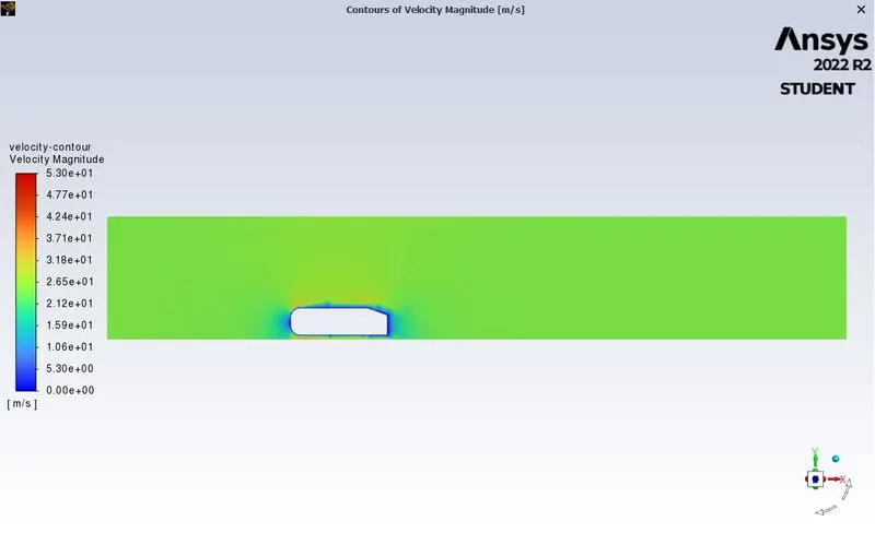
Velocity contour :
Velocity vector:
CASE 2 :
Refined with inner enclosure and refined mesh
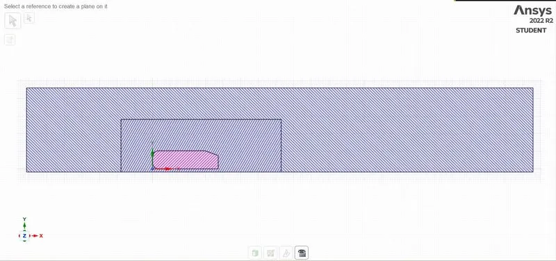
- Right face is located at a distance of 1 m from the right side face of Ahmed body along the X axis.
- Left face is located at a distance of 0.5 m from the left side face of Ahmed body along the X axis.
- Top face of the encloser is at a distance of 0.25m from the top side face of the Ahmed body along the Y axis.
- The bottom face of the encloser is attached to the bottom face of the Ahmed body along the YZ plane.
- The front and back face of the encloser is at a distance of 0.26 m along the Z axis.
Meshing:
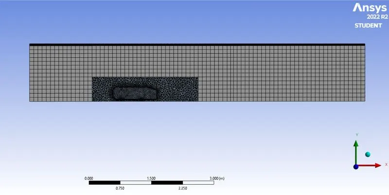
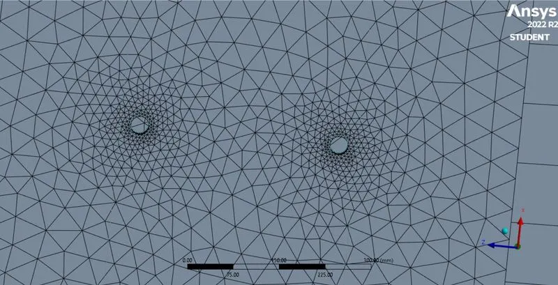
The Ahmed body is surrounded by a very fine hexahedral grid to record flow structures and inner enclosure is surrounded by tetrahedral grid and inflation layers are created along the walls of ahmed body to accurately capture the flow separation from its rear.
Solver setting :
- Type of solver: Density-based
- Simulation method: Steady-state simulation
- Turbulent Model: k-epsilon standard
- Material properties of the fluid (Air)
Density: 1.225 kg/m3
Cp (Specific heat): 1006.43 J/kg-k
Thermal Conductivity: 0.0242 w/m-k
Viscosity: 1.7894e-05 kg/m-s
- Inlet velocity: 25 m/s
- Inlet Temperature: 300 K
- Outlet: Pressure type, 0-gauge pressure.
RESULTS:
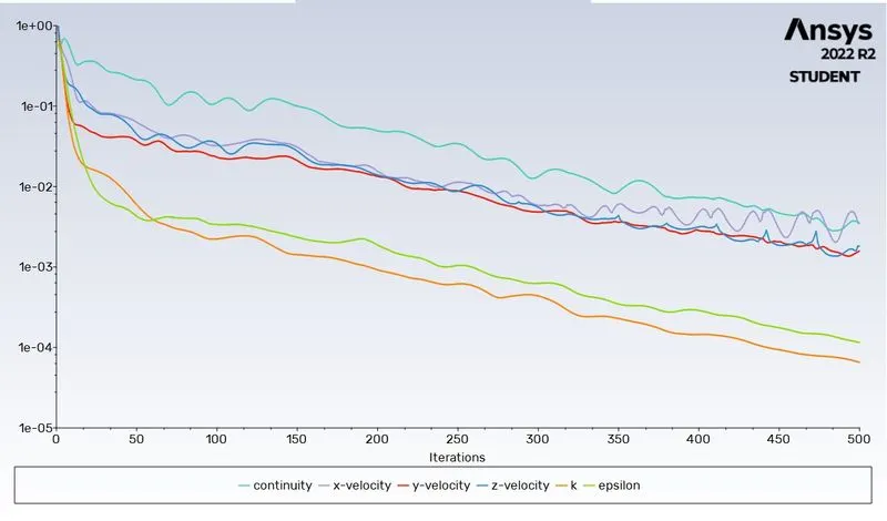
Residual Plots:
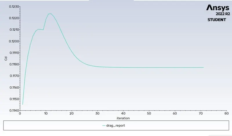
Coefficient of Drag:
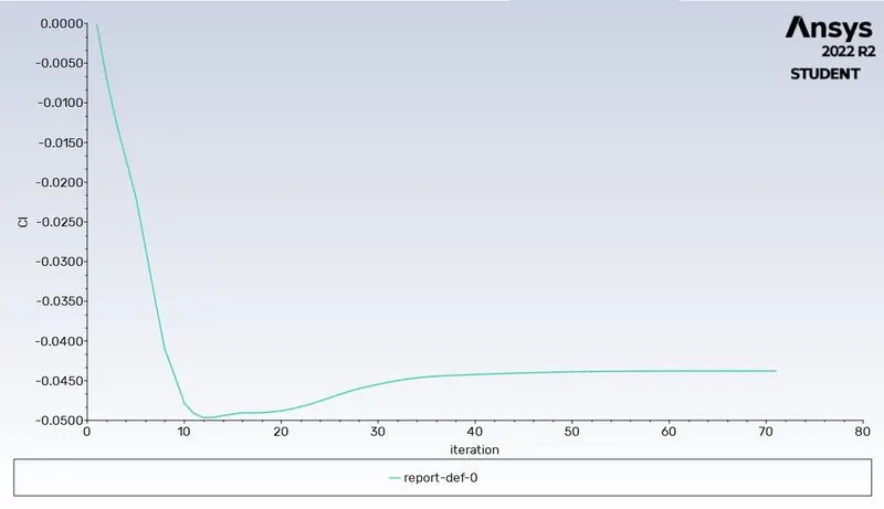
Coefficient of Lift :
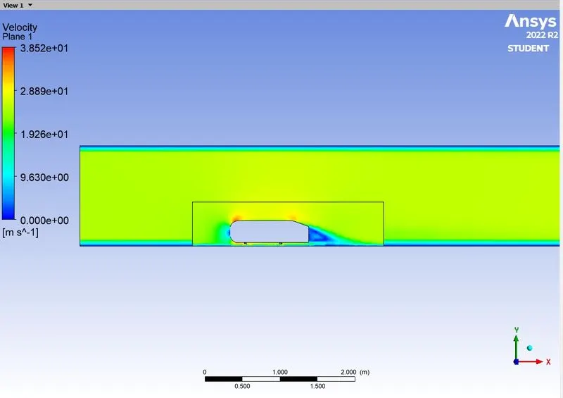
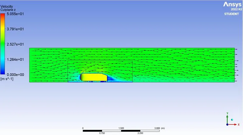
Velocity contour :
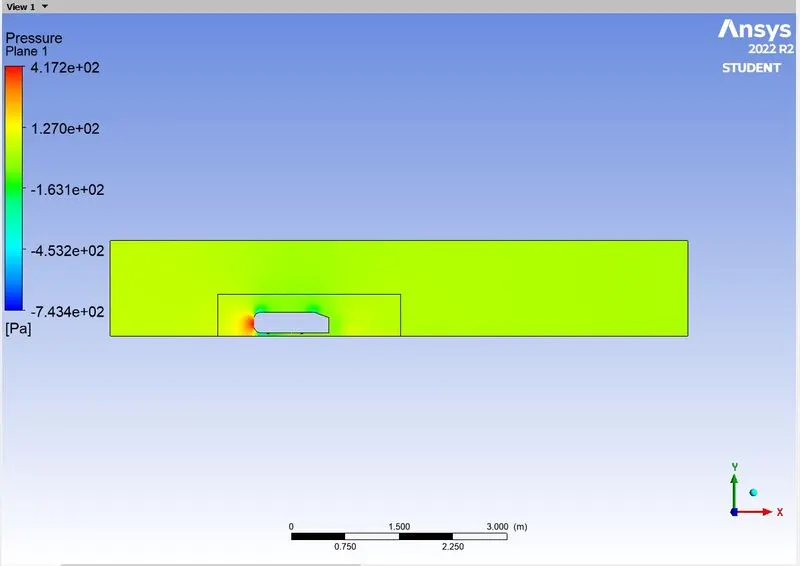
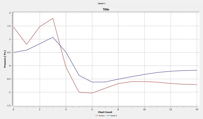
Pressure Contour:
Velocity Vector:
Grid independence test:
drag co-efficient(Cd) Lift co-efficient(Cl) No. of Iterations to Converged
32.431343 18.579436 165
0.048867 -0.006838 71
Conclusion:
- The baseline mesh gave a poor result, it wasn't able to capture the flow around the Ahmed body and the wake structure, due to coarse mesh.
- The refined mesh gave better results, The plots show the wake formation accurately and the flow around the Ahmed body was also captured pretty well.
- The reason behind negative pressure in the wake region is due to flow separation, and recirculating flow. It's a phenomenon that generally happens as the air moving past the body isn't able to pass through the immediate backside of the body creating a region, where there is no movement of air and thereby creating a pressure gradient.