Week 2 Challenge : Surface meshing on a Pressure valve
AIM :
To check for the geometrical errors and perform Topology cleanup accordingly. Set three different target lengths as three different cases and mesh the model.
PROCEDURE :
Import the model into the ANSA and we can see the some surfaces are missing from the model. To fill the missing surfaces use the TOPO module and do a topology check
- Fill the missing surfaces using the new face option ot the fill hole options
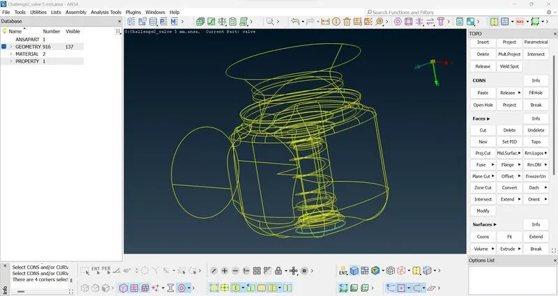
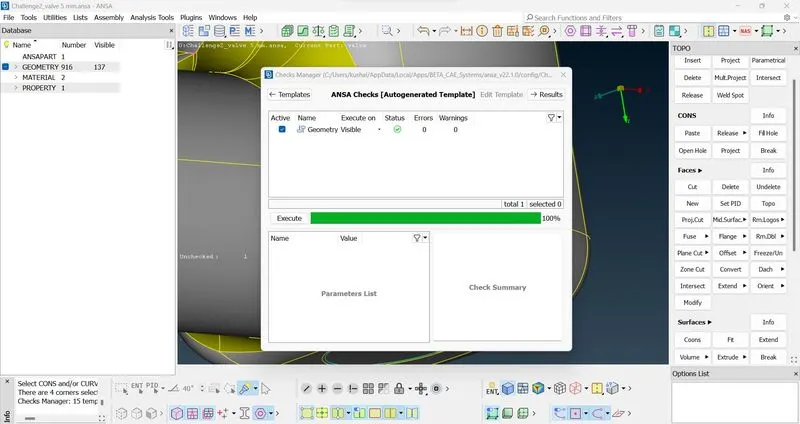
- Check for the geometry errors in the model and make sure that the errors are corrected, the result is shown in the figure below
-
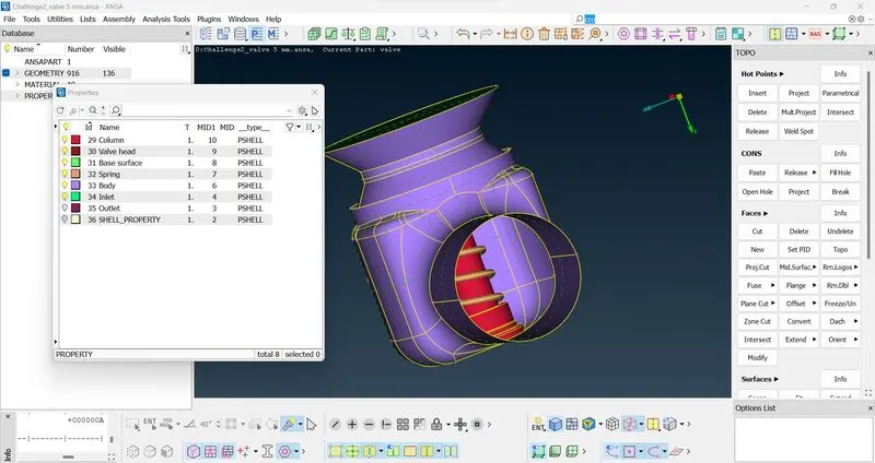
- Assign PID for each element in the model as shown in the figure below
MESHING :
Too start meshing follow the sequence before giving the lenght ( Parameters and Macros )
- MESH PARAMETERS -> QUALITY CRITERIA -> LENGTH
- Give the mesh parameter as 3mm and check the quality criteria.
- Give the length of parameters and macros as 3mm
- Select the entire body
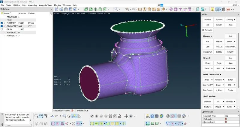
- Now with the help of spot mesh tool apply 3mm mesh for the entire model
- The created mesh is shown in the figure below
Case 1 : Target length 1mm
- From the PID properties menu hide everything except the element you have to mesh with 1mm
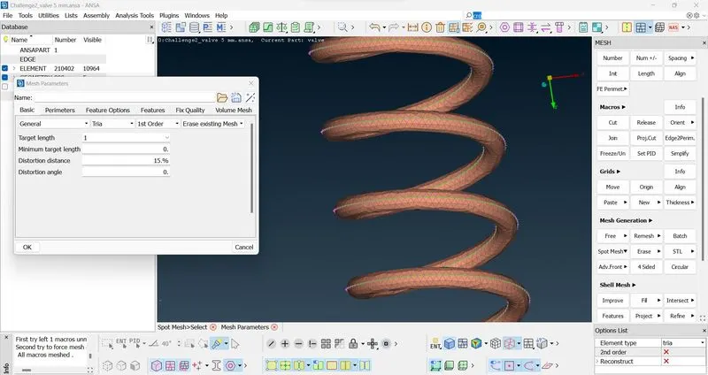
- From the given valve we have chosen the spring to give it 1mm target length
- Set the target length to 1mm in the mesh parameters
- Check that the element type is checked as tria
- Change the lenth of parameters and the macros to 1mm
- With the help to spot mesh tool select the spring and apply mesh
- The 1mm mesh created on the spring is shown in the figure below
Case 2 : Target length 3mm
- Now from the PID properties hide the spring and unhide the shell head which is to be meshed with 3mm
- Repeat the previous process
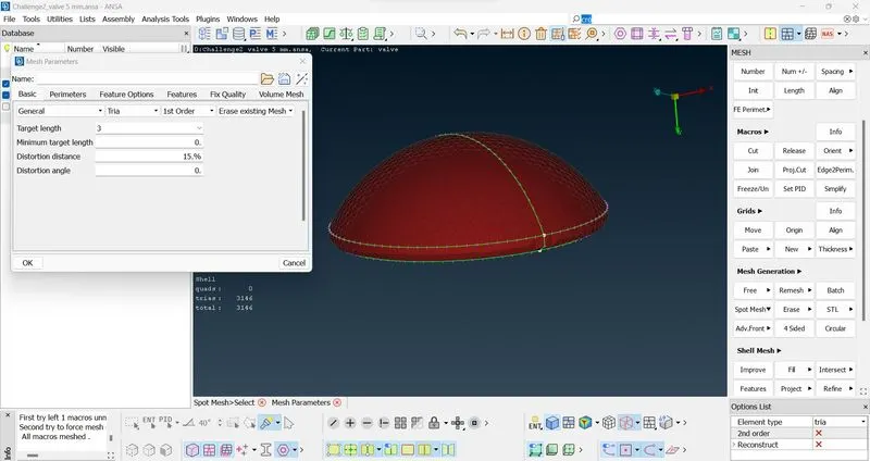
- Set the target length to 3mm in the mesh parameters
- Check that the element type is checked as tria
- Change the lenth of parameters and the macros to 3mm
- With the help to spot mesh tool select the shell head and apply mesh
- The 3mm mesh created on the spring is shown in the figure below
Case 3 : Target length 5mm
- Now from the PID properties hide the shell and unhide the column which is to be meshed with 5mm
- Repeat the previous process
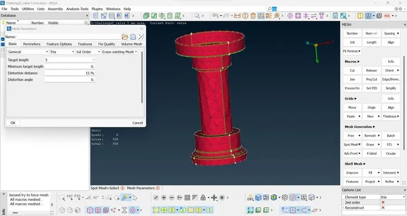
- Set the target length to 5mm in the mesh parameters
- Check that the element type is checked as tria
- Change the lenth of parameters and the macros to 5mm
- With the help to spot mesh tool select the column and apply mesh
- The 5mm mesh created on the spring is shown in the figure below
RESULT :
Case 1 i.e. when the target length is set to 1mm is giving good results
CONCLUSION :
From the above meshing process we have observed that, as the length of the mesh increases the structure and quality of the elements is changing. when we meshing with the different lengths for the different elements the desired results are obtained. Small mesh length for the elements having small dimensions. Here from the above discussion we came to know that the good mesh quality is given by the mesh length of 1mm it gives better accuracy for meshing. As we can see the other elements with increasing mesh length and comparing with the element having 1mm mesh from the above discussion