Week 3 Challenge : CFD meshing on Turbocharger
AIM :
To check for the geometrical errors to make appropriate volumes, Perform surface mesh with the given target lengths as per PIDs and Perform Volumetric mesh for the required volumes.
OBJECTIVE :
- Check the geometrical error
- Fix the single cons and triple cons error
- Create PIDs
- Assign PIDs
- Perform surface mesh with the given target lengths
- Perform Volumetric mesh for the required volumes.
PROCEDURE :
Import the model into the ANSA and we can see we can see the source file of the model where some surfaces are missing and some extra surfaces are having over lapped surfaces and some single cons and thriple cons.
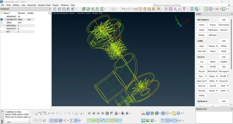
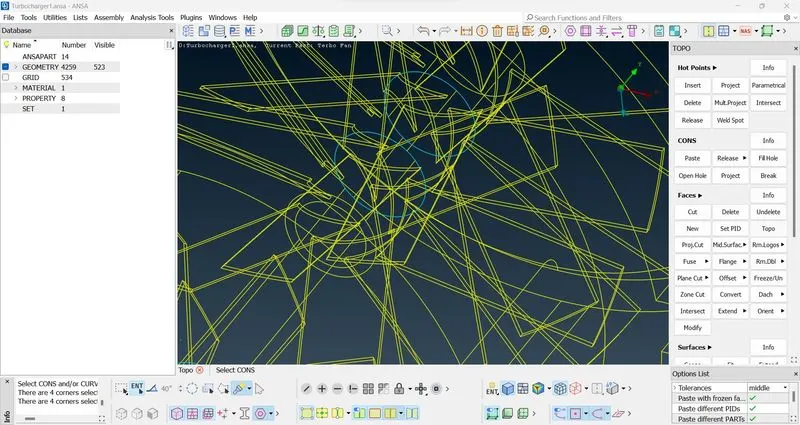
Reconstruct the missing surfaces of the turbo charger and delete the unwanted surfaces and overlappin surfaces do the geometric check and make sure that there are no single cons or unwanted triple cons are present in the model
Surface build :
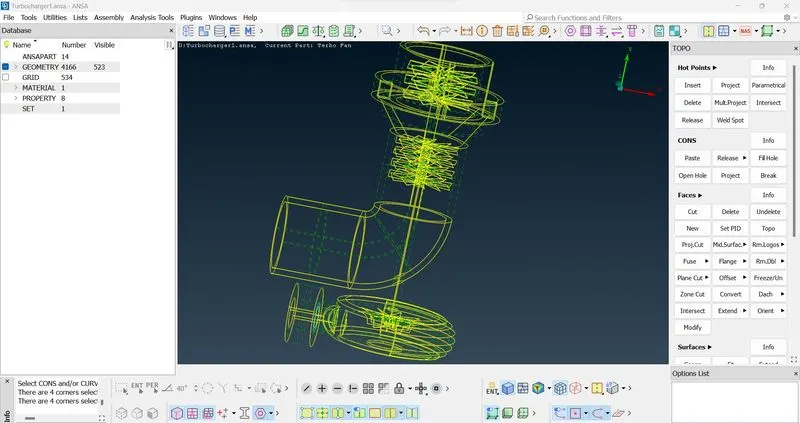
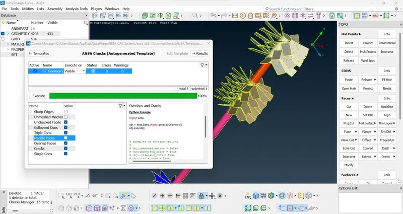
Case 1 : Assign PIDs
Assign PIDs for the excisting parts and create new PIDs for the created parts of the turbo charger
- Blade stage-1
- Blade stage-2
- Impeller
- Shaft rotor
- Turbo casing
- Compressor casing
- Inlet casing cover
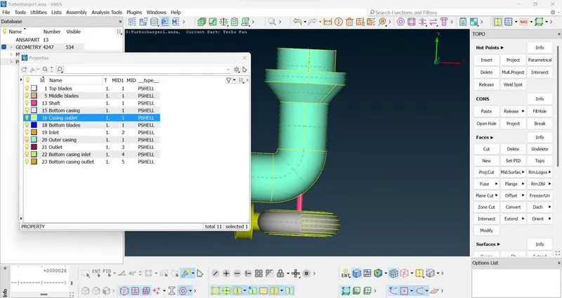
Case 2 : Perform surface mesh with the given target lengths
Too start meshing follow the sequence before giving the lenght ( Parameters and Macros )
- MESH PARAMETERS -> QUALITY CRITERIA -> LENGTH
Given target lengths as per PIDs.
- Blade stage-1 = 1 mm
- Blade stage-2 = 1 mm
- Impeller = 2 mm
- Shaft rotor = 1 mm
- Turbo casing = 5 mm
- Compressor casing = 5 mm
- Inlet casing cover = 5 mm
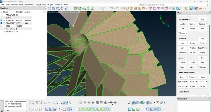
Blade stage 1 and 2 :
- Give the mesh parameter as 1mm and check the quality criteria.
- Give the length of parameters and macros as 1mm
- Select the blade stage 1 and 2
- Now with the help of spot mesh tool apply 1mm mesh for blade stage 1 and 2
- The created mesh is shown below
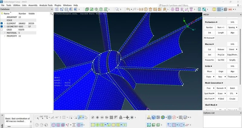
Impeller :
- Repeat the above process for the impeller with the target length of 2mm
- The created surface mesh is shown below
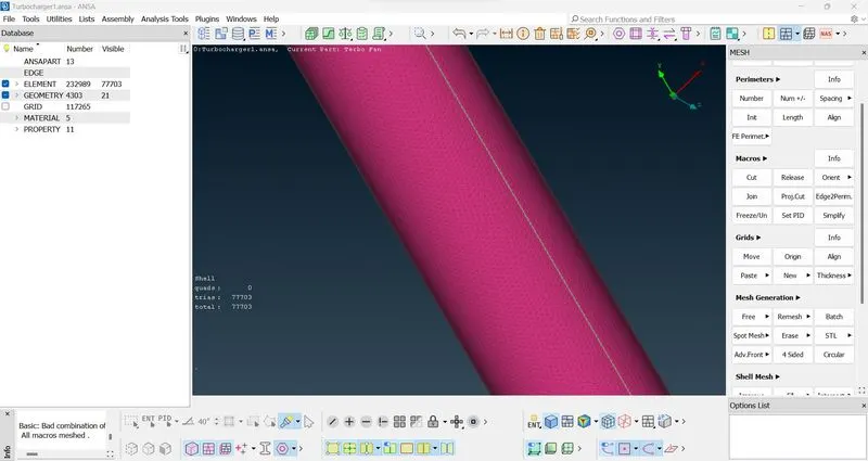
Shaft rotor :
- Repeat the above process for the shaft rotor with the target length of 1mm
- The created surface mesh is shown below
Turbo casing :
- Repeat the above process for the turbo casing with the target length of 5mm
- The created surface mesh is shown below
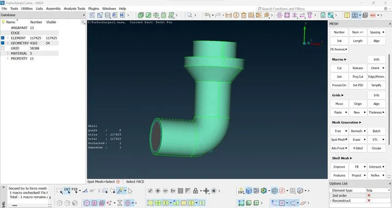
Compressor casing and inlet casing cover :
- Repeat the above process for Compressor casing and inlet casing cover with the target length of 1mm
- The created surface mesh is shown below
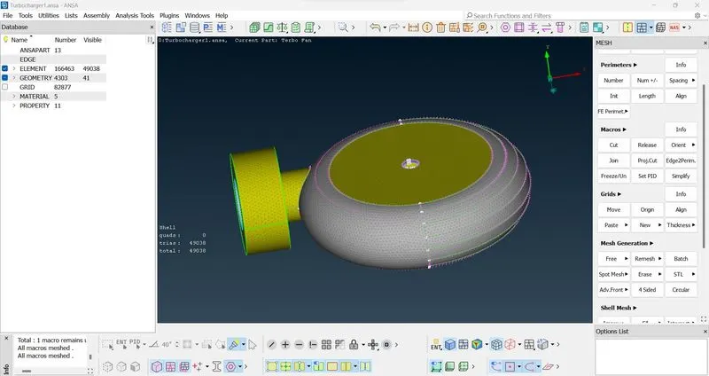
Complete surface meshed turbocharger :
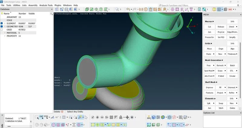
Case 3 : Perform Volumetric mesh for the required volumes
After the surface meshing, we can go to the volumetric mesh, we have to check first the errors in the surface mesh, after that, we can choose the option to define in the volume mesh which automatically detects the volume present in turbo charger. In the model where fluid is not flowing are unwanted volumes for the volumetric mesh, delete these volumes
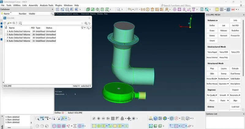
Now, after deleting the unwanted volumes of the turbocharger the remaining are the volumes to be volumetric meshed. Remesh the volume to tetra CFD. The status of the volume detected is changed to the tetra CFD as shown below
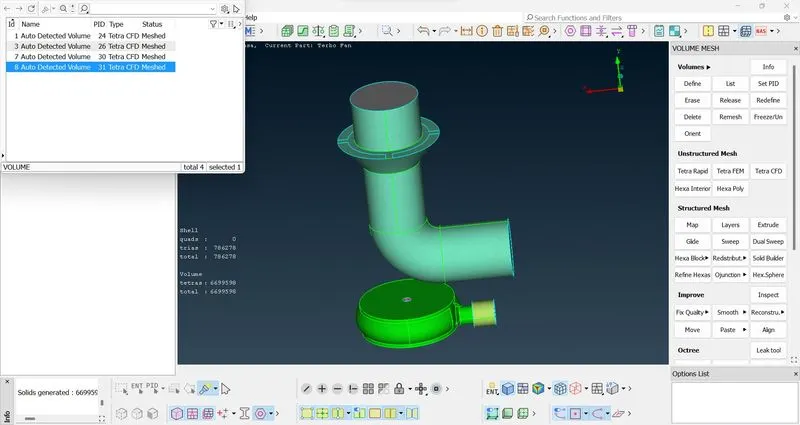
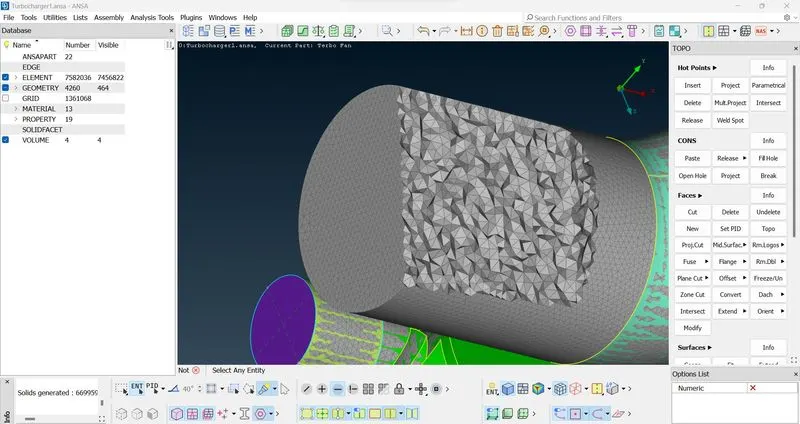
RESULT :
we can define the volumetric mesh which gives the number of elements in the turbo charger where the fluid is flowing, The length depends on the compression rate of the fluid.
Link to file :https://drive.google.com/file/d/1IrvGBIlbgGaqQeJvIchWVWGhVdEPrUo2/view?usp=sharing