Week 3 - External flow simulation over an Ahmed body.
Aim:
As the body is perfectly symmetric, we can run the simulation by considering the only half body. This is the best practice where you can save on the number of cells and get the results faster as well.
The geometry which is provided with the challenge needs a modification which you should be able to do at this stage of a course. You need to use the 'split body' command in SpaceClaim to perform the operation and then you can use the symmetry boundary condition in fluent to perform the simulation.
Run the simulation for the velocity of 25 m/sec with the default air properties in fluent.
- Describe Ahmed’s body and its importance.
The Ahmed body is a simplified car body used in the automotive field to study the impact of the flow pattern on the drag. The external aerodynamics of the car defines many major traits of an automobile like stability, comfort, and fuel consumption at high speeds. The flow around the vehicle is characterized by high turbulent and three – dimensional flow seperations as well as there is a growing need for more insight into the physical features of these dynamical flows. The Ahmed body is a simplified car, used in the automotive field to investigate the flows analysis and final the wake flow around the body. Ahmed body is made up of a rounf front part, a movable z slant plane in the rear of the body to study the detachment phenomena a different angles, and a rectangular box which link the front part and the rear slant plane. The principal objective to study such a simplified car body is to tackle the flow processes involved in drag production. Through perceiving the mechanisms involved in creating drag one can be able to design a car to minimize drag and therefore reducing fuel consumption and maximize vehicle performance.
Importance of Ahmed body:
An ahmed body represents a simplified vehicle volume which helps understand the fundamental physics defining by the engineers the lift and drag forces and coefficient at certain characteristically velocities, pressure differences and seeing and analyzing the vortices, turbulence, and Reynolds number obtained. ANSYS is a great – purpose FEA and CFD simulation software. It gives a numerical prediction of the behaviour of a system.
These numerical prerdictions need to be validated by experimental data. People working in vehicle aerodynamics use ahmed body to validate their numerical model because the experimental data from wind tunnel testing is available for ahmed body. Once the numerical model invalidated, it is used to design new models of the car.
It’s the shape is simple enough to allow for accurate flow simulation but retains some important practical features relevant to automobile bodies. This model describes how to calculate the turbulent flow field around a simple car-like geomentry using the turbulent flow, k-epsilon and k-omega interface. Later, either experimentally or computationally it can be recreated all the same but with the desired geomentry, new to come up to the market or research.
- Reason for negative pressure in the wake region:
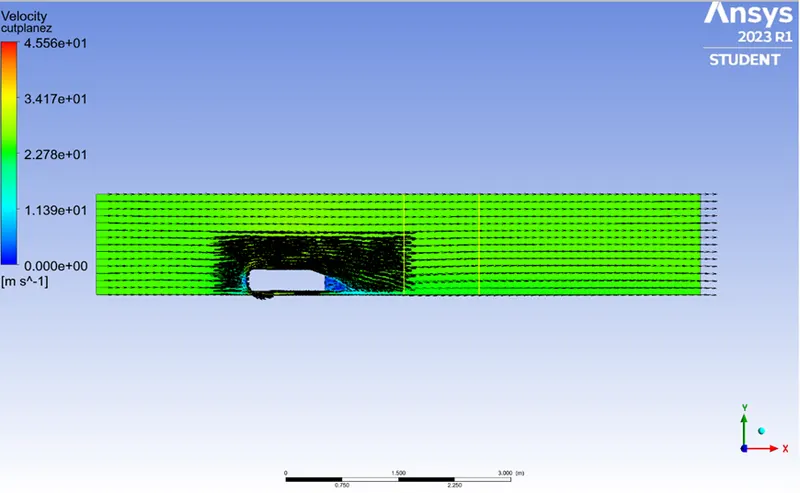
The path lines showing the exact circular motion or voracity generation just at he rear end of the car. The separation takes two regions of distribution. One at the upper part of the rear and the other at the lower part of the rear end.
The path lines show about the nature of the fluid interaction with the rear end of the Ahmed body which here shows that the fluid just after leaving the contact from the slope still possess the momentum in it and the fluid partices near to the surface almost show the no-slip region which means the very least possible velocity of the fluid particle is in contract with the slope and base of the rear part. Thus the fluid particles away frim the rear region having the higher pressure beside the wake region try to approach from the higher pressure region to the lower pressure region thus creating a circularity exactly in the wake region created.
- Significance of the point of separation:
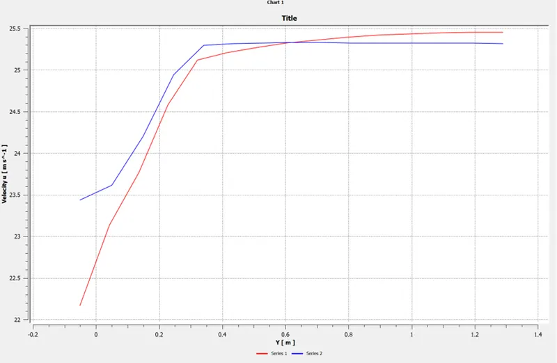
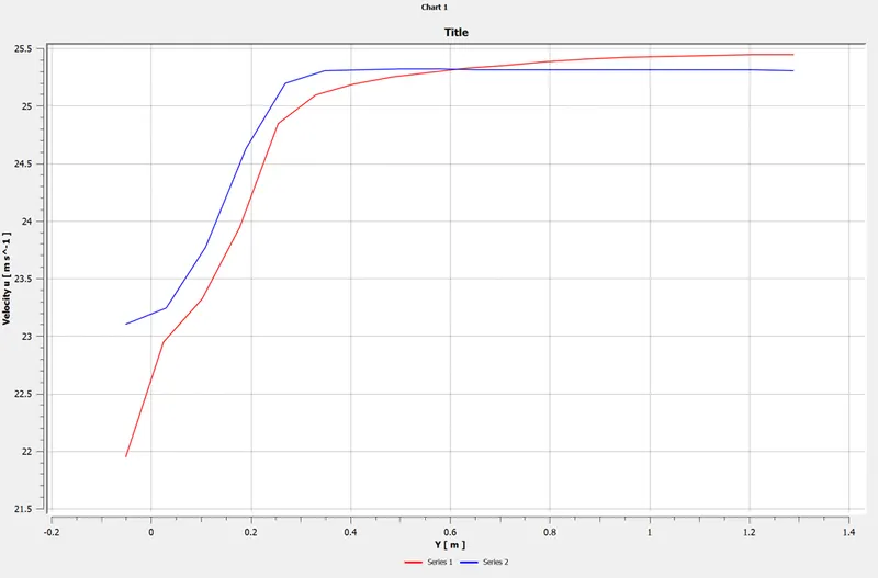
The fluid separation point can be defined as a point where dv/dy i.e. gradient of velocity goes zero along with the dp/dx = 0, for the specific point. In more simplified term we can say that the point where the velocity gradient goes zero and the pressure gradient along the x-direction goes zero the point of separations starts occurring or the negative pressure gradient starts forming after that point. The point of separation cannot be understood just by single contour in hard and fast way. It can be supportively studied with the help of the dp/dx plots or velocity plots w.r.t the Y direction and other such plots in which we can see the nature of such physical properties like dp/dx=0, and dv/dx=0 experiencing in a particular region of fluid and body interaction.
The body penetrating the fluid creates a region of emptiness just beside its end due to the nature of the geomentry of the body here which can be seen least in case of a perfectly streamlined shaped body. This emptinesss created is a low-pressure region towards which the fluid column exactly behind the wake region which of atmospheric pressure tries to fill the space thus dragging the fluid column with it thus creating the region of vorticity. This also results in the huge pressure gradient in the region exactly rear of the body creating the -ve pressure at the end. Also, this is the Layman’s reason why there is negative gauge pressure in the wake region.
- Geomentry :
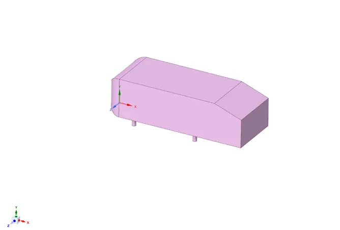
3d view Ahmed body
- Geomentry setup in SpaceClaim:
As the body is perfectly symmentric, we can run the simulation by considering only half the body. This is the best practice where you can save on the number of cells and get the results faster as well. The geomentry which is provided with the challenge needs a modification which you should be able to do at this stage of a course. You need to use the ‘Split body’ command in Space Claim to perform the operationand then you can use the symmentry boundry condition in fluent to perform the simulation.
- Load the Ahmed body model into SpaceClaim and convert the units from millimeters to meters.
- Go to prepare and click on the enclosure and select the Ahmed body. Enter the enclosure dimensions as shown snap. And uncheck symmentric option before giving the value.
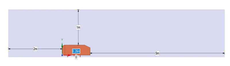
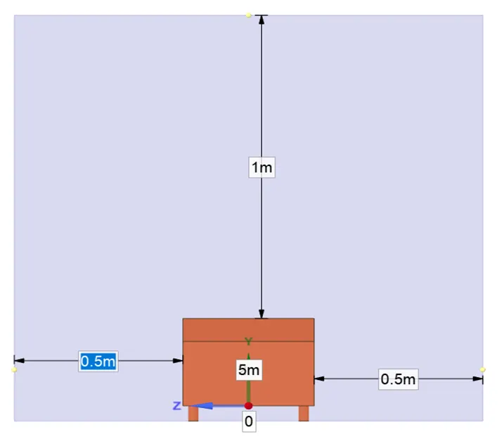
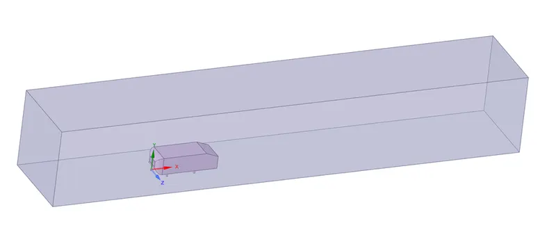
- Once the enclosure is done, we can create another enclosure closely around Ahmed body so that we can refine the mesh in that enclosure and still keep the total cell countless.
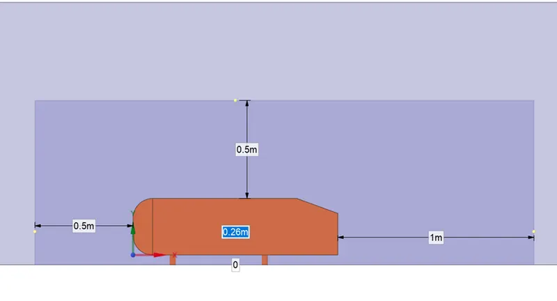 Ahmed body with inner and outer enclosure:
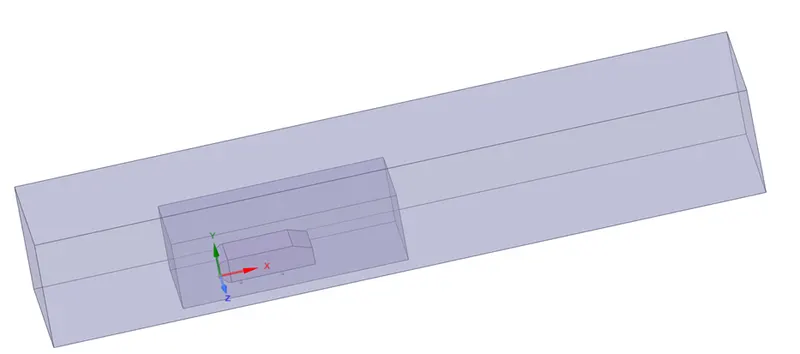
- After both the enclosure is created, we can check interference and avoid overlapping of meshing in the 2nd enclosure by applying check interference and deleting the overlap. This is automatically done by SpaceClaim when the interference option is selected inside prepare.
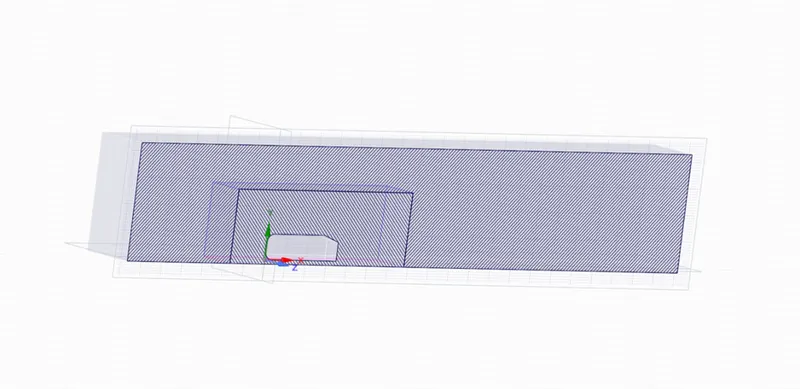
- After clearing the interference, we can now split the body in half using the split body command in design, but before that, we have to create a XY plane at the orgin to generate 2 equal halves. Select a design and choose planes and bring the cursor near the origin and left click. We get 3 planes, hide the unneccassary planes and use the XY plane. Choose split body and choose the enclosure needed to split, select the plane and choose the part needed to be removed. Similarly, we can achieve split on both the enclosures and the body.
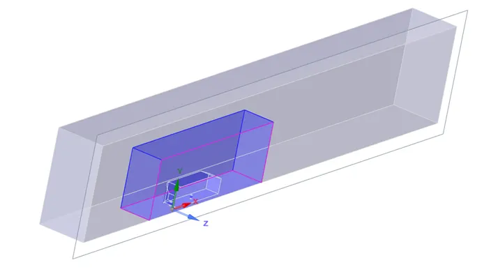
- After achieving the spilt, hide the ahmed body, suprpress the physics ans go to the properties, and select share topology. Now the mesh from both the enclosure can share the information and have a symmentry.
Mesh:
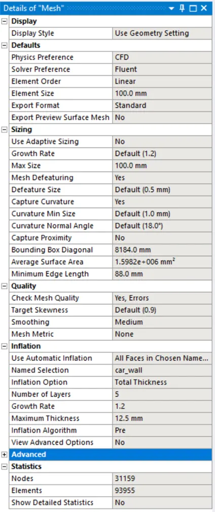
Importing the model into mesh and give the nmaes to the model and assign the multi zones using insert option and generate mesh for outer enclosure using the length of 100mm and for inner enclosure is 50mm by using body sizing and face sizing for the bottom cylindrical rod by a length of 5mm and update the mesh and assigning the infliation of total thickness 12.5 and number of layers are 5 aand make update the mesh.
Mesh:
Case1:
Outer Enclosure: 100 mm (elemental size)
Inner enclosure : 50 mm (elemental size)
Face sizing for ahmed body : 5mm (elemental size)
Inflation for ahmed body: 5layer with total thickness 12.5mm
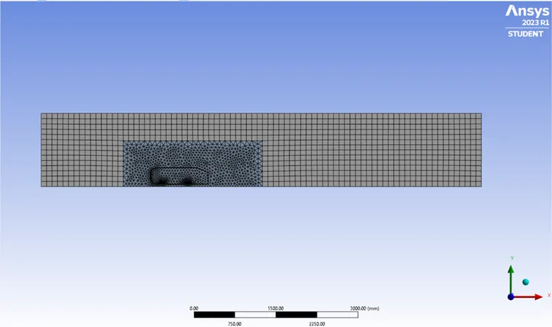
Total number of elements = 93955
Fluent Set up Procedure:
- Update the mesh before opening the fluent and mesh checking should be done.
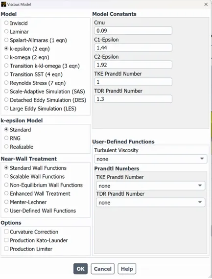
- Take the k-epsilon turbulence model because we are taking the inlet velocity 25m/s which is smaller.
- Consider the pressure density solver.
- Take 25m/s as a velocity for the inlet boundary.
- Then initialize the solution.
- After initialize we should go to the post process to create a cut plane to see the velocity profile on it.
- And create a contour plot for both pressure and velocity.
- Also, create a plot for drag and lift usinf the definition tool.
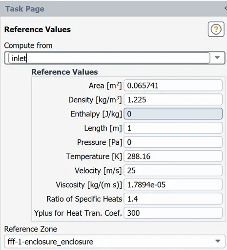
- And give the reference values for the Ahmed body.
- Run the simulation for 500 iterations.
Results:
- We should insert the plane along the z axis to get the velocity and pressure variation.
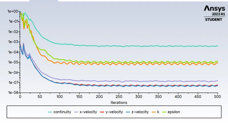
- Residual plot
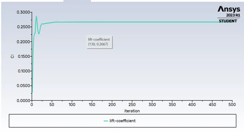
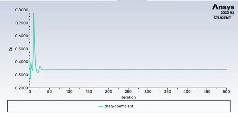
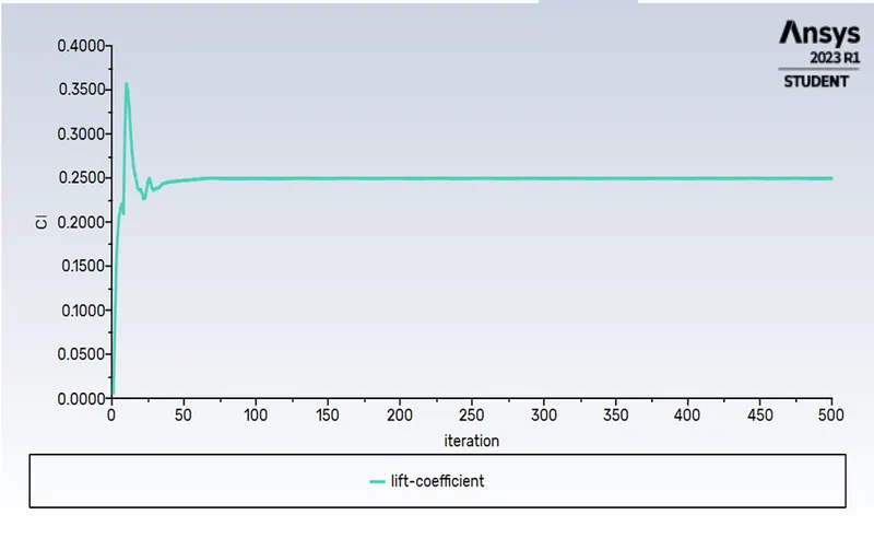
Drag and lift coefficient
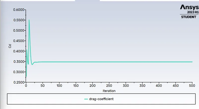
Drag coefficient:

Lift coefficient:

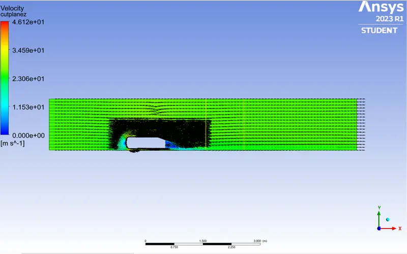
- Vector plot
4.Velocity variation
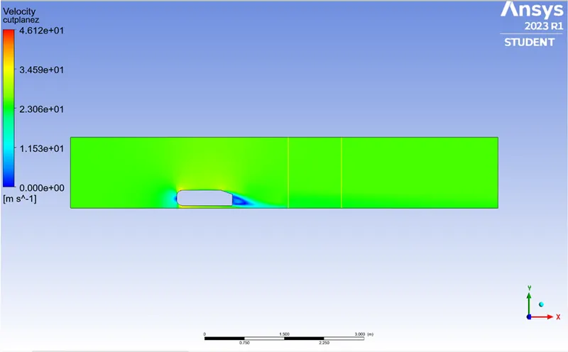
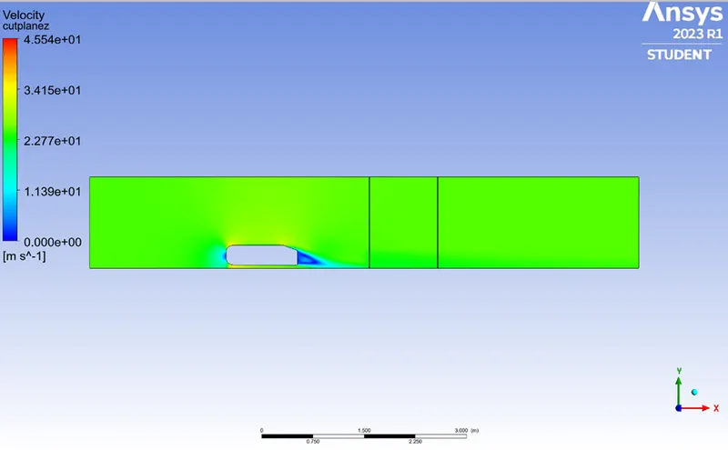
- Velocity contour plane
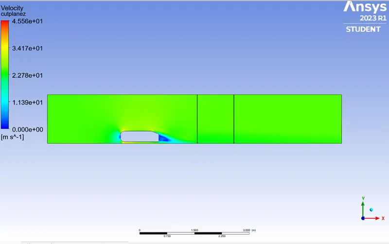
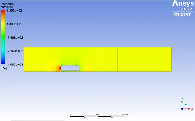
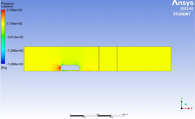
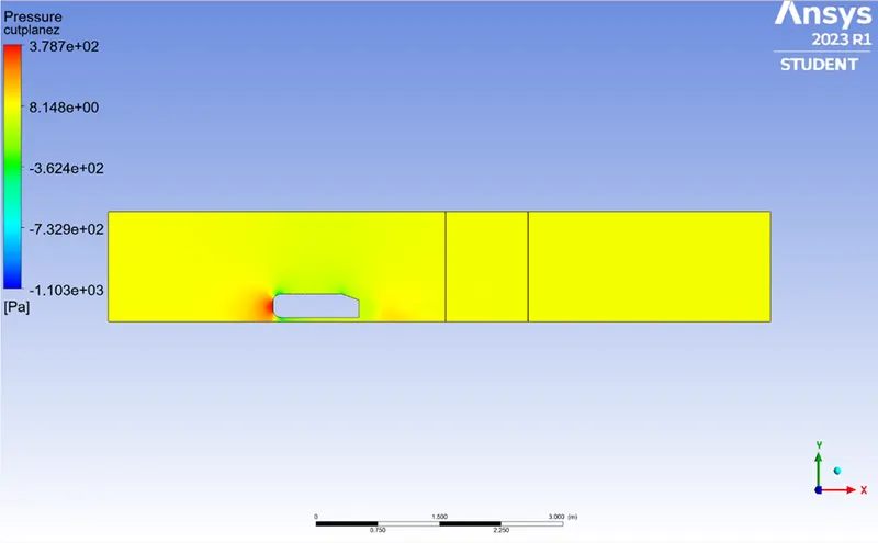
- Pressure contour plane
Mesh:
Case2:
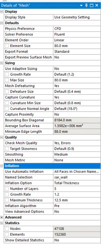
Outer Enclosure: 80 mm (elemental size)
Inner enclosure : 40 mm (elemental size)
Face sizing for ahmed body : 5mm (elemental size)
Inflation for ahmed body: 5layer with total thickness 12.5mm
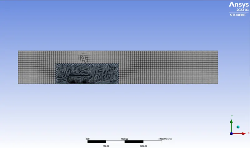
Total number of elements = 152360
- Residual plot:
2. Drag and lift coefficient
Drag coefficient:

Lift coefficient:

- Vector plot:
- Velocity contour plot:
4. Pressure contour plot:
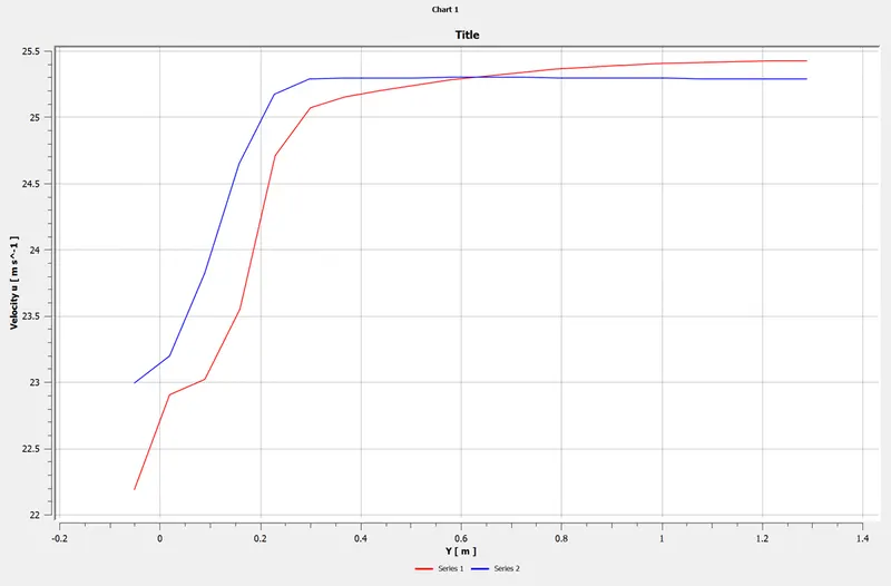
- Velocity variation
Case 3:
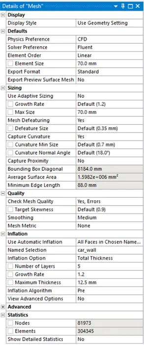
Outer Enclosure: 70 mm (elemental size)
Inner enclosure : 30 mm (elemental size)
Face sizing for ahmed body : 5mm (elemental size)
Inflation for ahmed body: 5layer with total thickness 12.5mm
Mesh:
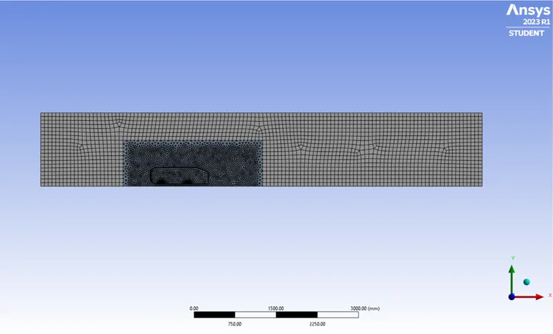
Total number of elements = 304345
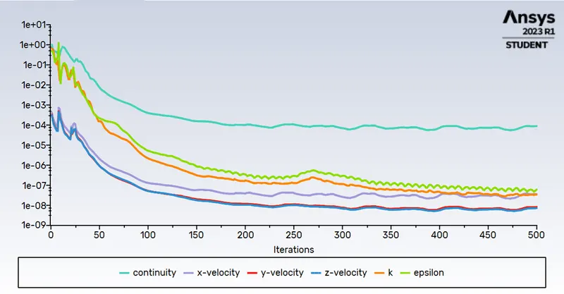
- Residual plot:
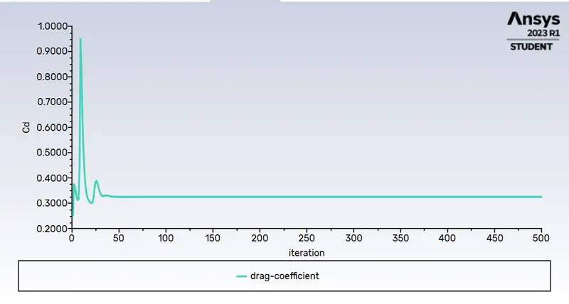
2. Drag and lift coefficient
Drag coefficient:

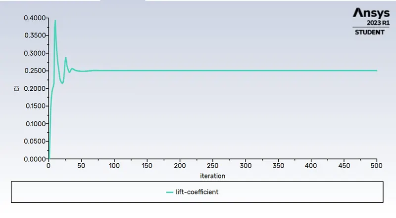
Lift coefficient:

- Velocity contour plot:
- Pressure contour plot:
5. Vector plot: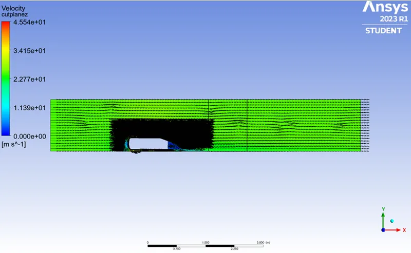
- Velocity variation:
GRID INDEPENDENCE TEST
Number of cells Cd CL
Case 1 93955 0.34818989 0.26677353
Case 2 152110 0.33973723 0.24953953
Case 3 304345 0.31986984 0.25204128
From thr above table with the refinement of the mesh drag coefficient approaches closer to the analytical values that are because more cells are assigned at the boundry layer which results in more accurate results of drag coefficients.
Conclusion:
- High pressure is formed at the frontal area of the ahmed body due to the loss of kinetic energy of the air.
- The advance pressure gradient is created near the wake regions because of the flow separation which is occurring because of the geomentry of the model. As a result flow separation alters the pressure gradient which in turn affects the drag and lift coefficients.
- In order to reduce the size of the wake region, detachement of the fluid should be fartheraway from the body which can be achieved by an increase in the slant angle.
- With the increase in mesh size, the numerical results approach closer to experimental results.