Week 3 - External flow simulation over an Ahmed body.
GIVEN
Simulate an external flow analysis of an Ahmed body using a wind tunnel velocity has 25 m/s and give the following results
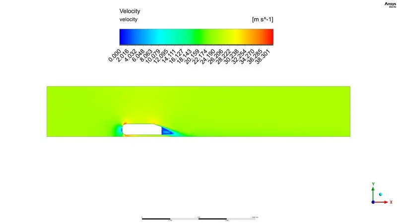
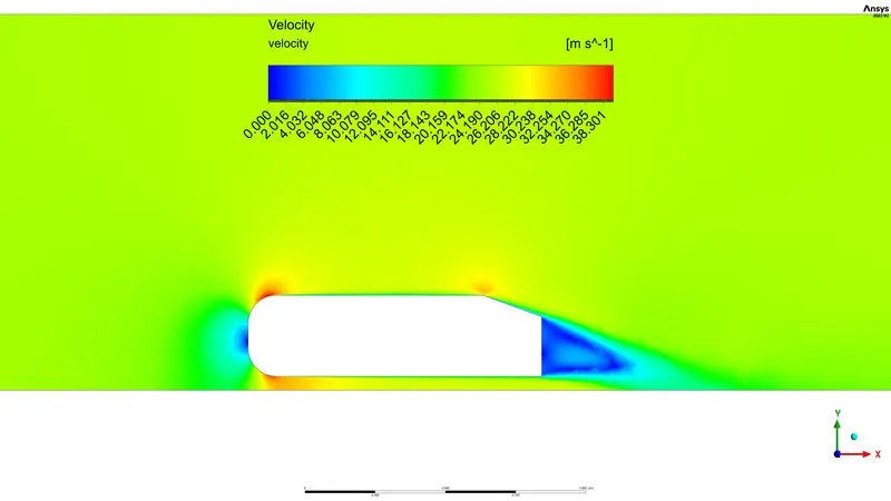
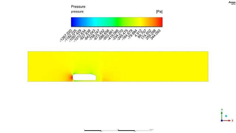
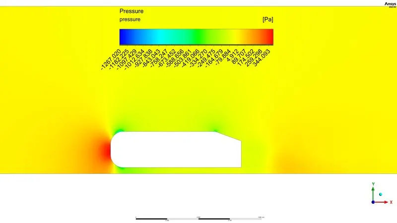
1. Velocity and pressure contours.
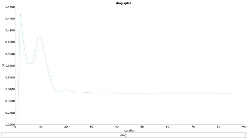
2. The drag coefficient plot for a refined case. ( For a velocity of 25m/sec, the drag coefficient should be around 0.33).
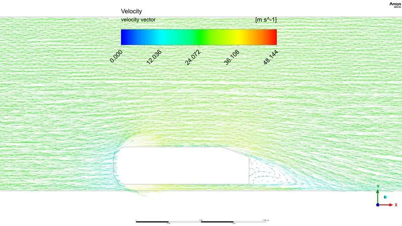
3. The vector plot clearly shows the wake region.
4. Perform the grid independency test and provide the values of drag and lift with each case.
Ahmed's body
The Ahmed body is a generic car body (a simplified vehicle model). The airflow around the Ahmed body captures the essential flow features around an automobile. namely: flow pattern and displacement around the nose, relatively uniform flow around the middle and flow separation and wake generation at the rear. This model is also used to describe the turbulent flow field around a car-like geometry. Once the numerical model is validated, it is used to design new models of the car.
The Ahmed body is easy to model, it can be effortlessly utilized for researching various properties like turbulence, drag coefficient, wake region, lift forces, and velocity magnitude at various regions of the car.
STEPS TO BE FOLLOWED
Step 1: Initially, start with importing the geometry to the Ansys workbench and prepare the geometry to do mesh
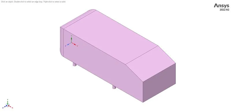
As the body is perfectly symmetric, we can simulate by considering only half body so cut the model into two halves using the split body option in the space claim.
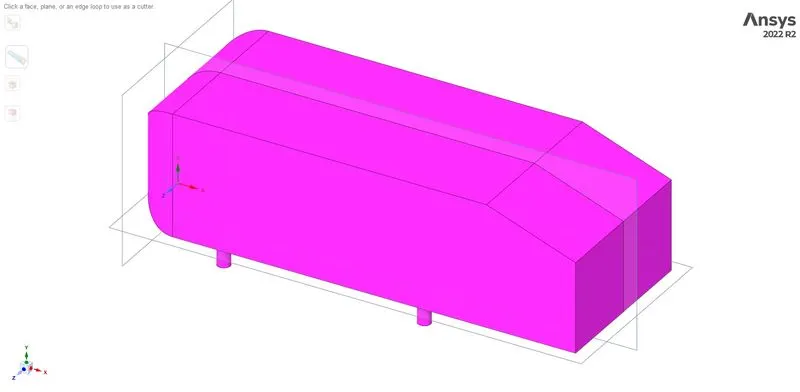
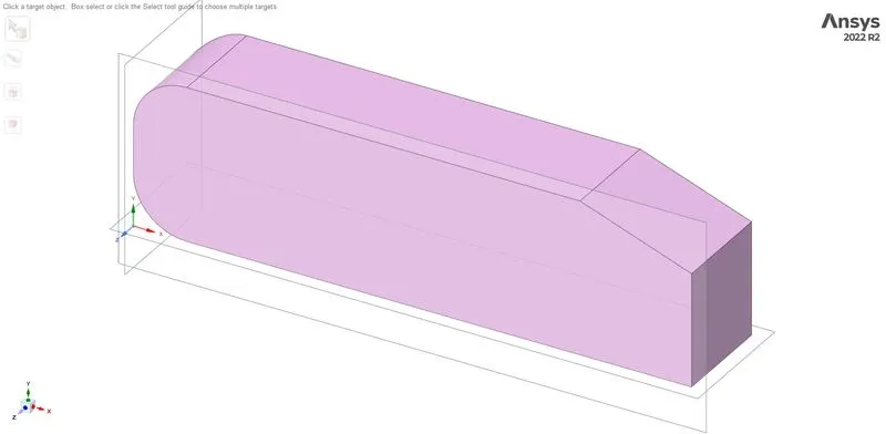
create an enclosure with the following dimensions
- From the front, it will be 2m
- From the back, it will be 5m
- From the Top, it will be 1 m
- The bottom face of the encloser is attached to the bottom
- On one side, it will be 0.5 m and another side symmetry so it will be attached to the side
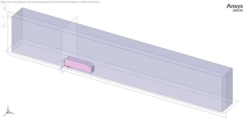
Create another enclosure with half the dimension of the previously created the enclosure
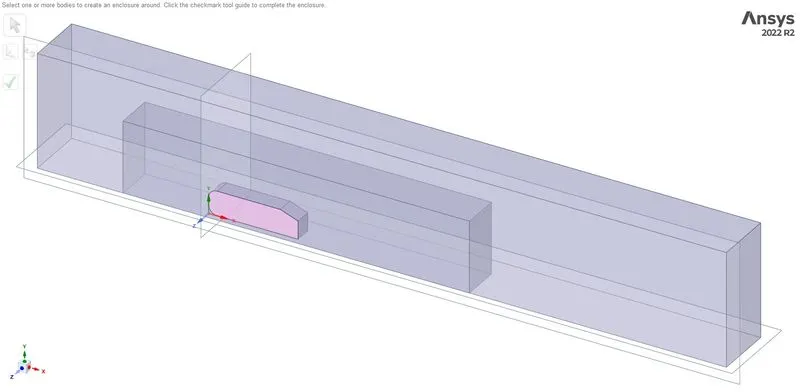
Use the interference option to remove overlapping surfaces and share topology to make it share information between the boundaries.
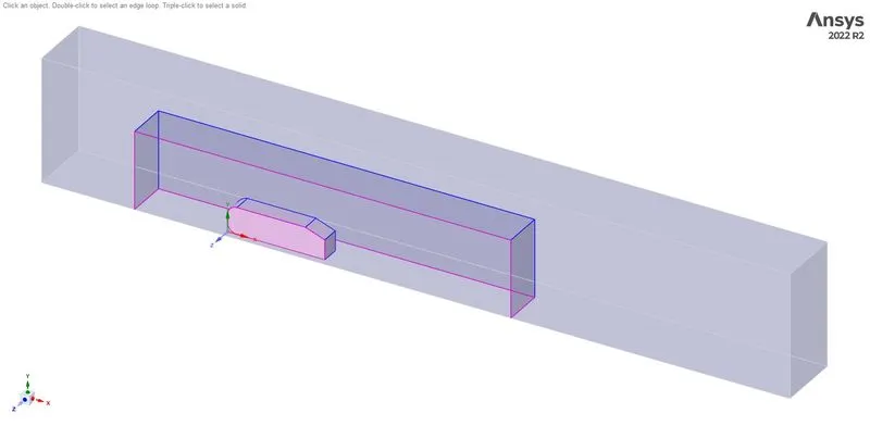
Step 2: From the space claim model create a coarse mesh to initiate the grid-independent study and note the results and refine the mesh again and note the results and so on.
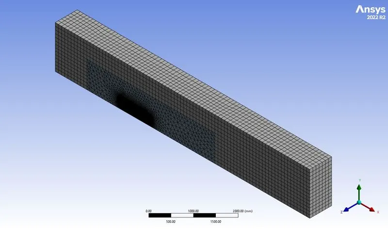
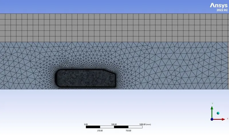
[Hear I used three different mesh coarse, medium and refined all three are shown below]
Coarse mesh
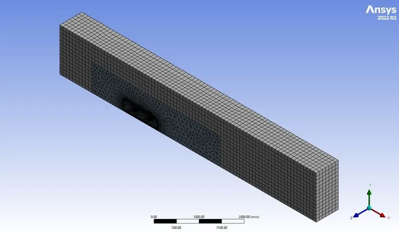
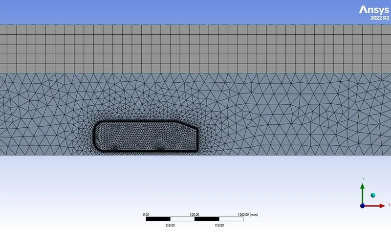
Medium mesh
Fine mesh
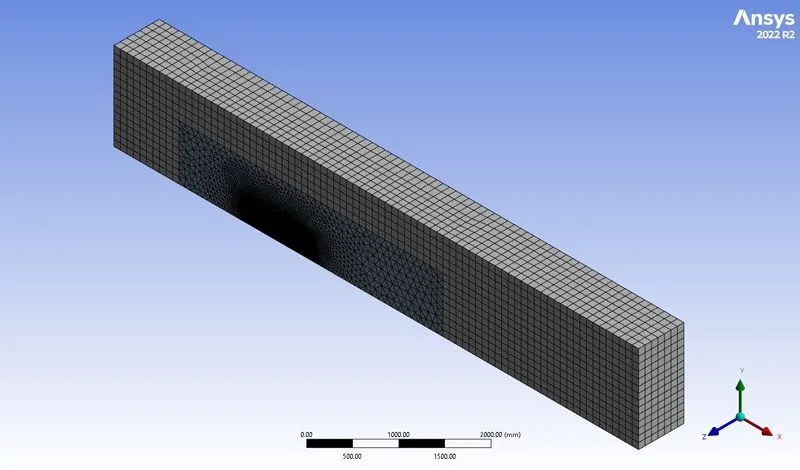
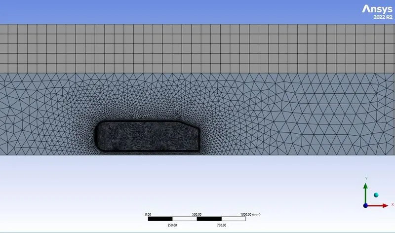
After generating the mesh, the number of nodes and elements is investigated using the statistics option. Then the mesh quality is checked by choosing the mesh matrices option in the quality section.
Step 3:In this step, the meshed geometric file has been imported to the fluent module and set the following conditions as follows in the fluent in solving the problem.
|
SOLVER TYPE |
Pressure based |
|
VELOCITY FORMULATION |
Absolute |
|
TIME |
Steady |
|
VISCOUS MODEL |
k-Epsilon standard wall function |
|
MATERIAL |
|
|
BOUNDARIES (depends on the momentum ratio) |
Inlet_x (velocity inlet)=25 m/s Outlet (pressure outlet) Gauge pressure – 0 pa Walls – stationary walls |
|
Report definition |
1. Force report drag coeff 2. Force report lift coeff |
the hybrid scheme is used for the initialization
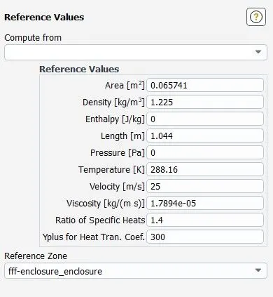
Reference Values
The most important values here are Area and Length.
Results
Note: All plots, contours and vectors were obtained from the finer mesh, due to its higher solution clarity.
Velocity contours
Pressure contour
Vector plot
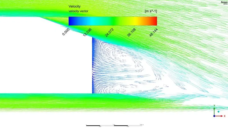
Point of Separation
Due to the slant in the rear of the vehicle, flow separation and counter-rotating vortices are generated at the slant edges.
Negative pressure at the Wake region
The flow behind an object separates from the surface and creates a highly turbulent region behind the object, called the wake. The pressure inside the wake region remains low as the flow separates and a net pressure force (pressure drag) is produced. In other words, due to the production of pressure drag being produced from flow separation, the pressure in the wake region is low
Results for grid independent study
This test will involve 3 different simulations - one where the mesh is coarse, the second one is medium and the final one is fine the results are shown bellow
Coarse mesh
Total mesh elements = 140789
Drag
LIft
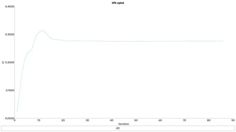
Medium mesh
Total mesh elements = 381933
Drag
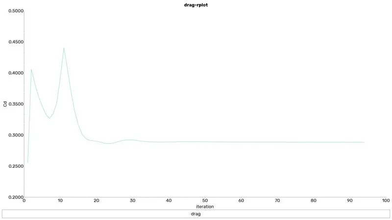
Lift
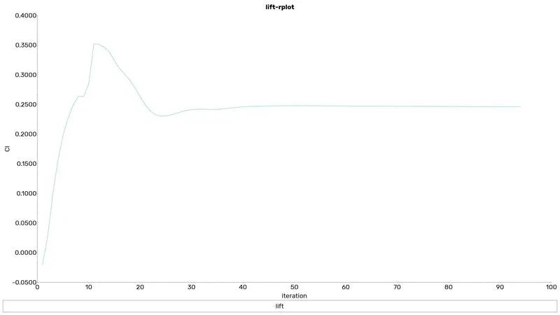
Fine mesh
Total mesh elements = 492427
Drag
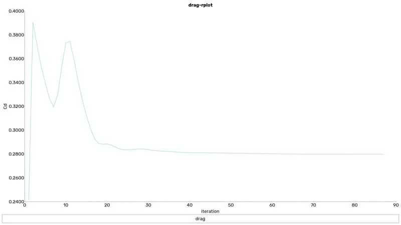
Lift
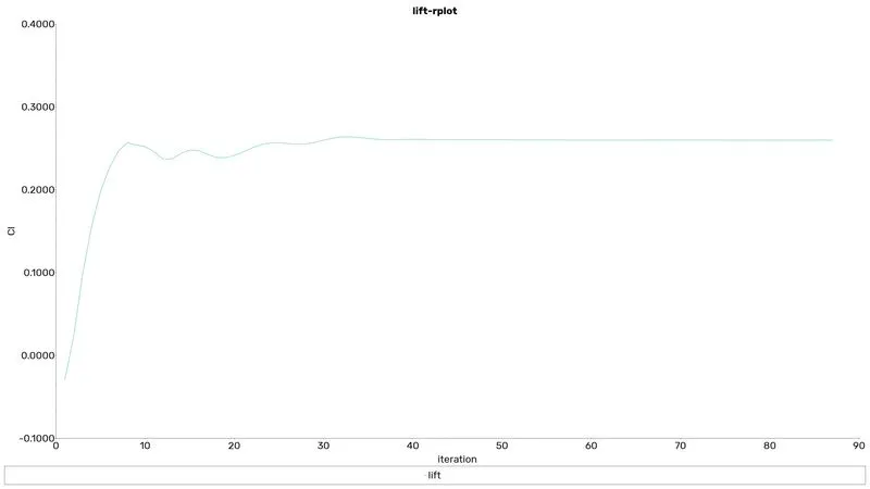
Solution discussion
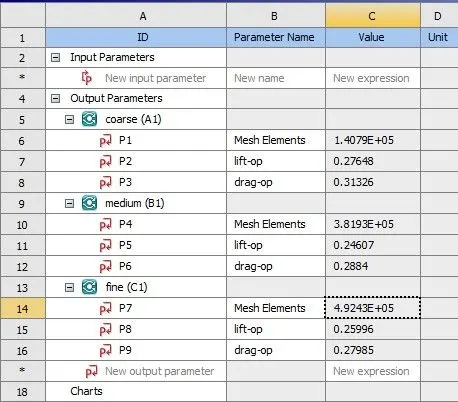
| Mesh | No mesh elements | Drag | Lift |
| Coarse | 140789 | 0.31325847 | 0.27648235 |
| Medium | 381933 | 0.28840043 | 0.24606771 |
| Fine | 492427 | 0.27985123 | 0.2599641 |
The drag coefficient decreases as the number of elements increases, The important is that the drag coefficient does not vary significantly when the mesh is made finer. While the drag coefficient varies when the mesh is made more coarse
conclusion
- The grid independency test has been conducted and reached experimental data by refining the mesh size with y+.
- All the contours shown are taken from the fine mesh because the coarse mesh did not show the wake region very well
- The wake region was created due to the movement of air and Two rotating regions can be spotted behind Ahmed's body
- By comparing the grid independently it will be clear that a significant level of refine meant is enough to reach the appropriate solution