Week 3 - External flow simulation over an Ahmed body.
Objective: Simulate the flow over Ahmed Body.
Theory:
What is Ahmed Body?
Ahmed body is a basic theoretical model used to study flow over automobiles. By studying the flow over ahmed body one can get the drag and other flow characteristics for various Reynolds numbers.
This body has been tested experimentally and wide range of data is available. Therefore by doing numerical simulation on this body one can compare it with experimental results. For any new development of vehicle the CFD is to be done, so to validate whether the CFD codes generate proper or realistic results Ahmed body is used. By comparing the data from experiments one can validate the code.
Importance of Ahmed Body
The ahmed body can be considered as a bluff body moving in close vicinity with ground.The main region where flow needs to be studied is the flow happening in the rear end of the body where flow separation occurs.
The flow separation takes place due to adverse pressure gradients. As the flow traverses along the body it happens from high pressure to low pressure, so when fluid comes to the rear of the there is flow separation because of the geometry of the body. At this point the wake region is created and hence adverse pressure gradient is faced by the fluid, so the fluid needs to travel from low pressure to high pressure and in that process the fluid recirculates and high drag is produced. To avoid this the rear of the automobile is so designed that flow remains attached to the body as long as possible without creating any separation.
Procedure:
- Import the geometry in space claim. The geometry and its dimension are given below.
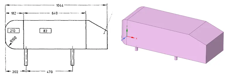
- After the geometry is opened in the spaceclaim. It needs to be prepared for the simulation. This is an external flow simulation problem. So an enclosure needs to be created so that it can depict the wind tunnel. The dimensions of the enclosure are made such that the effect of boundary layer separation is not felt away from the body,also the effect of boundary created near the wall is not felt on the body.
- The enclosure is created by giving the dimensions as follows,For the left face the distance between front end of body and left face is 2m and for right face the distance between rear face and right face of body is 5m.Bottom wall is at 0 m distance and matches with pillar end whereas top wall is at a distance of 1m from top surface of the body.
- This is the outer enclosure through which flow will happen. Now to capture the flow separation and wake region we need to look more closely in this area,so at first we will make the default mesh and run the test case to just get a rough idea about the region of flow separation and wake.
- Hence smaller enclosure is to be created near the body , the dimension are ;right face is located at a distance of 1m from the rear end of the body,left face is located at a distance of 2m from the front end of the body and top face is located at a distance of 0.5m from top of ahmed body.
- After this the geometry features of outer and inner enclosure needs to be share so share topology options is used.
Now when we generate the mesh we see that the mesh of outer enclosure and inner enclosure gets overlapped, therefore interference needs to be removed by using interference command.Also the body is symmetric about XY plane, so we can delete the other half of the body.By using this symmetry condition the simulation becomes easier and number of cells are also less.
Mesh:
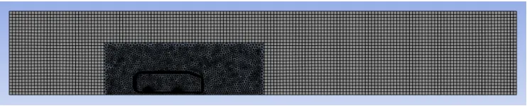
The method used for meshing is MultiZone and its hexa dominant as the enclosure geometry is properly structured. The element size is 50mm and the number of elements are 3,58,705. Now body sizing is used for inner enclosure with element size of 30mm to make the mesh more fine so that effects of boundary layer separation and wake region are captured.
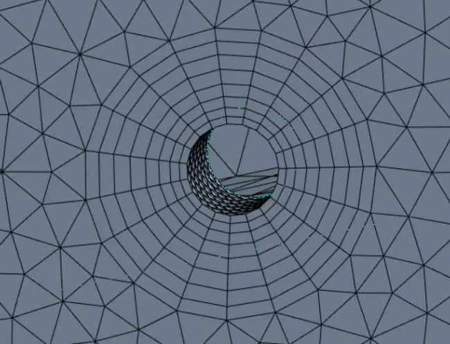
Now near the pillars edge sizing is used because the shape of the circle is like polygon ,to get it correct this sizing is used.
Number of cells:
Setup and post processing
Now near the wall we will see the boundary layer separation and wake region, so to capture this flow feature k-w model is used in fluent. The material used for this simulation is air which is by default used in ansys.After this boundary condition needs to be specified, so for this problem the inlet velocity is 25 m/s.
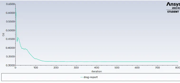
Now we need to plot or get the value of Cd for this flow, so a force report is made for this purpose. Here we need to make sure that the direction of drag force is in line with our coordinate system.
After this initialization is done so ,then the contours are plotted for velocity on XY PLANE.
After this start the calculation for 800 iterations. The convergence criteria is set for 1e-6 for continuity.
Velocity Contour:
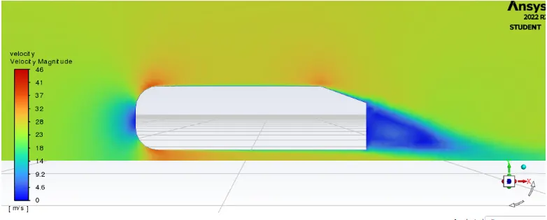
As expected we can see that flow separation behind the ahmed body.
Conclusion:
The flow separation happens at the end of the Ahmed body due to the geometry of the body. This flow separation contributes to the drag force. To reduce the drag the flow should be attached to the body ,then only separation will be avoided. From Ahmed body the designer gets first level understanding of various flow separation points and this can be extended or used for further analysis.