Week 3 - External flow simulation over an Ahmed body.
Title: External flow simulation over an Ahmed body.
Aim: To simulate flow over a Ahmed body to
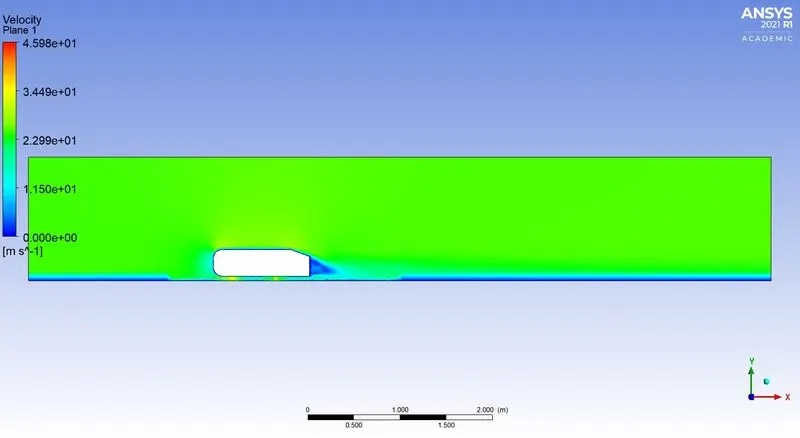
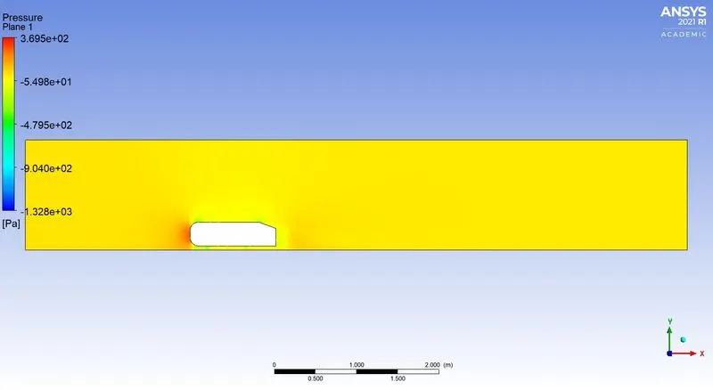
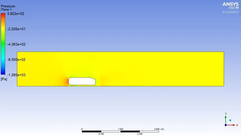
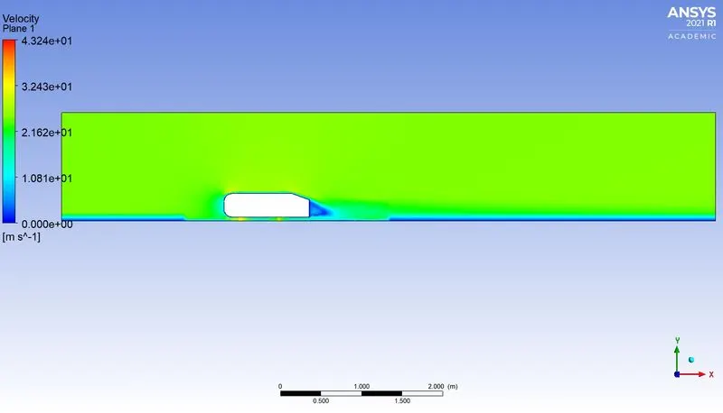
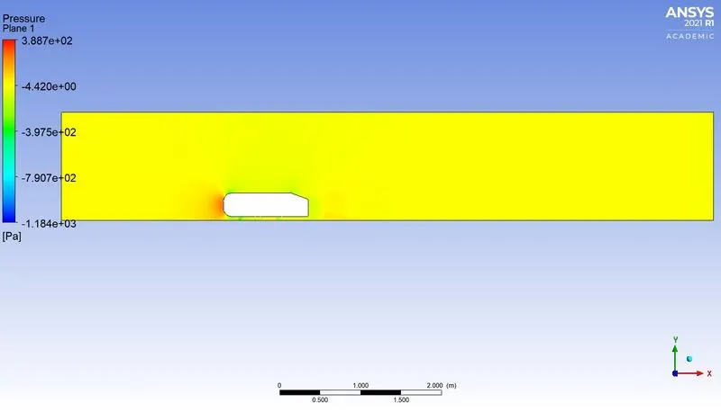
- Get Velocity and pressure contours.
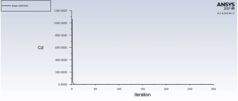
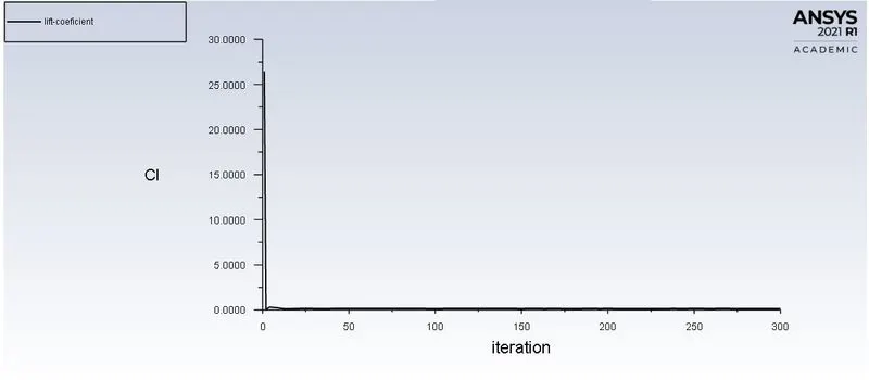
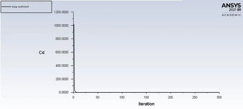
- Find out the drag coefficient plot for a refined case.
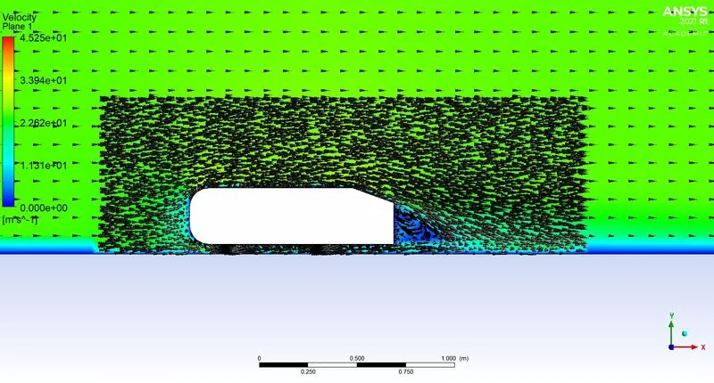
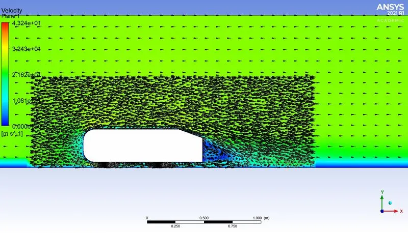
- Plot the the velocity vectors clearly showing the wake region.
- Perform the grid independency test and provide the values of drag and lift with each case.
Theory:
Ahmed body is a simplified model of vehicle. It is used to capture essential flow features around a automobile, experimentally and numerically. Although this model is very simple, but it allows to get essential features of flow around a automobile. This model is also used to validate the CFD software by comparing the results obyained by CFD software with the experimental results.
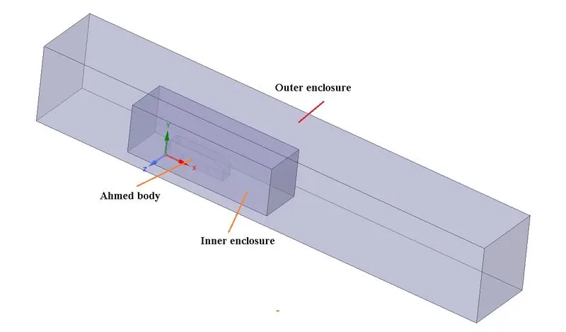
Following Ahmed body model is used for the simulation
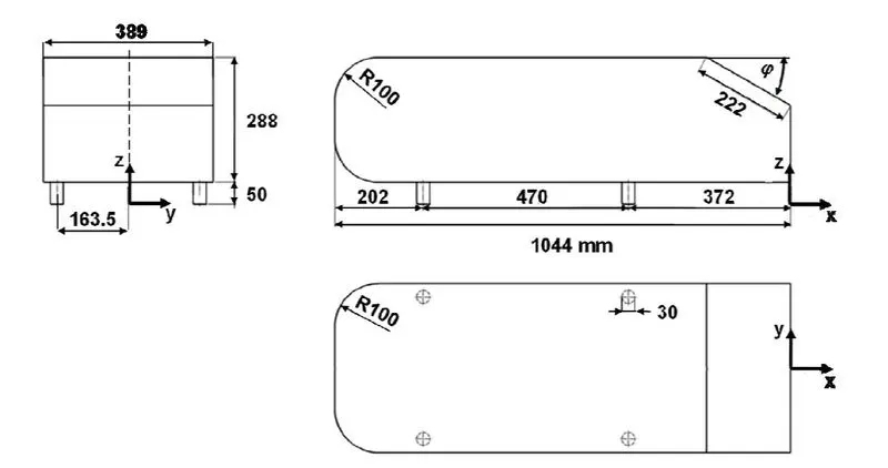
Figure: Model of Ahmed body used for simulation
Simulation with basic mesh
- Spaceclaim model of Amhed body
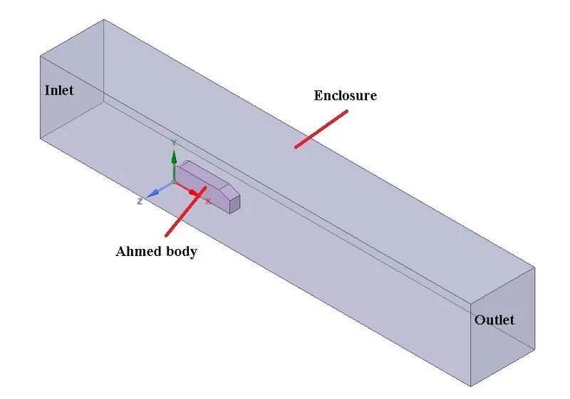
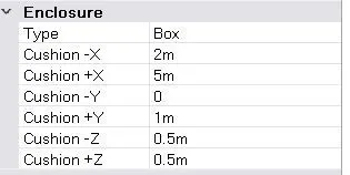
- Size/dimentions of enclosure
- Meshing of a model
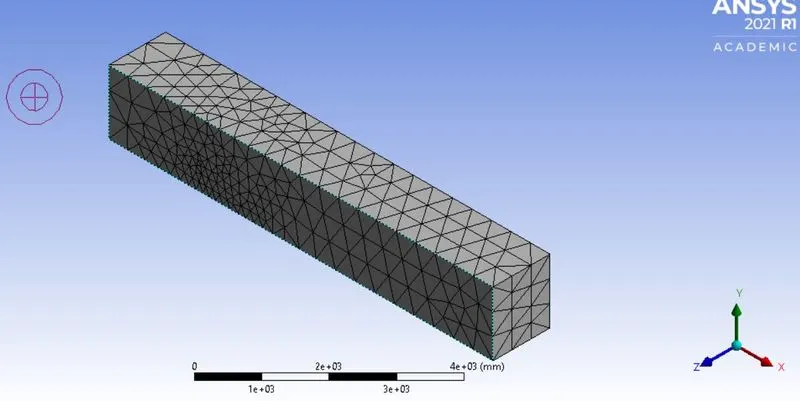
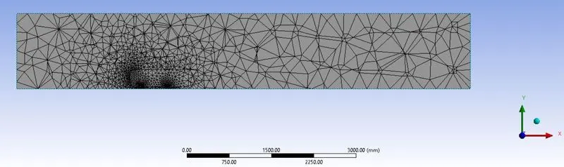
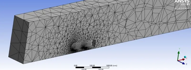
Total no. of nodes = 16576
Total elements = 83933
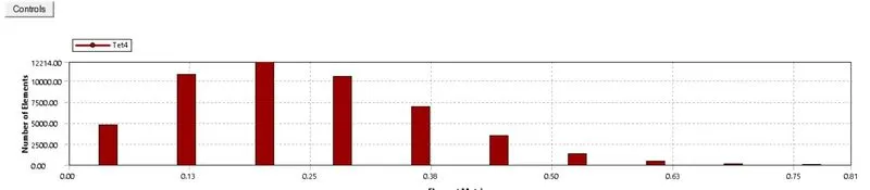
Simulation settings in Ansys Fluent
Pressure base solver is used and steady state simulation is carried out
Following boundary conditions (BC'c) are provided
1) At inlet:Velocity inlet
2) At outlet: Pressure outlet
3) On car model: No slip BC
4) For remaining four walls of enclosure symmetry BC is provided
Fluid used is air with default properites
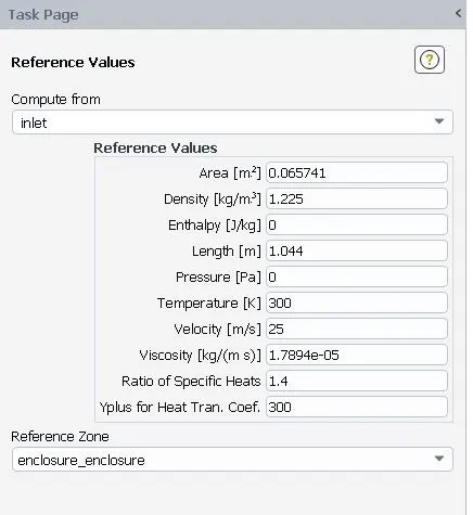
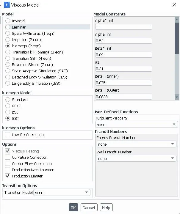
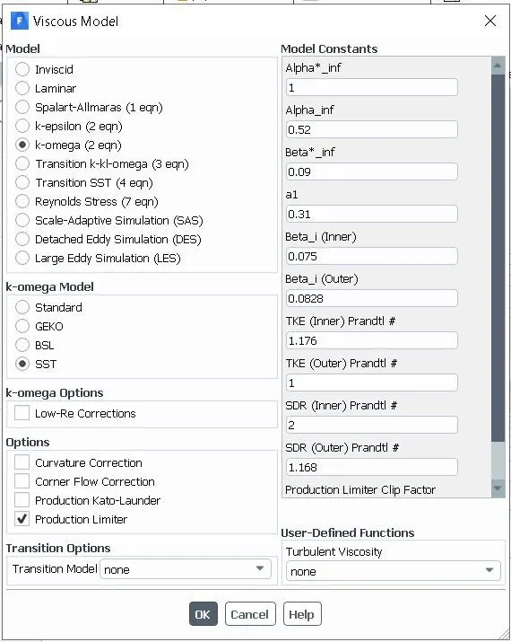
K-omega turbulance model is used with SST wall function
Results
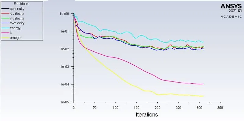
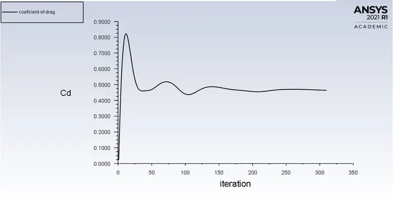
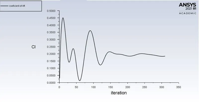
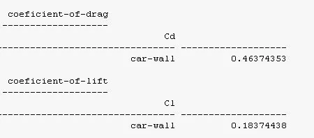
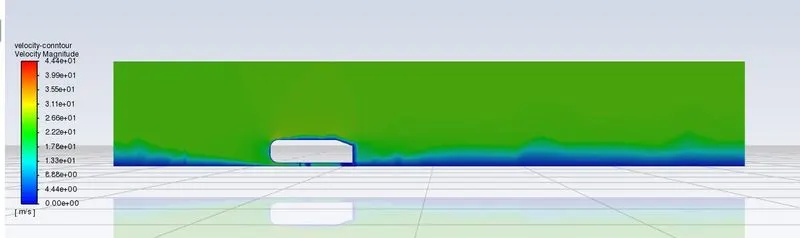
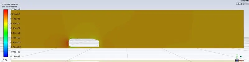
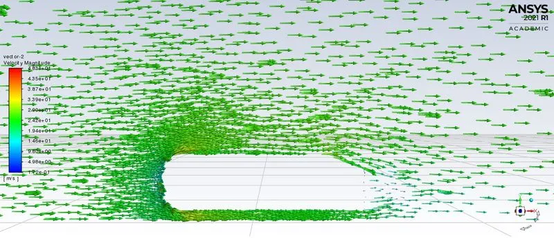
By using k-epsilon turbulance model with standard wall function, follwing values are obtained for Coeficient of drag (Cd) and Coeficient of lift (Cl)
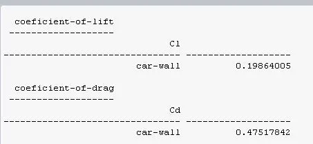
So there is very little varition in value of Cd and Cl
Experimental value of drag coeficient (Cd) for Ahmed body under consideration at a velocity of 25 m/sec is 0.33. But from above simulation Cd is coming out to be 0.47. Hence to get accurate value of Cd, model and mesh is modified as follows.
Another enclosure is created around a Ahmed body as shown in below.
Mesh
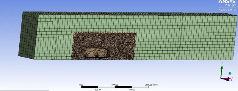
Simulation is carried out for follwing 3 cases
| Case No | Element size for outer enclouser (mm) | Element size for Inner enclouser (mm) | Total elements |
| 1 | 100 | 35 | 294531 |
| 2 | 100 | 34 | 317574 |
| 3 | 100 | 33 | 342031 |
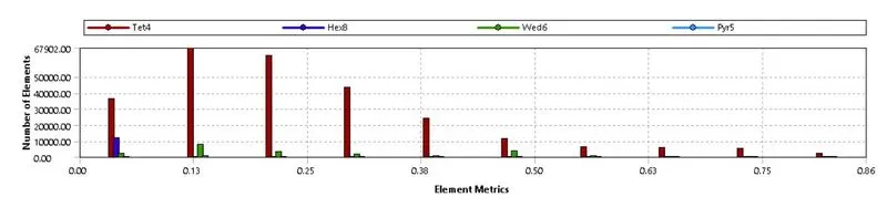
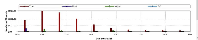
Mesh quality
Case 1
Case 2
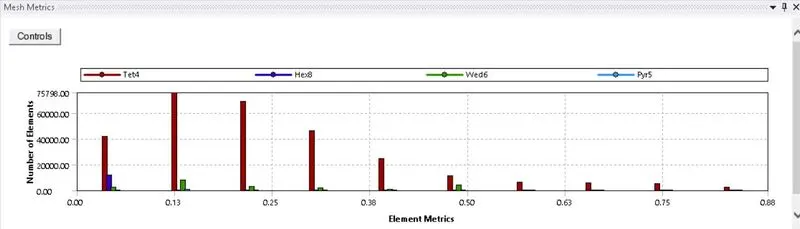
Case 3
Simulation settings
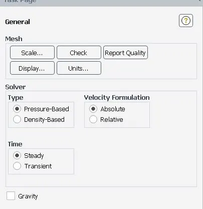
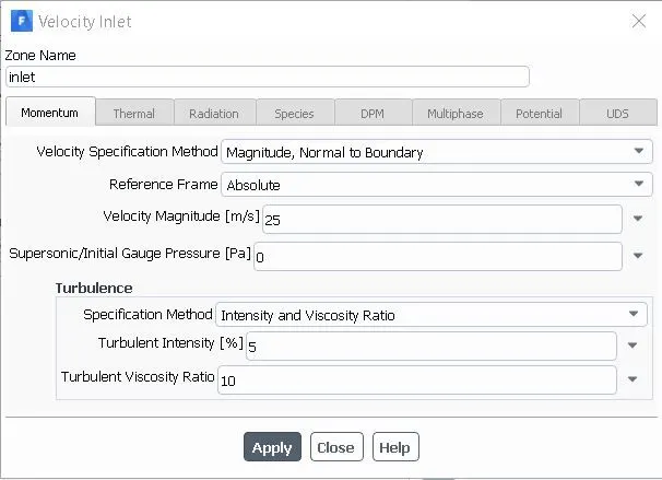
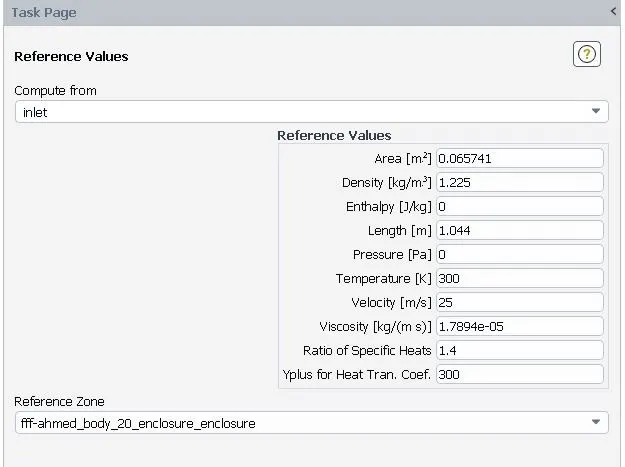
For all 3 cases Pressure based solver is used, simulation is carried out at steady state and simulation is carried out at 25 m/sec.
K-omega turbulance model is used with SST wall function. For all 3 cases value of Y+ used is 0.1.
following boundary conditions are provided
1) At inlet:Velocity inlet
2) At outlet: Pressure outlet
3) On car model: No slip BC
4) Top wall two side walls of outer enclosure: Symmetry B.C.
5) Bottom wall of outer enclosure below car model: Wall BC
Results
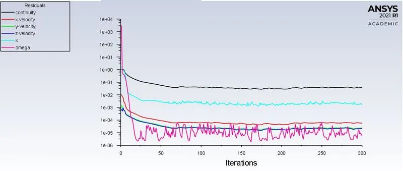
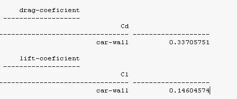
Case 1
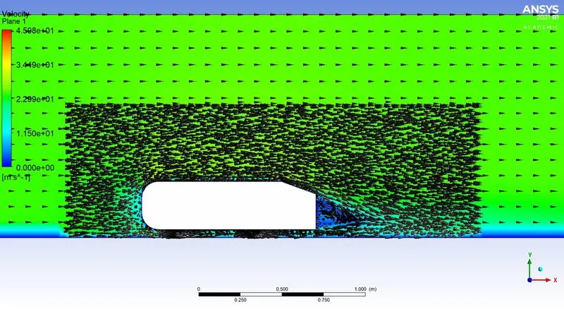
Case 2
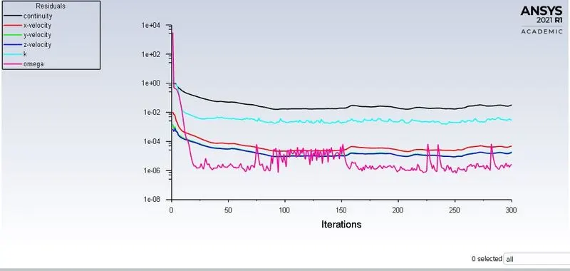
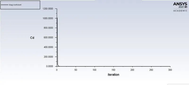
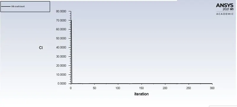
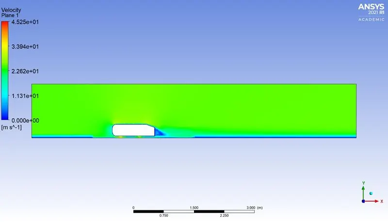
Case 3
Discussion of results and conclusion
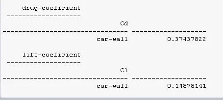
| Case No | Element size for outer enclouser (mm) | Element size for Inner enclouser (mm) | Total elements | Coeficient of drag (Cd) | Coeficient of life (Cl) | % Error in Cd |
| 1 | 100 | 35 | 294531 | 0.3370 | 0.1460 | 2.12 |
| 2 | 100 | 34 | 317574 | 0.3743 | 0.1487 | 13.42 |
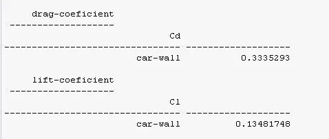
| 3 | 100 | 33 | 342031 | 0.3335 | 0.1348 | 1.06 |
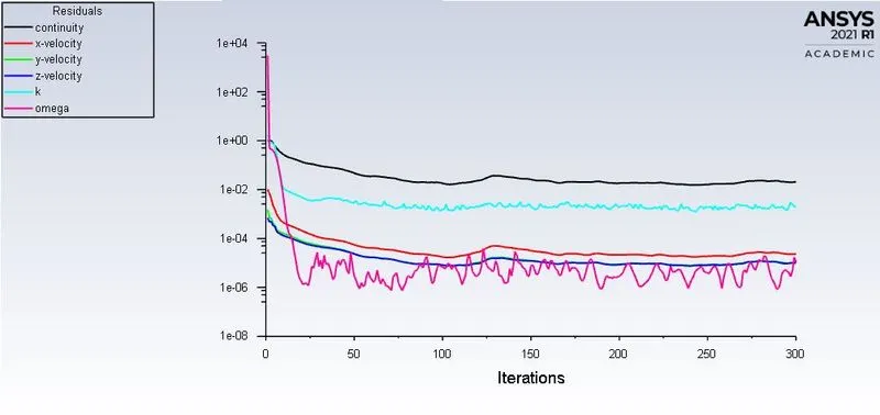
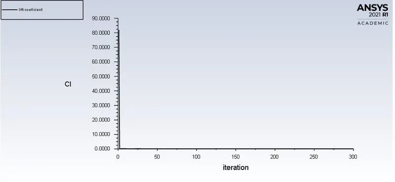
From above table it is seen that, for first and third case, accurate value of Cd is obtained. For second case we may get accurate value of Cd, of we run simulations for few more iterations.
Also from pressure contour it is seen that, at the rear end of Ahmed body, negative pressure is created because of flow saperation. This is because when, air leaves the ahmed body, there is sudden change in flow cross section area.Because of that there is a negative pressure gradient and flow saperates at the rear end from surface and there is formation of negative pressure gradient. Negative pressure gradient is not good from engineering applications perspective as it leads to flow saperation and also high drag force acts on a body due pressure difference between front and rear side of body.