Week 3 - External flow simulation over an Ahmed body.
Aim
- To define the Ahmed body and its importance.
- To Simulate flow over the Ahmed body.
- To perform the grid dependency test and post process the results
Ahmed Body and Its Importance:-
Ahmed body is a simplified car body and was first created by S.R Ahmed.This shape provides a model to study geometrical effects on the wakes of ground vehicles. This is the kind of baseline geometry for automobile bodies. The flow of air around Ahemd body captures the essential flow features around an automobile and it describes how to calculate the turbulent flow field around a simple car-loke geometry using the turbulent, flow, K-epsilon interface.
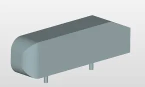
An Ahmed body represents a simplified like vehicle volume which helps understand the fundamental physics defining by the engineers the lift and drag forces and coefficients at certain characteristically velocities, pressure differences, and seeing and analyzing the vortices, turbulence and Reynolds number obtained. ANSYS is a general purpose FEA and CFD simulation software. It gives numerical prediction of the behavior of a system.
These numerical predictions need to be validated by experimental data. People working in vehicle aerodynamics use Ahmed body to validate their numerical model because the experimental data from wind tunnel testing is available for Ahmed body. Once the numerical model in validated, it is used to design new models of the car.
Its shape is simple enough to allow for accurate flow simulation but retains some important practical features relevant to automobile bodies. This model describes how to calculate the turbulent flow field around a simple car-like geometry using the Turbulent Flow, k-epsilon and k-omega interface. Later, either experimentally or computationally it can be recreated all the same but with a desired geometry, new to come up to the market or a research.
Simulate flow over the Ahmed body :-
Geometery
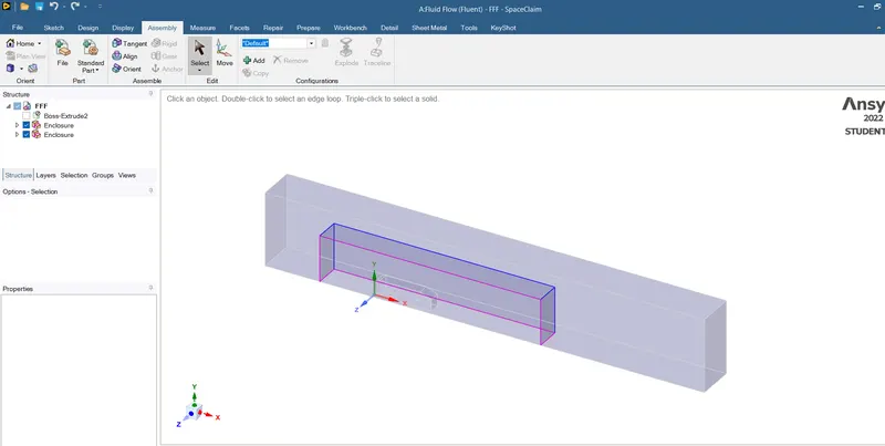
setting up geometry in the spaceclaim.
- The enclosure dimensions are 2m in front, 5m in back, 0in bottom, 1m for the top and 0.5-0.5m in both the sides.
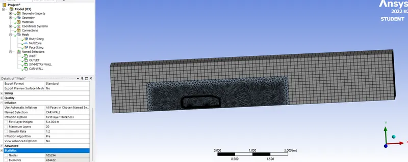
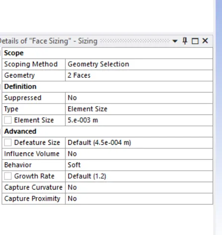
- And create one more enclosure around the body so we can provide the separate target mesh length for both the case also we will have the gradually increasing mesh size.
- The second enclosure will have the 0.5m in front, 2m in back, 0m in the bottom, 0.5m in the top and 0.25-0.25m for both the sides.
- enable interfernece.
- Use split command to delete the half symmetry part, so we will have the half mesh elements to cover.
- supress the car body.
- enable share topology.
Mesh
|
Case |
Base body |
Car body |
Face |
| Case-1 |
100 mm |
50 mm |
8 mm |
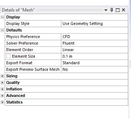
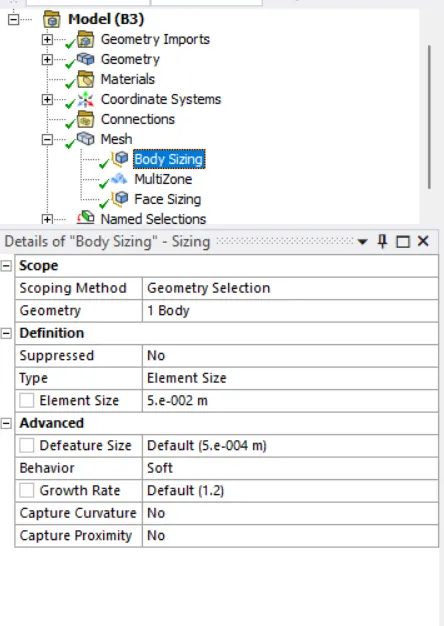
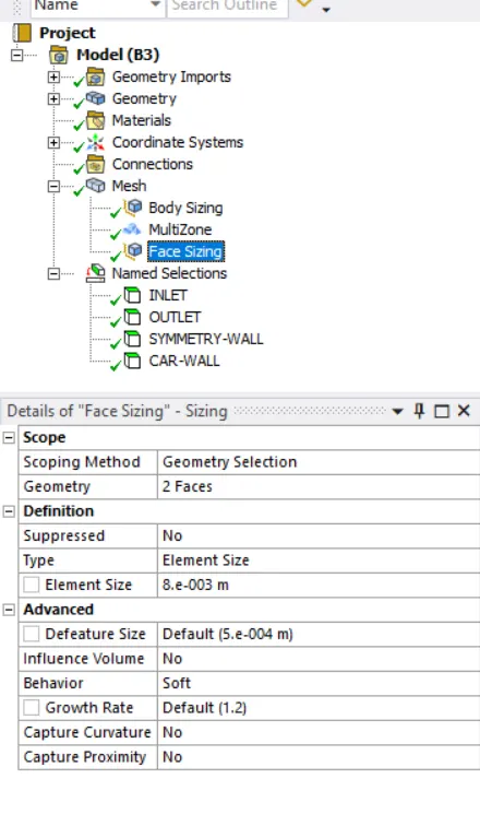
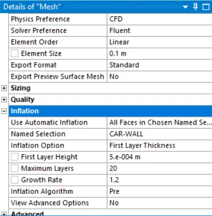
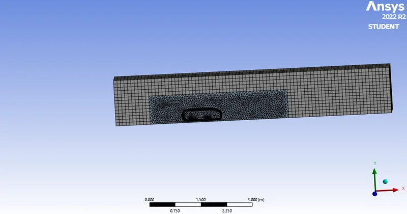
Setup
- Quality check> type> pressure based solver, steady state analysis
- Viscous model is k-omega SST.
- Material-air
- Under the boundary condition the inlet will have the velocity of 25m/s.
- The outlet will have the 0-gauge pressure.
- The wall is symmetry condition.
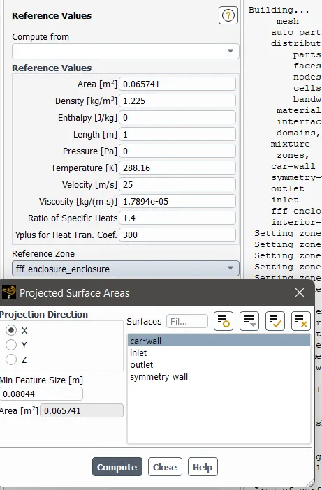
- Under the reference value we will have the front projected area and the values of material with the model length need to be updated.
- create the defination for drag and lift coffiecient
- Hybrid initialization-run for 100 iteration
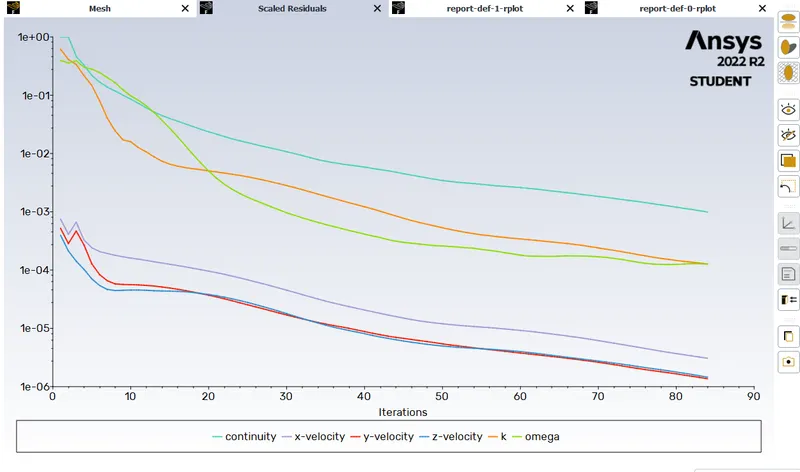
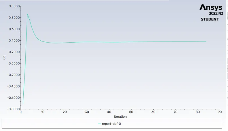
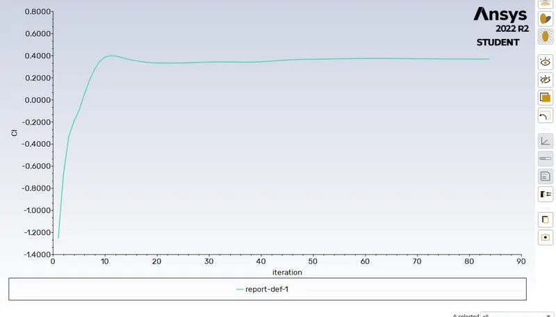
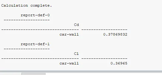
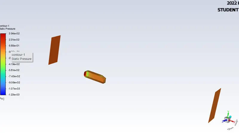
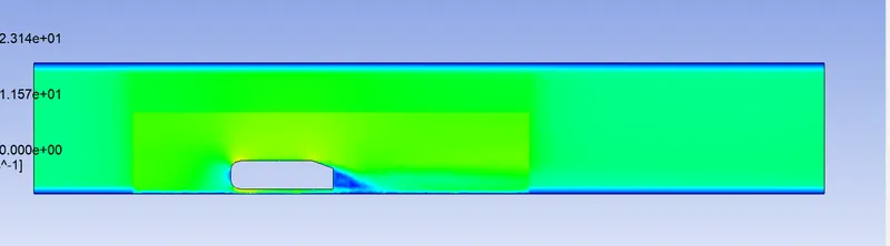
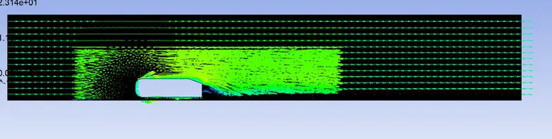
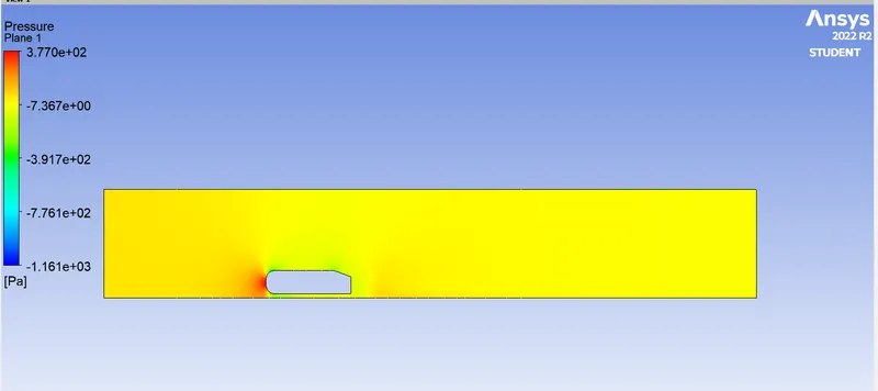
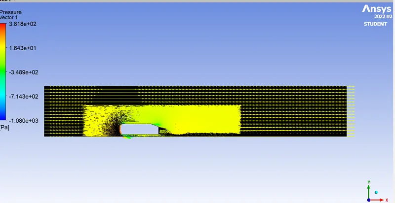
Pressure contour
Case 2
|
Case |
Base body |
Car body |
Face |
| Case-2 |
100 mm |
30 mm |
6 mm |
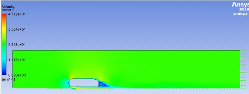
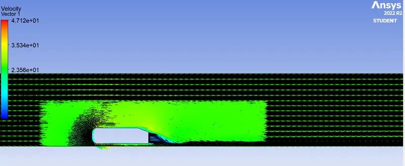
Case 3
|
Case |
Base body |
Car body |
Face |
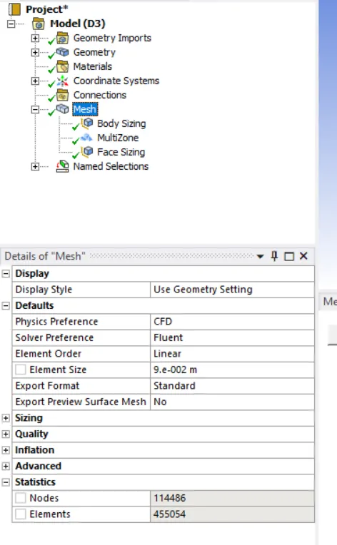
| Case-3 |
90 mm |
30 mm |
5 mm |
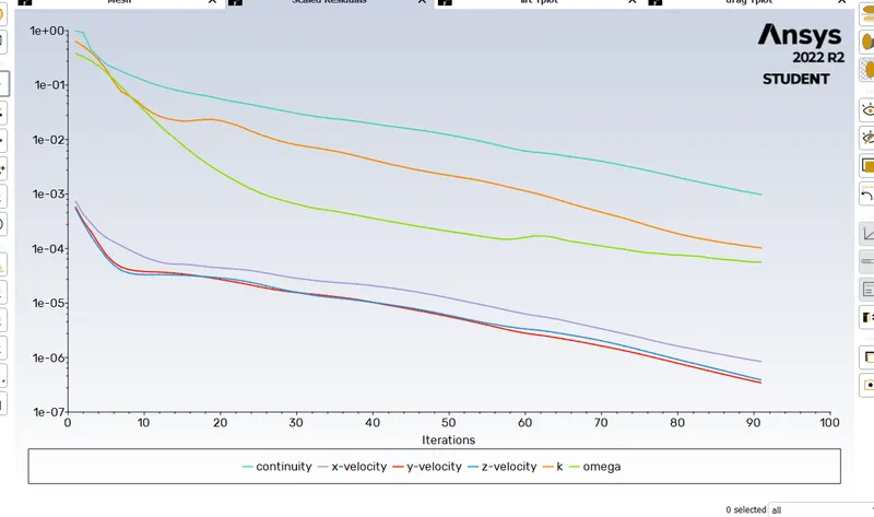
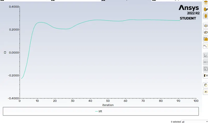
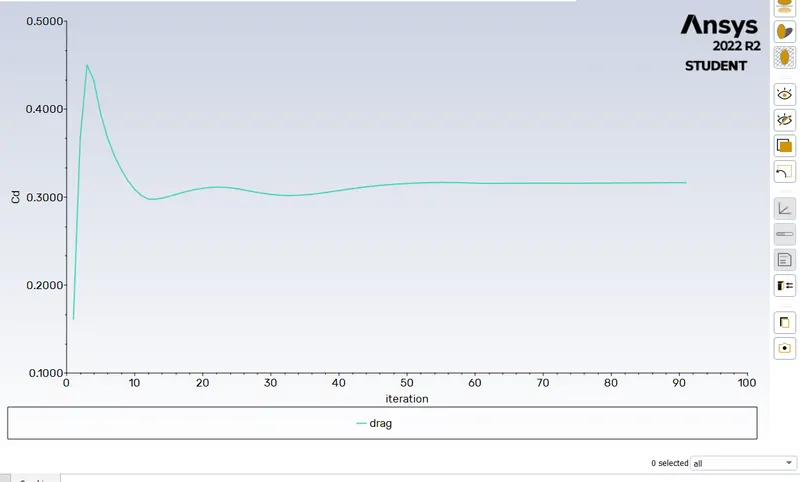
Conclusion
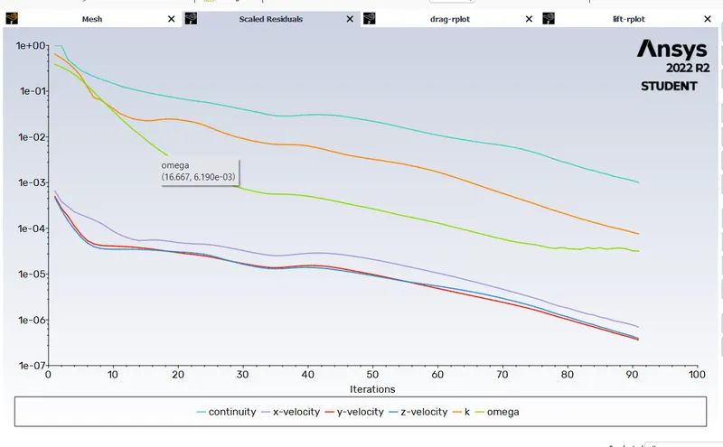
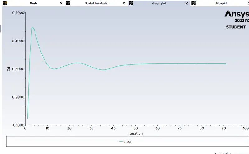
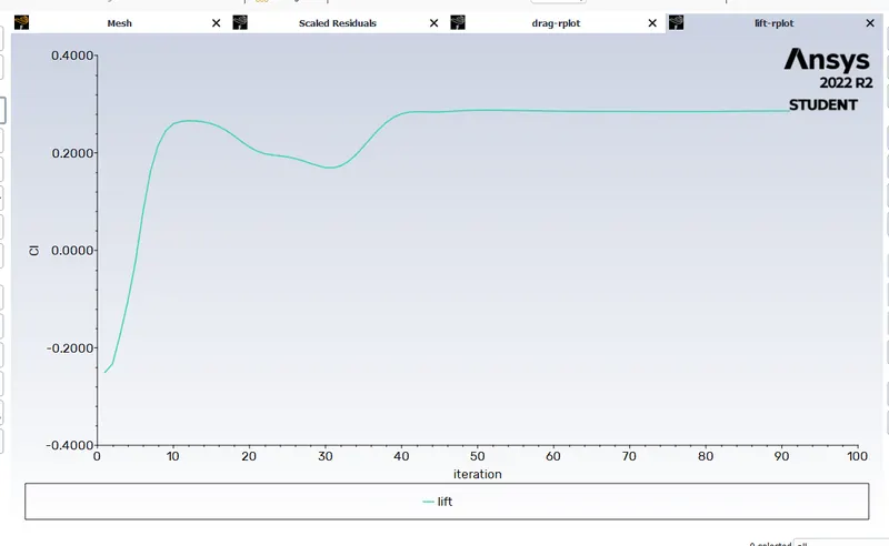
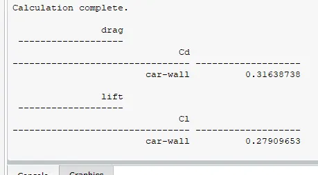
as the mesh is refined the drag and lift cofficient value decreases.
|
Case |
Base body |
Car body |
Face |
Drag Co |
Lift Co |
| Case-1 |
100 mm |
50 mm |
8 mm |
0.37869 |
0.36965 |
| Case-2 |
100 mm |
30 mm |
6 mm |
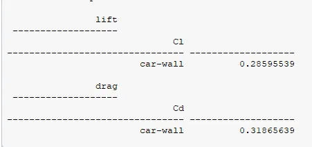
0.31865 | 0.285955 |
| Case-3 |
90 mm |
30 mm |
5 mm |
0.31638 | 0.279096 |
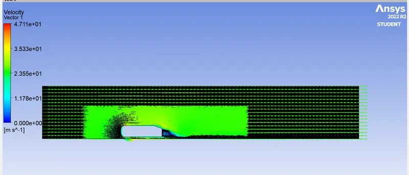
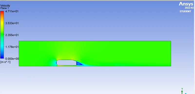
when a fluid is forced to flow over a curved surface at high velocities. A fluid follows the front portion of the curved surface with no problem, but it has difficulties remaining attached to the surface on the back side. At sufficiently high velocity, the fluid stream detaches itself from the surface of the body. This phenomenon called the flow separation.
The location of the flow separation depends upon the several factors such as the Reynolds number, the surface roughness, and the level of fluctuation in the freestream. The majorly it occurs at the Sharpe edges over the model.
And at the flow separation region downstream to the body there is vortex started to form this vortex has the separated velocity this region is further called the wake region, and The pressure inside the wake region remains low as the flow separates and a net pressure force (pressure drag) is produced
so,due to the pressure drag i.e. produced from flow separation, the pressure in the wake region is low. This is what is causing the vacuum.