Week -2
Aim - Make a Simulink model of a Doorbell using a solenoid block with the following details:
Create a situation where the switch is closed for 2 seconds and then released.
Theory
Doorbell - When the doorbell button is pressed, an electrical circuit completes that allows electricity to flow through the doorbell's internal electromagnet. The magnetic field generated by the electromagnet is then used to power a mechanism that creates the doorbell sound. Doorbells are low-voltage devices.
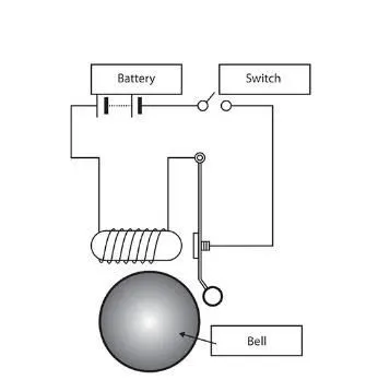
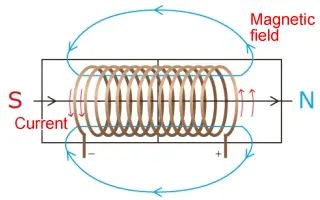
Solenoid - A solenoid is a device comprised of a coil of wire, the housing, and a moveable plunger. When an electrical current is introduced, a magnetic field forms around the coil which draws the plunger in.
Input blocks to create the model
1. Pulse Generator (supply)
2. Simulink-PS converter
3. Switch
4. Battery
5. Solenoid
6. Translational Motion sensor
7. PS terminator
8. Solver configuration
9. Electrical Reference
10. Mechanical Translational Reference
11. ps-Simulink Converter
12. Scope and Display Block
Model
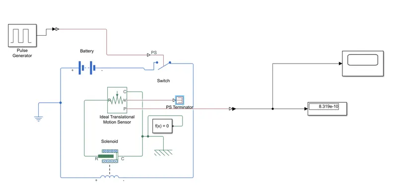
Model Explanation
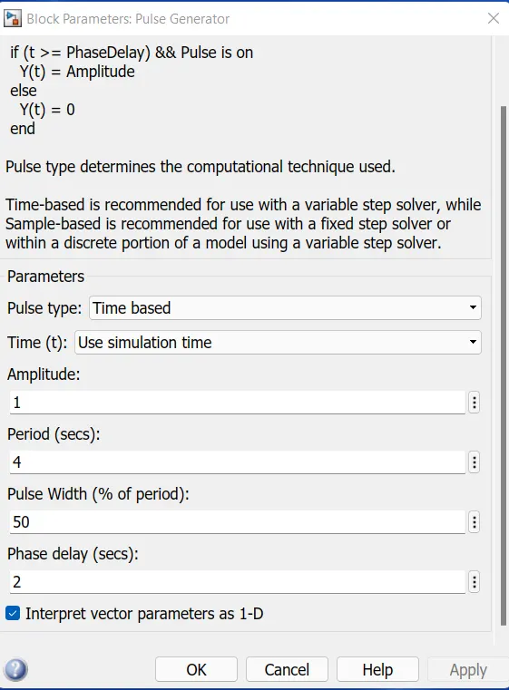
1. The pulse generator is used to give the signal input where Amplitude-1, Period 4 sec Pulse width=50% and Phase delay-2 sec
2. After that the input signal is converted into physical form with the use of Simulink-PS Converter and further sent to the switch of the electrical circuit. The electrical circuit consists of a solenoid, a battery, and a switch. An electrical reference is provided in the electrical circuit. The mechanical part of the solenoid is connected to an ideal translation motion sensor and mechanical translational reference
3. The P-part of the sensor makes a connection with the PS-Simulink Converter to provide the output in signal form. Further, the converter is connected with scope to display our output signal. and a ps terminator is also connected to the sensor.
4. A solver configuration is connected to an electrical circuit to solve all parameters before the beginning of the simulation.
Output
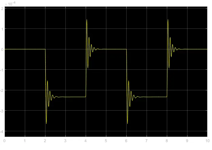
as shown in the graph, after 2 seconds bell rings. for 2 seconds amplitude is zero.
2.
Aim - Use a thermistor to sense the temperature of a heater & turn on or turn off the fan as per the below conditions:
Temperature source: 20 °C from 0 to 10 seconds, 27 °C from 10 to 30 seconds, 23 °C from 30 to 50 seconds
Fan conditions: ON if the temperature is above 25 °C, OFF otherwise.
Theory -
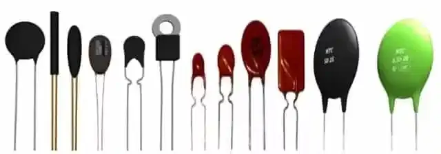
Thermistor- A thermistor is a resistance thermometer or a resistor whose resistance is dependent on temperature.
Simulink Model -
Explanation
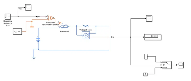
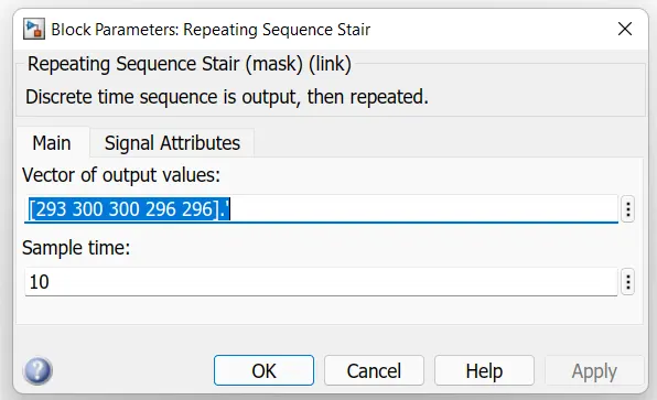
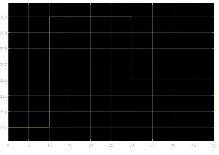
1. At first, the signal is created by using a Repeating sequence stair block and further passes to the "Simulink-PS Converter" to convert the input signal into the physical signal.
Input Wave
2. This physical signal is connected to a block "Controlled Temperature Source". This block is connected to the thermistor and a "Thermal Reference" block.
3. The thermistor is a part of an electric circuit where a battery, a voltage sensor, a resistor connected parallel to the voltage sensor, and an electrical reference are connected to make a complete circuit. A solver configuration is connected to that electrical circuit to solve all parameters before the beginning of the simulation.
4. The voltage sensor senses the temperature in the form of voltage and sends the data to its port 'V'.
5. From this port, we get our output and send it to the "PS-Simulink Converter".
6. From the converter, the signal sends the voltage data from the Voltage Sensor to the display. This display gives us the value of the voltage at 296K.
7. To determine the threshold value a constant block of 298 K is connected at input and determines the voltage by using the display block, and the value is the threshold value for the switch for the given condition.
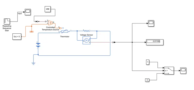
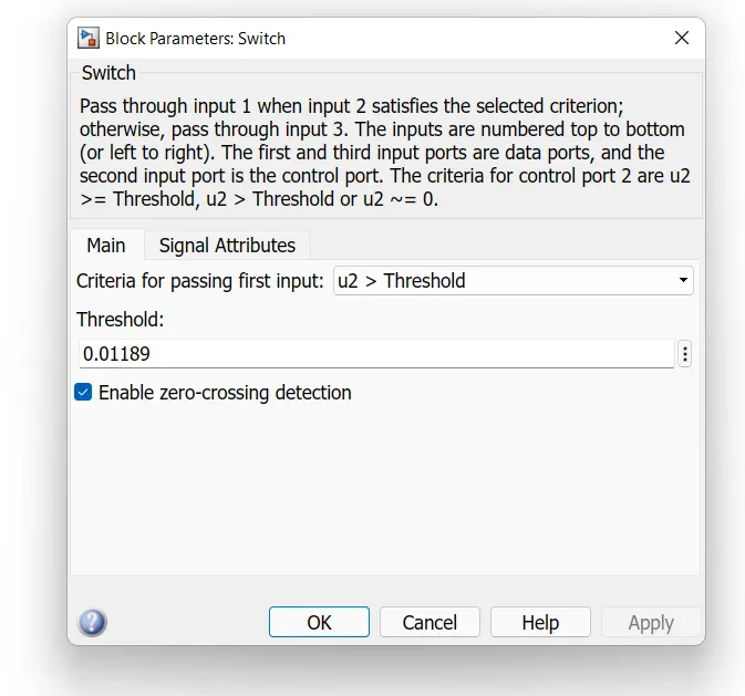
7. From the converter the signal is sent to the threshold switch. In the switch, the threshold limit is set to 0.01189. If the temperature is above or equal to the threshold limit, then it gives "1" as output which is "Switch On". If the temperature is below the threshold limit, then it will give "0" as output which means "Switch Off".
8. The switch is connected to the scope where we can see our output plot.
Output:
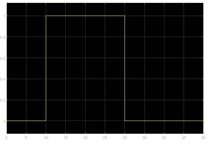
Thermistor sense the temperature and turn on or off according to the required condition.