Week 3 - External flow simulation over an Ahmed body.
- AIM: External flow Simulation over a Ahmed Body.
- Objective: To perform the simulation over an Ahmed Body with an inlet velocity 25m/sec, drag coeffient 0.33.
- Introduction:(Q1) An Ahmed body is an bascically a 3D model that is a prototype of car for the simullation of CFD/ANASYA,it helps to variefy the newely developed Simulation software by satisfying the standard results of this Ahmed Model,So now we are going to create a simulation over an same model for inlet velocity 25m/s.
- (Q2) the negative pressure in the weak region might be becase of the low input velocity,or might be becasuse of choosing the factor of reylond number i.e is kEpsilon. or many more factors.
- Solving & Modelling approach:
- Firist we need to downlaod the model from the given source,i.e is ahmed body.
- next in the Ansa workbench we need drag & drop the Ansa fluent .
- than in geometry we need to get model on work space need to create rthe required geometry to it.
- Than go for meshing part create the required meshing over the model
- than go for setup part, set the required conditions for setup the simulation over the model.
- than go for solution part,create the required contours to be done for the solution part,thn run the calculations .
- thn compare the results.
-
Pre-processing and solver setting :
- first in pre-processing
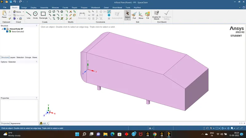
- open the geometry, get the model on the new space claim workbench.
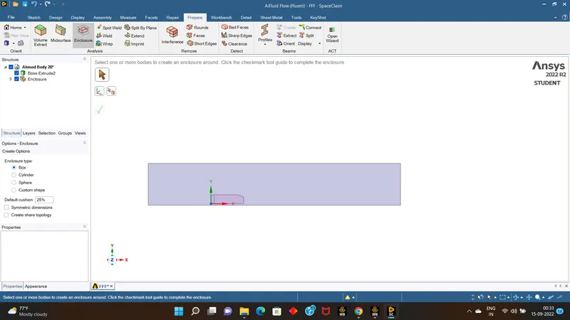
- Than come to prepare tool bar select enclosure tool ,and click on the model so we can visible the enclosure over the model ,nw we have to assign the measurment over the enclosure.
- now close the geometry part & open the meshing part.
- after opening meshing part we will name the each parts with particular parts.
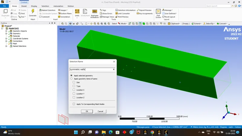
- than select the each enclouser & click f8 to invisible that enclosure ,after making all the enclousre invisible .
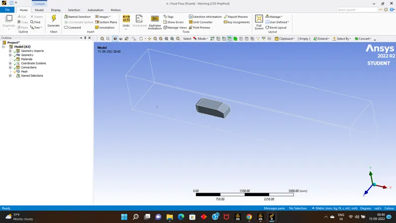
- than using the box selection select the car & name it as car walls .
- Next go for meshing the model
- after meshing go for section view,and we can see even the car area is still present so we need to reomove it .
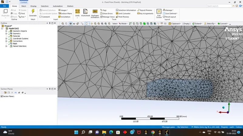
- now exit this meshing & go back to geometry and select the model and supress it for physics, create the plains at center of the global axis.
- & than come back to meshing part clear the mesh & generate the mesh.
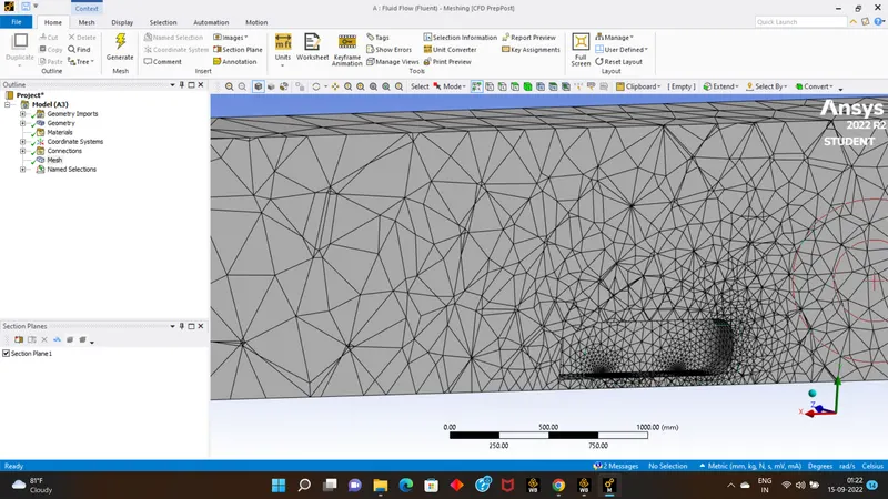
- close the mesh part & open the setup part for further procedure.
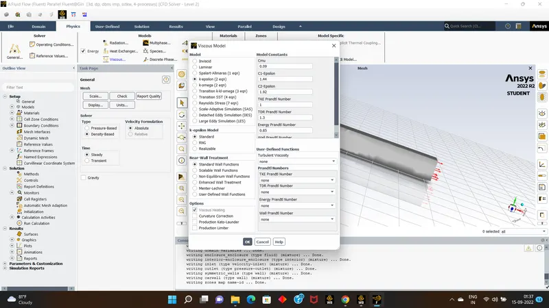
- for solver type select the density based type ,select energy eqn, for viscous select k-epsilon.
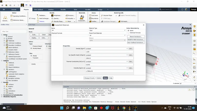
- add materials as air asusall.
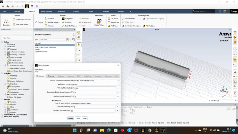
- next click on boundry conditions, in tht inlet value as 25 m/s, outlet velocity will be 0.
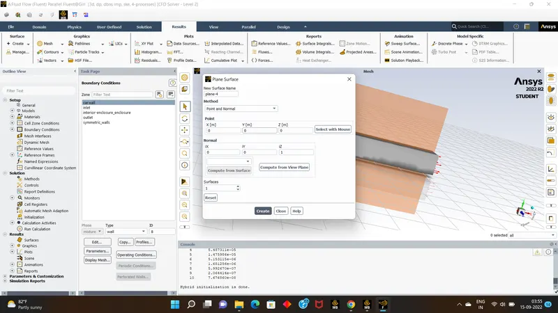
- Than go for results ,there using a surface tool we need to create a plane which is normal to z-axis.
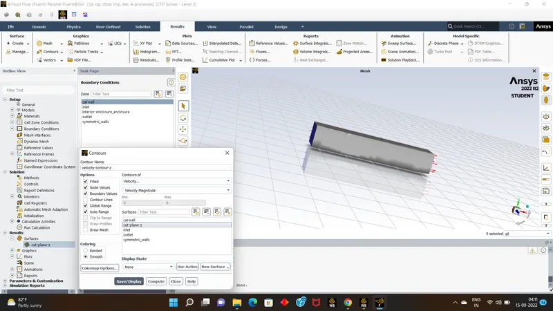
- next go to contours create new contour profile of velocity contour for cut plain.
- Than go back to solution create an solution annimation as velocity animations.
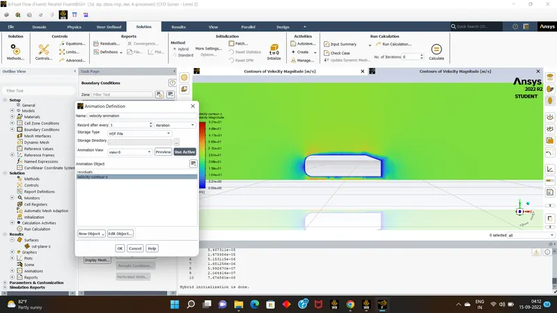
- nxt run the calculations for 500 itirations & see the results.
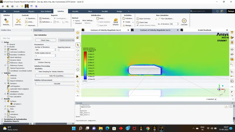
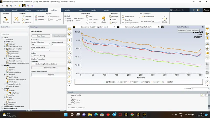
- Solver Settings:
- Again go back to geometry parts to modify the existing model to obtain the accurate results.
- again create an small enclosurearound the model to refine the meshing as well as results.
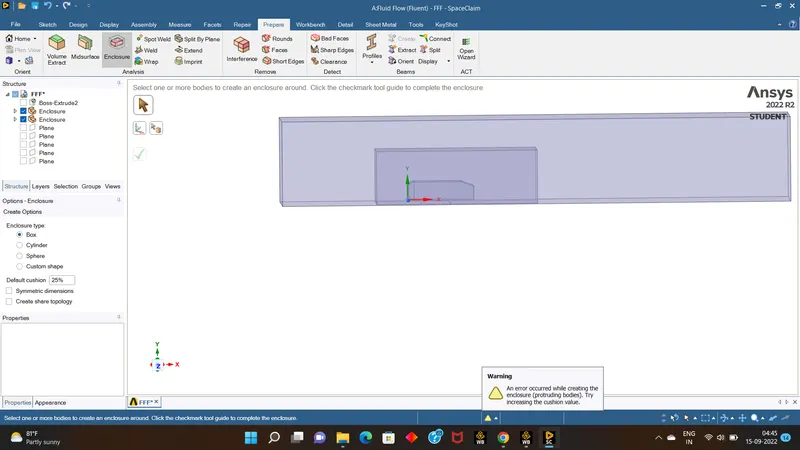
- after preparing the inside enclosure volume will be merged with large enclosure so we have to disable it by using tools interface in prepare & thn to visualize the hatches turn the the hatches option.
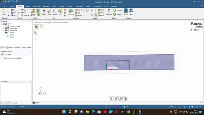
- now exit from the geometry & open meshing part.
- first clear the mesh generation,than generate the mesh over the model,we can see the uniform meshing over the 2 enclousres.
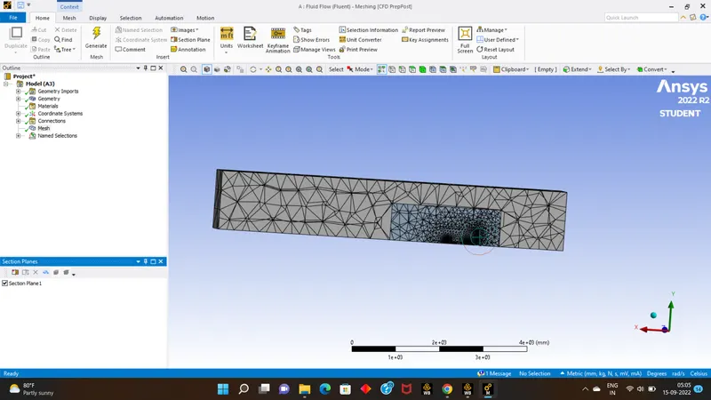
- than click on the mesh tool over right mouse button than go for method and choose the outer enclosure,than choose multizone mesh length as 100mm & generate the mesh.
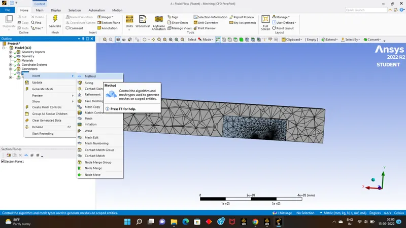
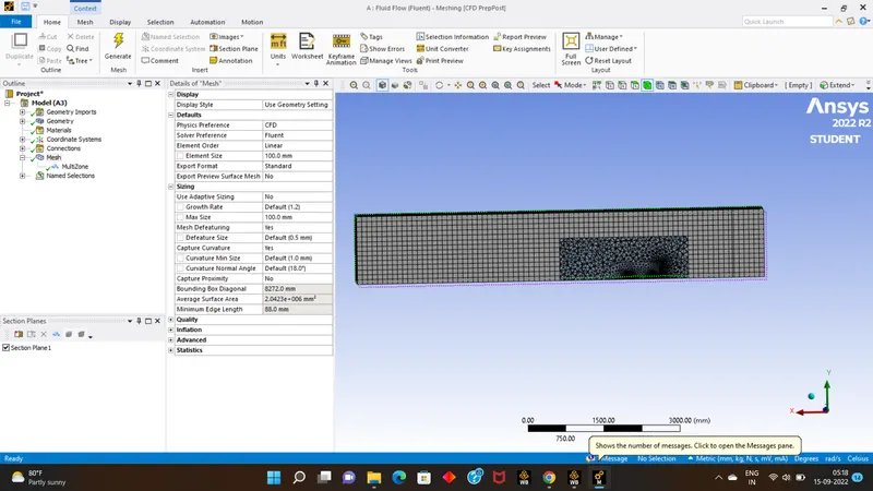
- than again go mesh and right click over mouse than select body sizing & select the car wall & give target length as 50
- still the surface is not yet finished finely so we need to choose face selection & again do the sizing for target length 5 and generate the mesh .
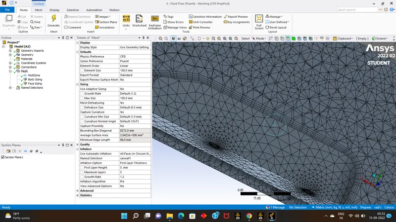
- than we need to do infliation over the car wall, so choose infilation,select the all faces selection & select 5 as number of layers & update the mesh .
- than close the mesh part & update it,& open setup part
- than check for the setup option if the present asusal nothing to chance else give the proper boundry conditions.
- finally initalize & than run for 500 itrations.
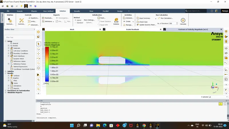
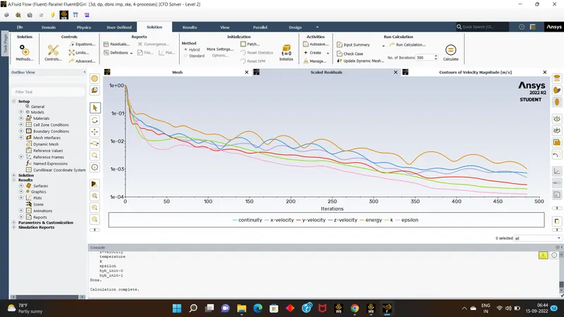
- close the setup part & move to the results section.
- Results:
- Than go to reults section than make the car wall visible & make an edit with varible constant for pressure.
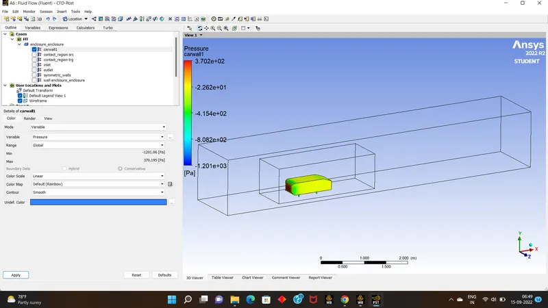
- than create a plane at xy plane & name it as cut plane & assign with pressure variable & click on apply.
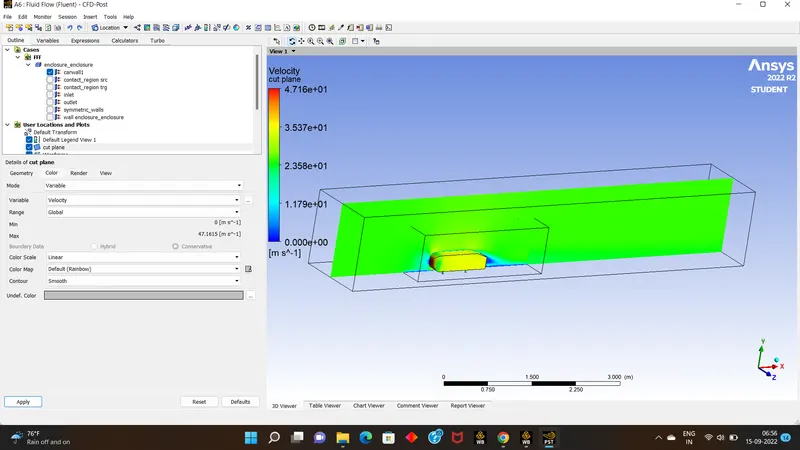
- we can also aplly mesh lines ove the cut plane by unabling the mesh line options.
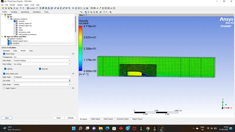
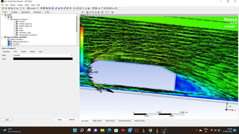
- Than we need to create the vectors over the cut planes.
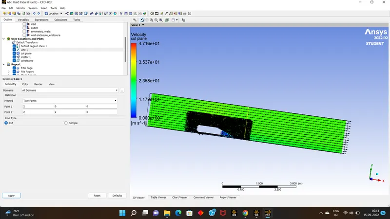
- than we can create the lines on the cut plane which helps in analyising the results.
- than go for the location tool & create the chart.
- than we can create the many kines over a single chart,by using the required option.
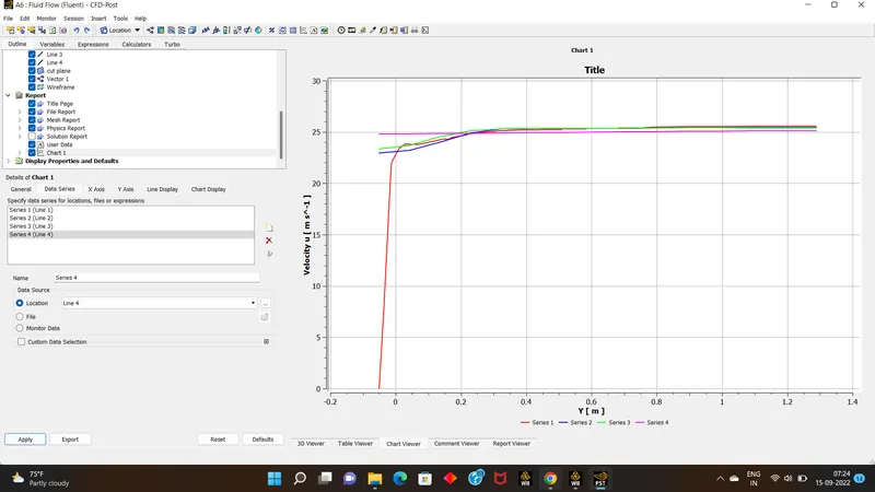
- than can also export the data to ex-cel sheet by using export tool & rename it as data from cfd post.
- Conclusion: On Refining the meshing as comperatively the better results were obtained than the proper target length,when it was updated & refined with geometryic cleanup.