Week 3 - External flow simulation over an Ahmed body.
OBJECTIVE:
We are to run a simulation on Ahmed Body to find answers to the following questions:
-
Describe Ahmed's body and its importance.
-
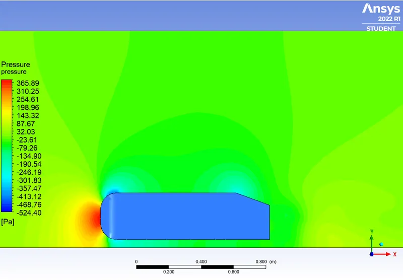
Explain the reason for the negative pressure in the wake region.
-
Explain the significance of the point of separation.
INTRODUCTION:
AHMED BODY:
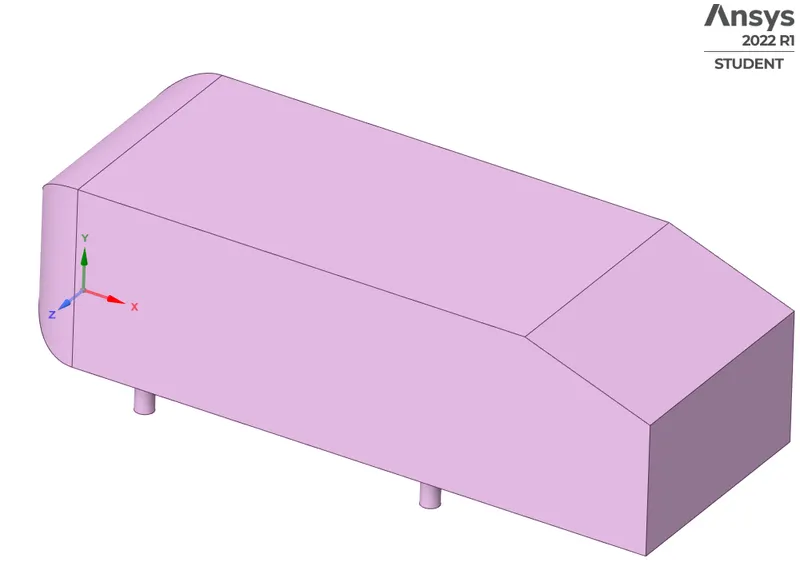
Ahmed body is a standard wind tunnel model of a generic car shape.
The airflow around the Ahmed body captures the essential flow features around an automotive and was first defined and characterized originally by S. R. Ahmed in 1984 [1]. Although it has a very simple shape, Ahmed body allows us to capture characteristic features that are relevant to bodies in the automotive industry.
Importance:
Engineers working in vehicle aerodynamics use Ahmed body to validate their numerical model because the experimental data from wind tunnel testing is available for Ahmed body. Once the numerical model is validated, it is used to design new models of the car.
GEOMETRY:
We have the standard Ahmed Body:
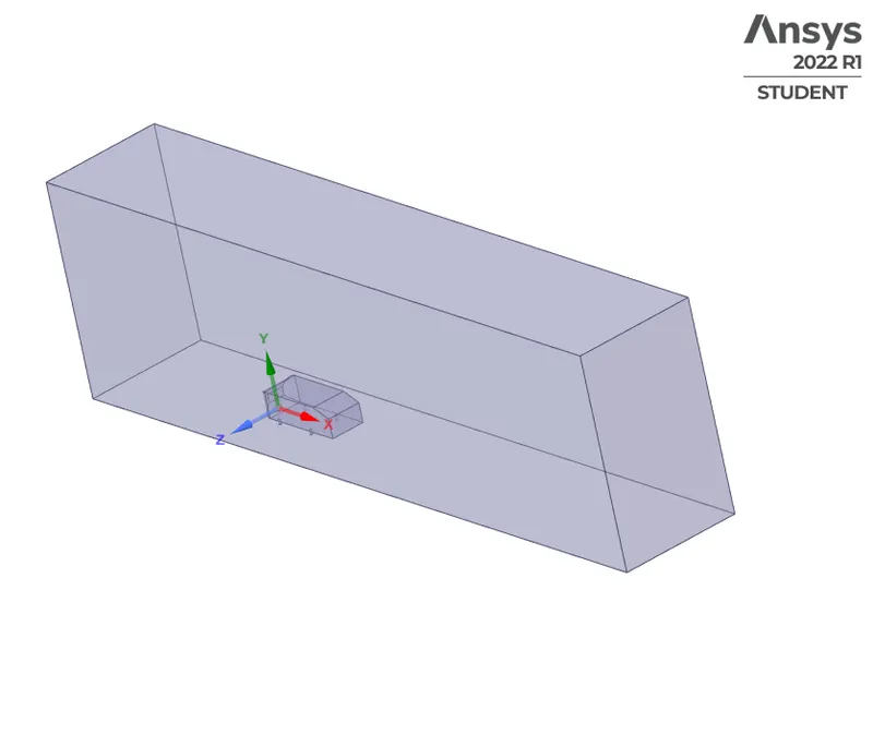
We will enclose the Ahmed Body to Simulate a Wind Tunnel using the enclosure option in SpaceClaim:
We will create another enclosure which closely follows the ahmed body to create a refined mesh near the ahmed body. Yhis will facilitate a more accurate study of flow characteristics near the walls of Ahmed Body without any extravagant increase in the cell count.
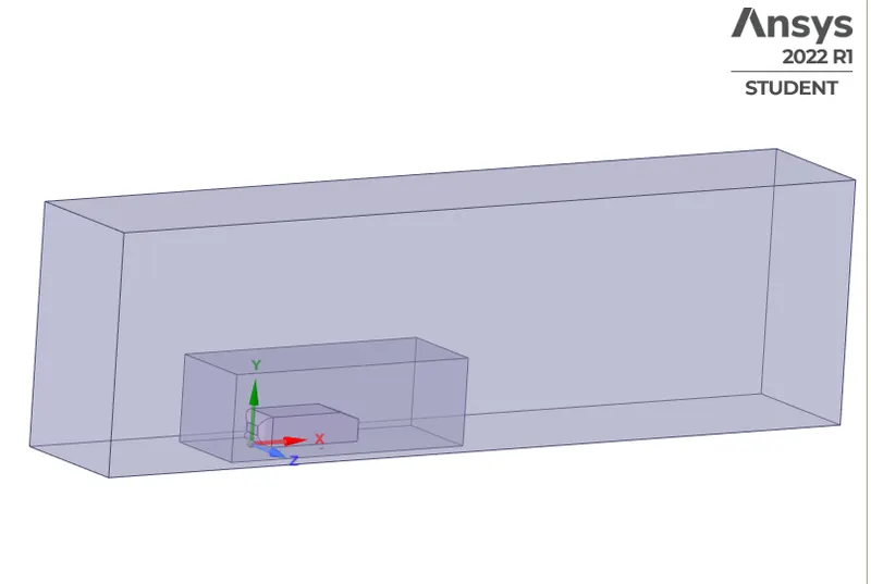
These two enclosures will interfere with one another so we need too fix it, clicking on interferences shows the interfering geometry:
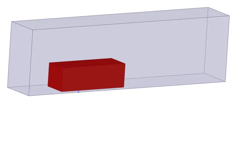
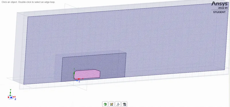
Interferences tool fixes it simply by clicking on the check green tick:

We will split the body since the nodes on the academic license of
MESHING:
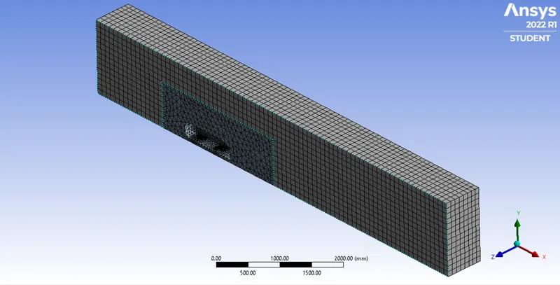
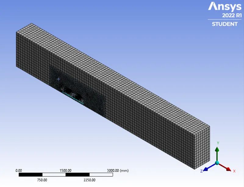
We are using the MultiZonal Method for creating Mesh, with an element size of 100 mm:
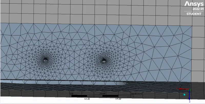
The base of Ahmed Body, refined since the legs appear to be polygonal instead of circular:
We will be simulating 3 cases, this forms our baseline case, we will go define our case with this mesh and refine it as we proceed.
SETUP AND SOLUTION:
We will use K-Omega SST Model since we are interested in observing the flow characteristics near the car wall and it holds good for such flows. We are not interested in the temperature profile so we can turn off the energy equation.
The working fluid is air with Ansys-default properties.
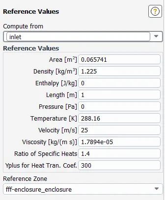
Reference Values are set as shown below:
RESULTS:
BASELINE CASE:
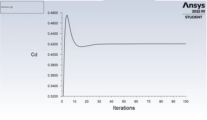
DRAG:

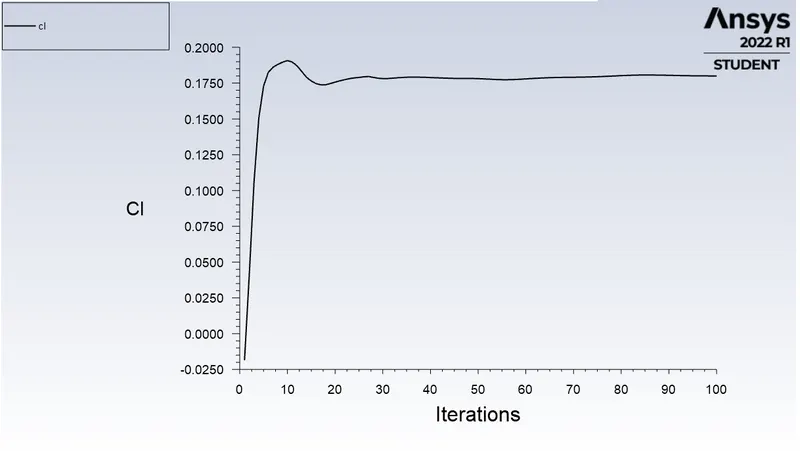
LIFT:

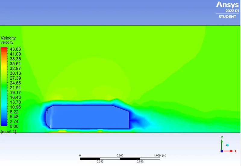
VELOCITY CONTOUR:
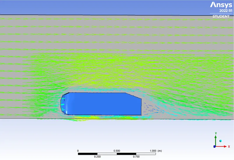
VELOCITY VECTOR:
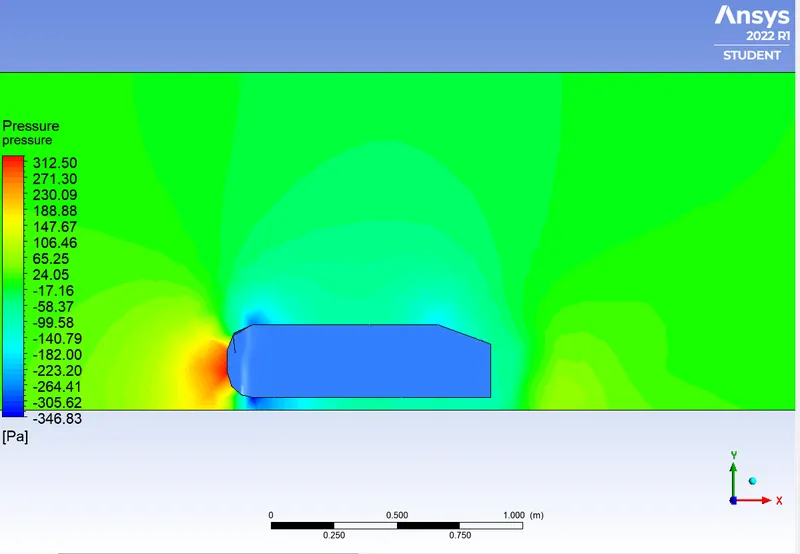
PRESSURE CONTOUR:
REFINED CASE:
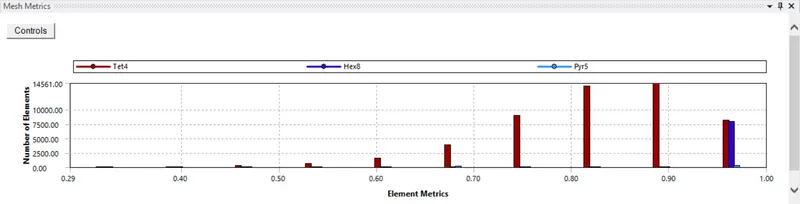
The mesh is refined with the inner enclosure element size as 50mm:
DRAG:
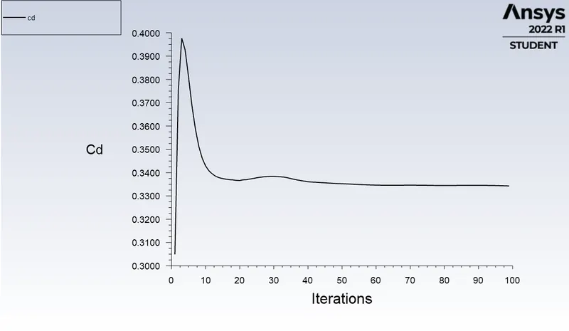

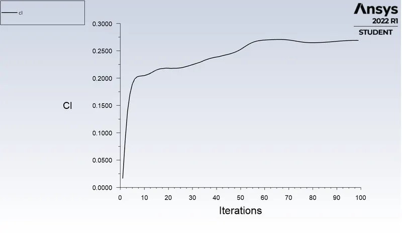
LIFT:

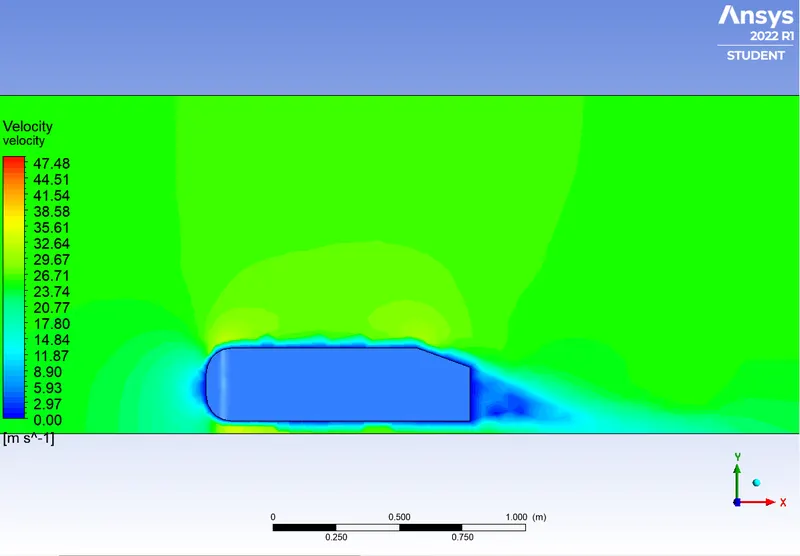
VELOCITY CONTOUR:
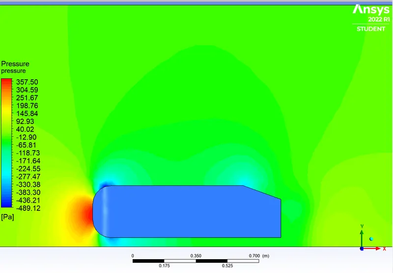
PRESSURE CONTOUR:
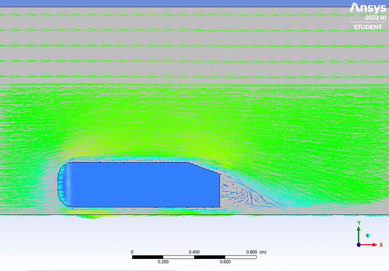
VELOCITY VECTOR:
REFINED CASE WITH YPLUS:
To further enhance our mesh we will be using a wall function called yplus to calculate how much refinement is needed near the walls. Mathematically, yplus is given as :
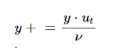
where `y` is the distance from the wall,
`u_t` is frictional velocity given by : 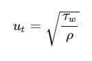
`tau_w` is wall shear stress given by : 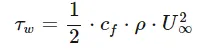
`U_(oo)` is free stream velocity:
`C_f` is skin friction coefficient given by: 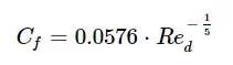
We will use these parameters to calculate our first layer thickness for yplus = 30.
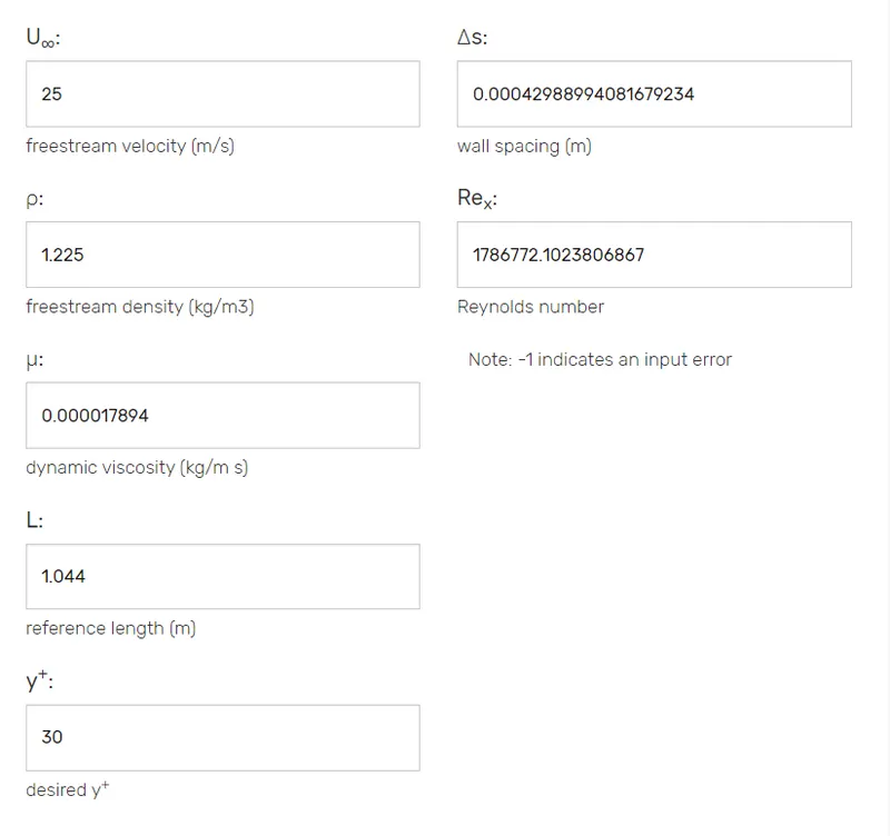
https://www.cadence.com/ko_KR/home/tools/system-analysis/computational-fluid-dynamics/y-plus.html
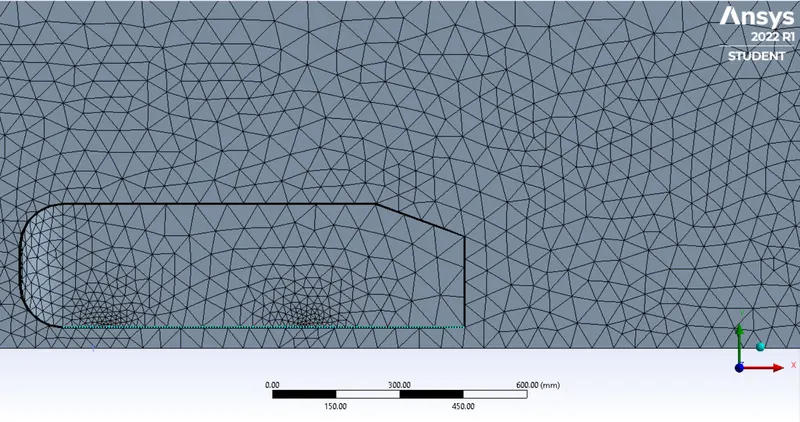
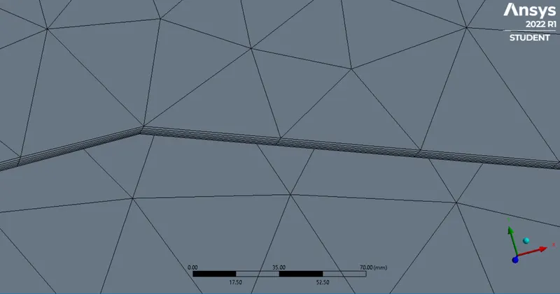
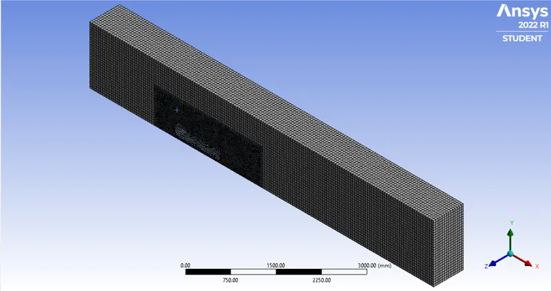
We will also reduce the element size to 50mm on the outer enclosure and 30mm on the inner enclosure:
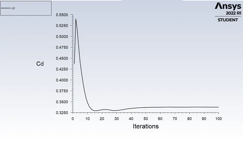
DRAG:

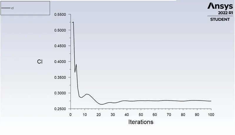
LIFT:

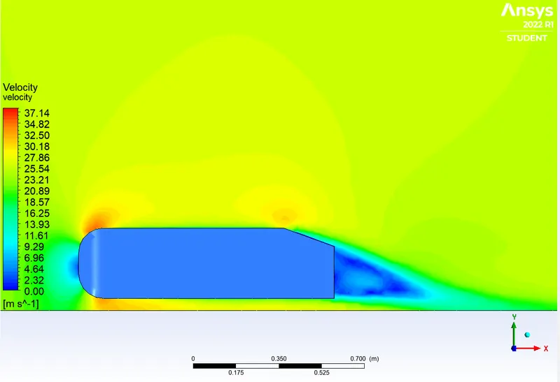
VELOCITY CONTOUR:
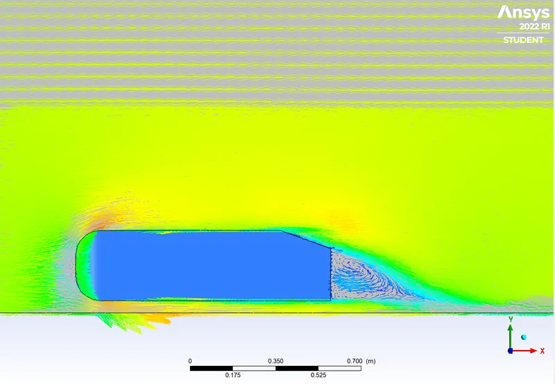
VELOCITY VECTOR:
PRESSURE CONTOUR:
CONCLUSIONS:
CAUSE OF NEGATIVE PRESSURE:
We can see that the wake region is accompanied by vortex formation via the vector plots. As a result of the flow separation along with vortex formation, the region becomes high vorticity region and has high kinetic turbulent energy. Since Energy is conserved, this increase in turbulent kinetic energy is supported by a decrease in pressure.
SIGNIFICANCE OF THE POINT OF SEPARATION:
The point of separation is the point where the boundary layer leaves the solid body. It has significance as after the boundary layer has separated, the resulting flow becomes turbulent and brings along accompanying effects such as pressure drag. Depending on the Application, knowing the point of separation can help us modify other parameters to move the point of separation accordingly and have more control over flow separation.
GRID DEPENDENCE TEST:
| MESH TYPE | OUTER ENCLOSURE MESH SIZE | INNER ENCLOSURE MESH SIZE | yplus | `C_d` | `C_l` |
| Baseline | 100 mm | 100 mm | No | 0.42 | 0.18 |
| Refined | 100 mm | 50 mm | No | 0.33 | 0.26 |
| Refined with Yplus | 50 mm | 30 mm | 0.4298 | 0.33 | 0.27 |
It can be inferred that:
- A coarse mess gives inaccurate results.
- A basic refined mess is good enough to provide accurate values. Further refinement can be avoided to save computational power and time.
- However, if there is a need to accurately understand the flow and observe the undergoing phenomena that numbers can't show, then we need to use mesh enhancing methods - yplus in our case