Week 3 - External flow simulation over an Ahmed body.
AIM:
The aim of this assignment is to simulate external flow over an Ahmed body.
OBJECTIVE:
The objectives of this assignment are:
- Describe Ahmed's body and its importance.
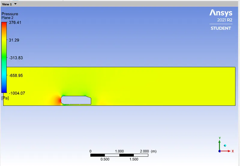
- Explain the reason for the negative pressure in the wake region.
- Explain the significance of the point of separation.
- To simulate external flow over an Ahmed body.
- To get the different plots and contours.
- To perform a grid independency test
INTRODUCTION:
AHMED BODY:
- The Ahmed body simplified car geometry constitutes a reference model. It is a parallelepiped with a streamlined front part and a slanted surface at the rear that reproduces the basic flow features of the rear part of ground vehicles. Ahmed et al. (1984) pointed out that the flow is mainly controlled by the slant angle (for a given Reynolds number) and suggested a classification of the averaged flow topologies. The case of a slant angle of 25 is particularly interesting, since this configuration presents a complex organization of the flow with a high drag level and is representative of the flow topology at the rear part of common fastback cars (rear window and rear part). In that case, the flow is characterized by a complex combination of three structures: two longitudinal vortical structures, a 3D separation bubble on the rear window, and a 3D wake located at the rear base.
- Despite the considerable deviation of its geometry from usual vehicles, the body represents the basic aerodynamic properties of a vehicle, especially in the rear part. The slant angle ϕ has a strong influence on the aerodynamic drag and lift at the back. Both the drag and lift coefficients change abruptly at the angle ϕ=30°. Therefore, this angle is called the critical slant angle.
- We investigate the influence of the slant angle by measurements at ϕ = 25° and 35°. For slant angles ϕ ≤ 30°, an inward rotating pair of vortices with increasing strength is generated, as observed at fastback vehicles. Therefore, the Ahmed body with the slant angle of 25° belongs to the fastback vehicles, which exhibit very strong inward rotating longitudinal vortices at the C-pillars. These vortices extend far into the wake and generate a field of downwind in the enclosed region. At a slant angle of 30°, i.e., directly before transition to the full square back flow, this pair of vortices is developed most strongly, and the flow separates at the lower edge of the slant. This produces strong under pressures at that position, so that the aerodynamic drag reaches its maximum in this state. The Ahmed body used for the measurements was built from wooden materials in the original dimensions shown in Figure 1. The rear part was interchangeable, so as to realize the two slant angles to be investigated with the same front part of the body.
SIGNIFICANCE
- Increasing growth of the number of road transportation vehicles and hence fossil fuel consumption have raised air pollution level to alert status in many cities. In this regard, considering international policies for reducing the consumption of fuels and greenhouse gases generated by motor vehicles, researchers in the field of car aerodynamics have tried to minimize the resisting force generated as air flow hits the vehicles. The lower amount of this force (known as drag force), the lower will be its fuel consumption and pollutant emission. This force can only be controlled by accurate characterization of the flow pattern. Since experimental study of flow control accurately and comprehensively is an expensive and time-intensive practice due to differences in their apparent structures, and the fact that, it is not reasonable to generalize the results of such studies to other cases, it will be a useful practice to present a simple and standard model of a vehicle with similar flow pattern to that of an actual car. Therefore, a model known as Ahmed body model is referred to which resembles three-dimensional flow pattern of an actual car due to the rear slant angle behind that.
-
In research works, active and passive flow controls were adopted in the tailing section of the model in an attempt to modify the flow in this region and reduce the drag force applied to the model. Installation of various types of deflectors is the passive flow control method which require no external energy. Uncontrollable performance is a disadvantage of this method. Active control methods such as mixed jets pulse jets and fluidic oscillators are paid attention because of their controllable nature which allows them to be turned on/off on demand. In the experiment, the flow separates right at the corner of the sloping surface and it reattaches in the middle of the surface.
-
It is mentioned that alpha=30° is a critical slant angle for which the topology of the flow is suddenly modified and accompanied by an important decrease of the drag. For subcritical angles, the outer flow may remain attached on the slant, if alpha<=12.5°, or may partially detach when increasing the incidence up to alpha=30°, then forming a confined recirculation zone. This separation generates a sufficiently strong pressure gradient between the bluff body sides and the slant that brings on the rolling up of the streamlines at the two upper corners of the slant, thus forming two strong contra rotating vortices. These strong vortices are responsible for the high drag induced drag. This phenomenon is similar to the one occurring on a finite-span wing with a flap of increasing angle of attack. On the contrary, for supercritical angles, the flow totally separates on the slant. This involves a decrease of the previously detailed pressure gradient that inhibits the formation of the strong trailing vortices and consequently induces a decrease of the drag.
NEGATIVE PRESSURE IN THE WAKE REGION:
- The fluid that is flowing over the Ahmed body produces shear forces on the wall of the body due to the viscosity of the fluid so in order to compensate this force the walls produce a force opposite to the force produced by the flowing fluid in order to maintain the equilibrium.
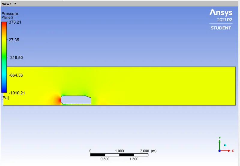
- In the Wake region the flow separates and Stagnation point is created due to sudden change in the geometry of the vehicle.
- The velocity at the Stagnation point is 0 and the Stagnation pressure is composed of two pressure values one is the static pressure and the other is the dynamic pressure.
- Flow separation occurs due to the adverse pressure gradient that occurs in that region.
- Pressure gradient is an is one of the factors that influences a flow immensely. It is easy to see that the shear stress caused by viscosity has a retarding effect upon the flow. This effect can however be overcome if there is a negative pressure gradient offered to the flow. A negative pressure gradient is termed a favorable pressure gradient. Such a gradient enables the flow.
- One of the severe effects of an adverse pressure gradient is to separate the flow.The geometry of the surface is such that we have a favorable gradient in pressure to start with and up to a point P. The negative pressure gradient will counteract the retarding effect of the shear stress (which is due to viscosity) in the boundary layer.
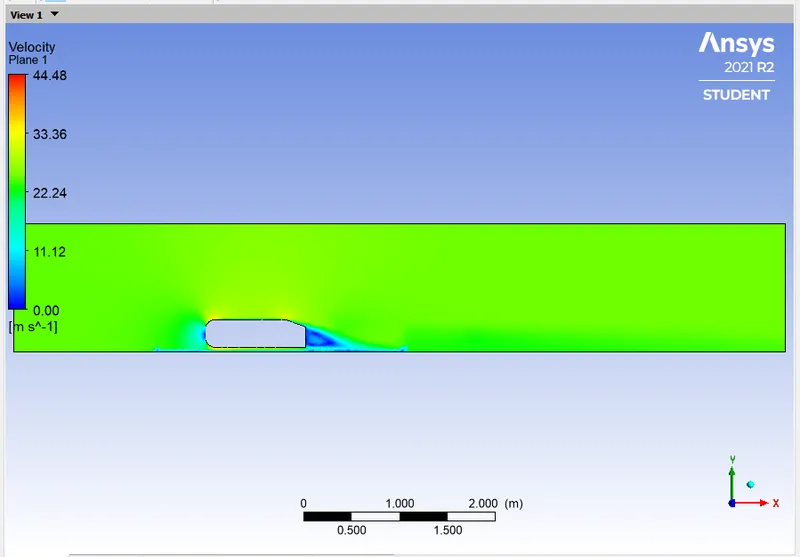
- The adverse pressure gradient begins to retard. This effect is felt more strongly in the regions close to the wall where the momentum is lower than in the regions near the free stream. As indicated in the figure, the velocity near the wall reduces and the boundary layer thickens. A continuous retardation of flow brings the wall shear stress at the point S on the wall to zero. From this point onwards the shear stress becomes negative and the flow reverses and a region of recirculating flow develops. We see that the flow no longer follows the contour of the body. We say that the flow has separated. The point where the shear stress is zero is called the Point of Separation.
- Due to these reasons the pressure at the wake region is negative.
SIGNIFICANCE OF POINT OF SEPARATION:
-
Whenever there is relative movement between a fluid and a solid surface, whether externally round a body, or internally in an enclosed passage, a boundary layer exists with viscous forces present in the layer of fluid close to the surface. Boundary layers can be either laminar or turbulent. A reasonable assessment of whether the boundary layer will be laminar or turbulent can be made by calculating the Reynold's number of the local flow conditions.
Flow separation or boundary layer separation is the detachment of a boundary layer from a surface into a wake. Separation occurs in flow that is slowing down, with pressure increasing, after passing the thickest part of a streamline body or passing through a widening passage, for example.
Flowing against an increasing pressure is known as flowing in an adverse pressure gradient. The boundary layer separates when it has travelled far enough in an adverse pressure gradient that the speed of the boundary layer relative to the surface has stopped and reversed direction. The flow becomes detached from the surface, and instead takes the forms of eddies and vortices. The fluid exerts a constant pressure on the surface once it has separated instead of a continually increasing pressure if still attached. In aerodynamics, flow separation results in reduced lift and increased pressure drag, caused by the pressure differential between the front and rear surfaces of the object. It causes buffeting of aircraft structures and control surfaces. In internal passages separation causes stalling and vibrations in machinery blading and increased losses (lower efficiency) in inlets and compressors. Much effort and research has gone into the design of aerodynamic and hydrodynamic surface contours and added features which delay flow separation and keep the flow attached for as long as possible. Examples include the fur on a tennis ball, dimples on a golf ball, turbulators on a glider, which induce an early transition to turbulent flow; vortex generators on aircraft.
METHODOLOGY:
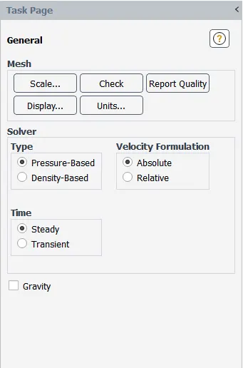
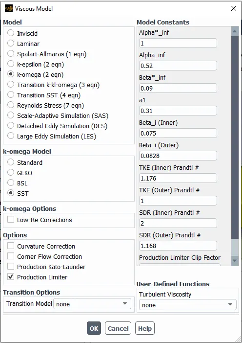
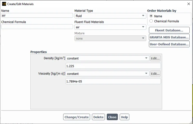
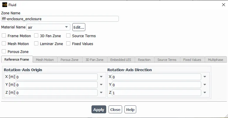
The simulation of external flow over an Ahmed body is done using Ansys Fluent.
CAES - 1:
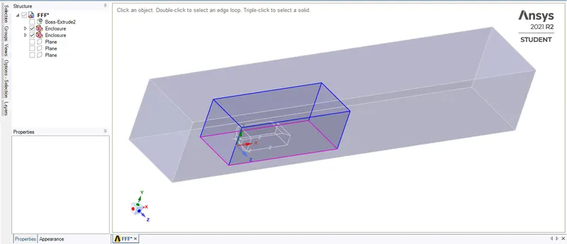
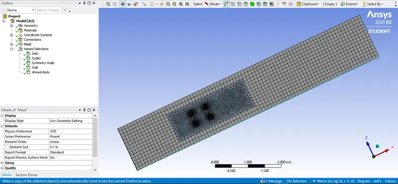
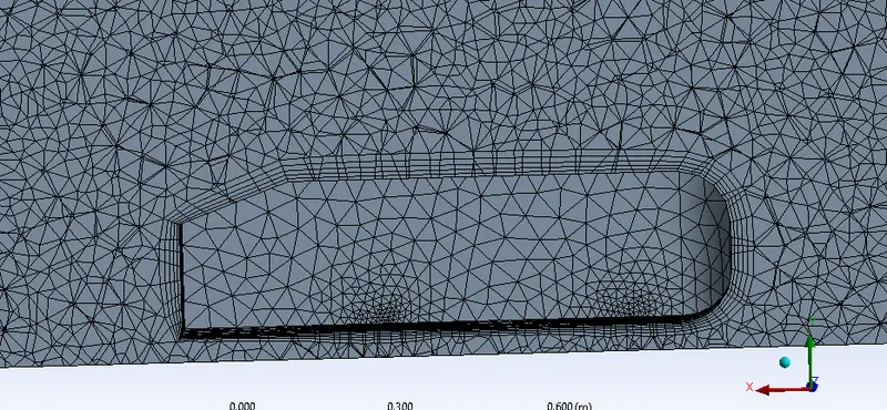
- Outer block elements size = 0.1m
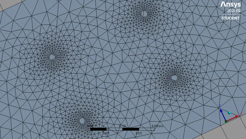
- Inner block element size = 0.05m
- Legs of Ahmed body = 0.005m
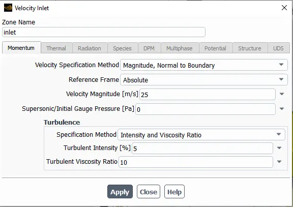
- Inlet Velocity = 25m/s
GEOMETRY:
MESHING:
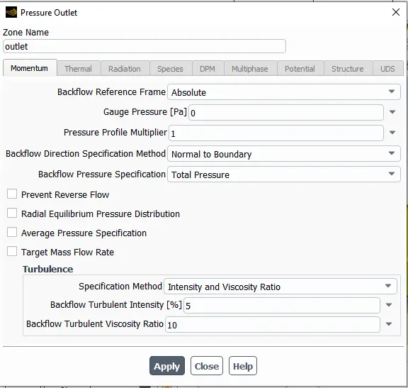
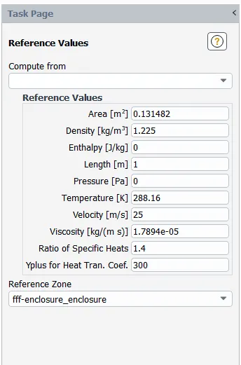
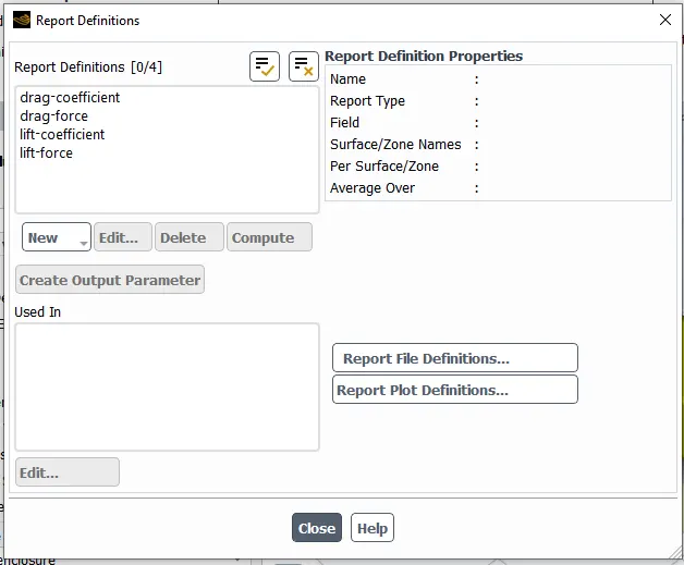
SETUP:
RESULTS:
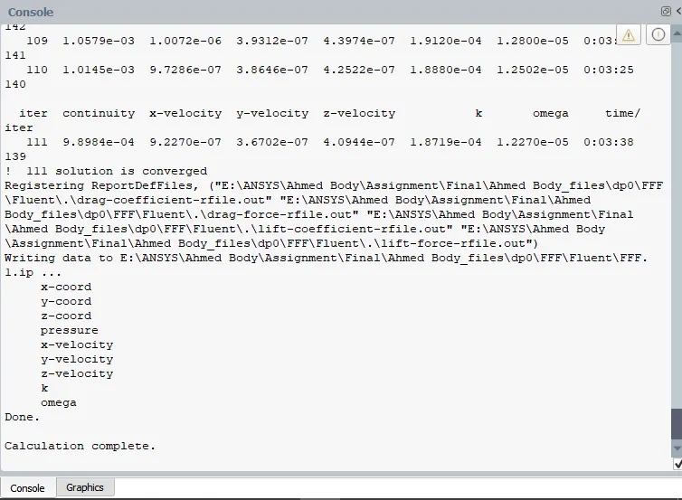
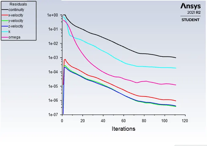
RESIDUALS:
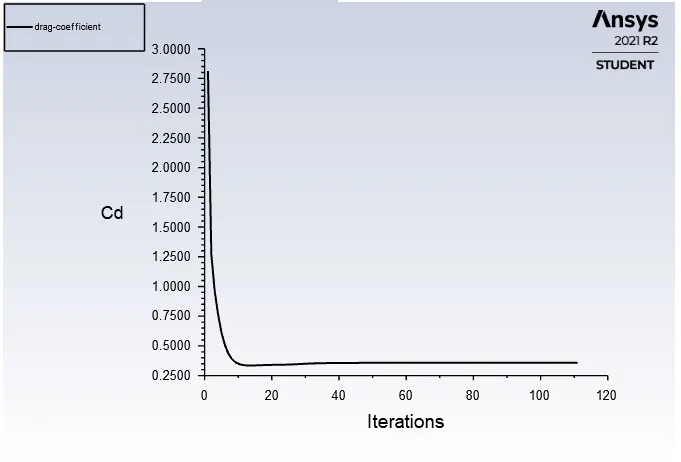
DRAG COEFFICIENT:
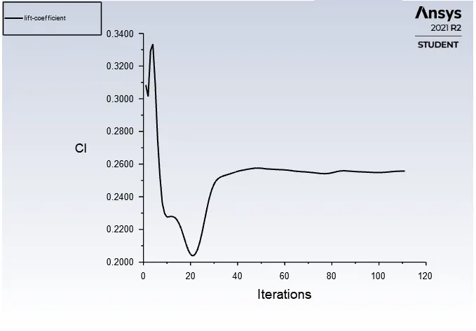
LIFT COEFFICIENT:
VALUES:
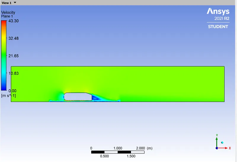
VELOCITY CONTOUR:
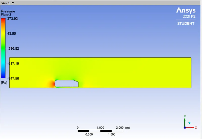
PRESSURE CONTOUR:
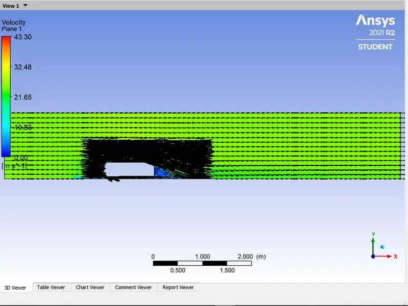
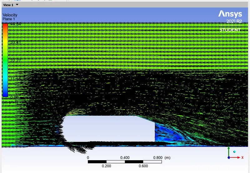
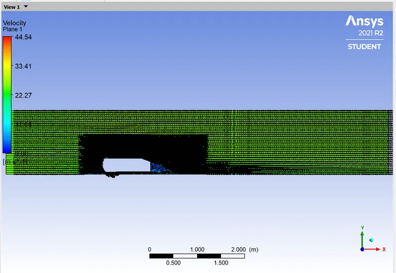
VECTOR PLOT:
CAES - 2:
- Outer block elements size = 0.08m
- Inner block element size = 0.04m
- Legs of Ahmed body = 0.004m
- Inlet Velocity = 25m/s
GEOMETRY:
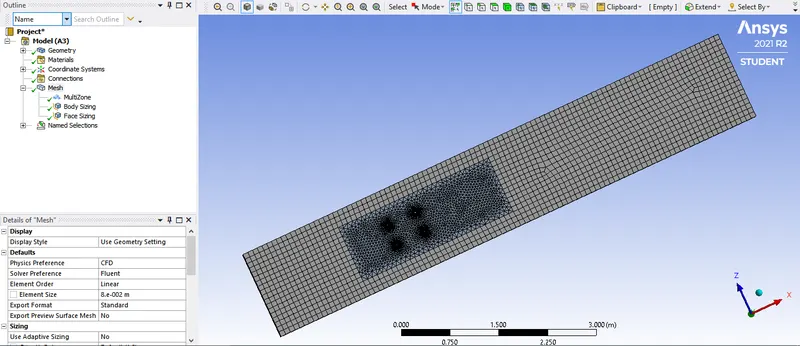
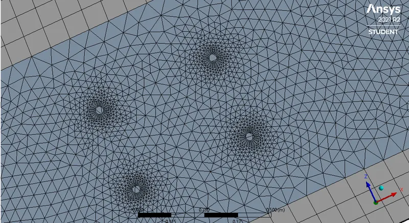
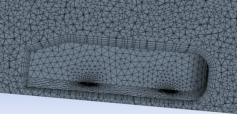
MESHING:
SETUP:
RESULTS:
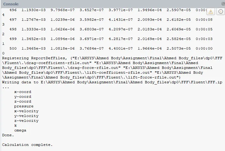
RESIDUALS:
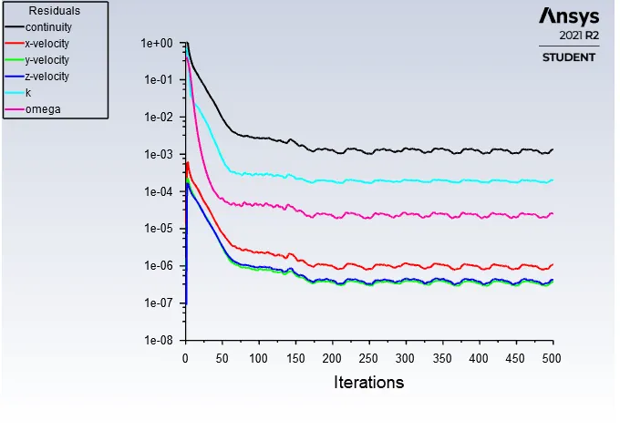
DRAG COEFFICIENT:
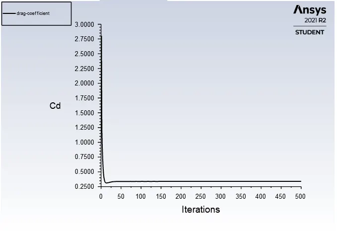
LIFT COEFFICIENT:
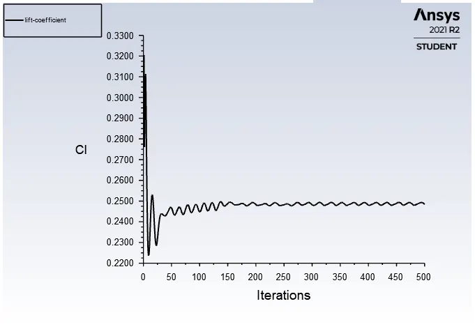
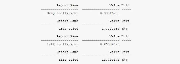
VALUES:
VELOCITY CONTOUR:
PRESSURE CONTOUR:
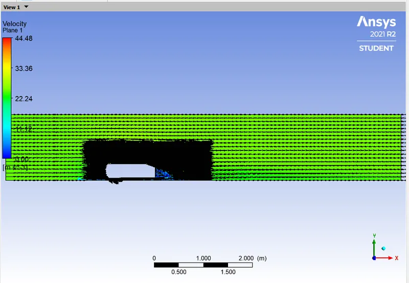
VECTOR PLOT:
CAES - 3:
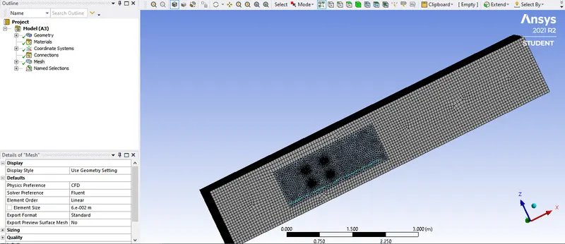
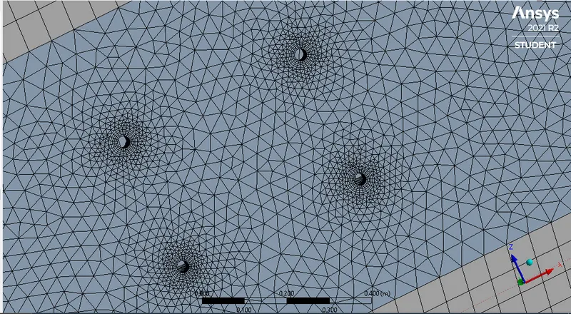
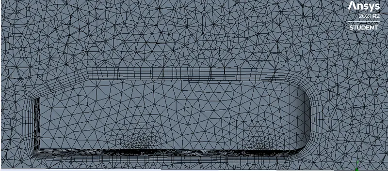
- Outer block elements size = 0.06m
- Inner block element size = 0.04m
- Legs of Ahmed body = 0.004m
- Inlet Velocity = 25m/s
GEOMETRY:
MESHING:
SETUP:
RESULTS:
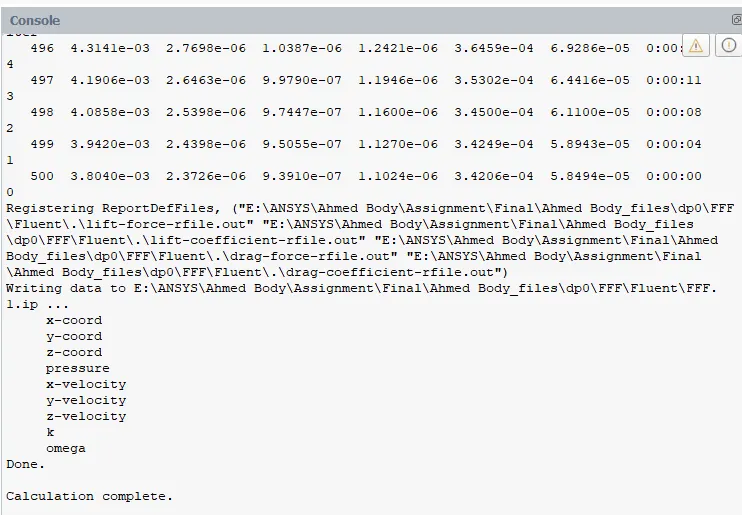
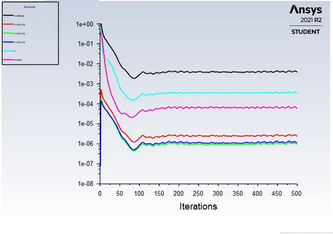
RESIDUALS:
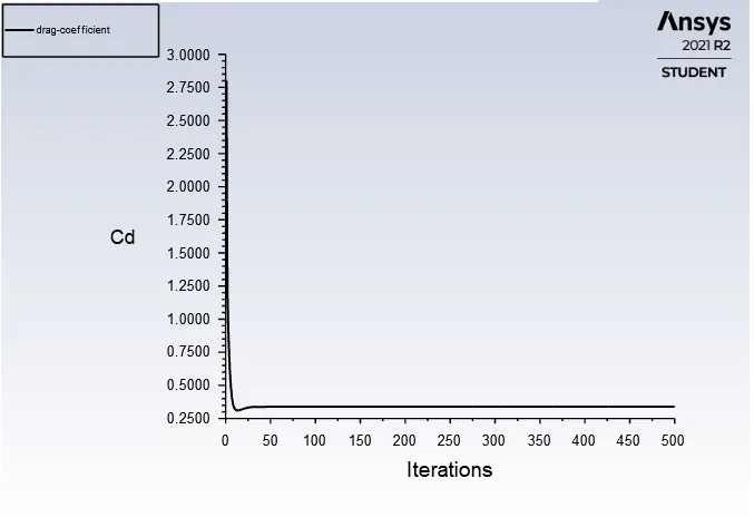
DRAG COEFFICIENT:
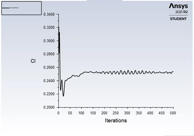
LIFT COEFFICIENT:
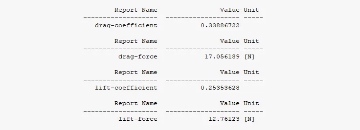
VALUES:
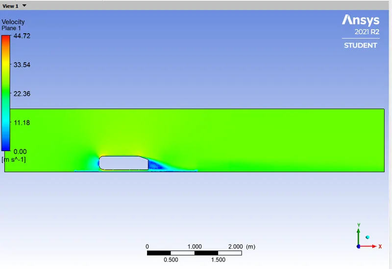
VELOCITY CONTOUR:
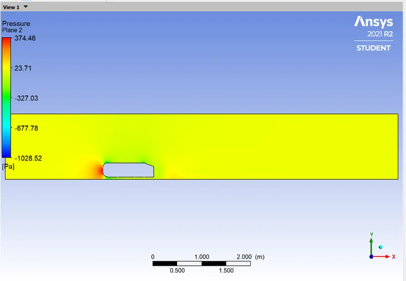
PRESSURE CONTOUR:
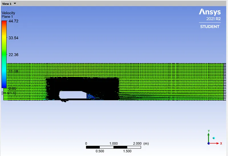
VECTOR PLOT:
CAES - 4:
- Outer block elements size = 0.04m
- Inner block element size = 0.04m
- Legs of Ahmed body = 0.004m
- Inlet Velocity = 25m/s
GEOMETRY:
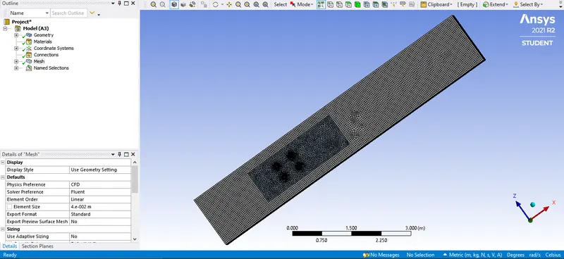
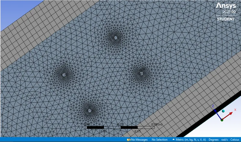
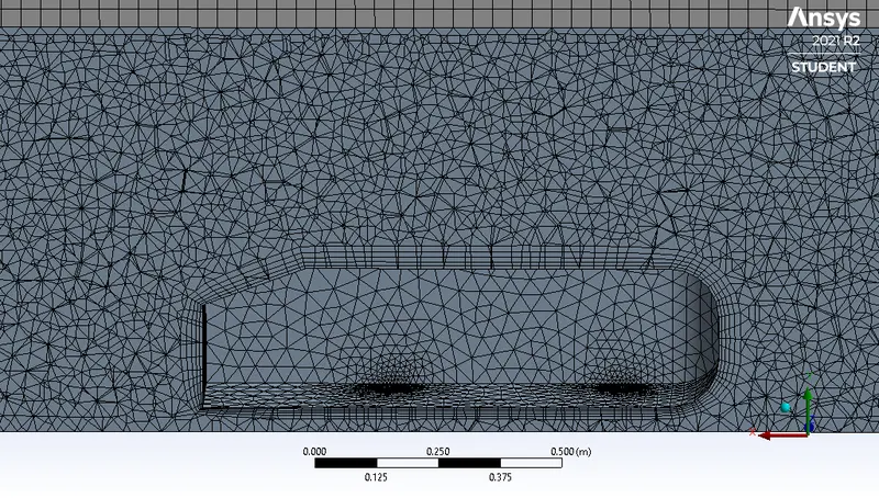
MESHING:
SETUP:
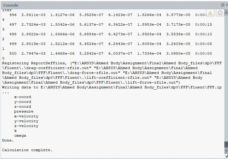
RESULTS:
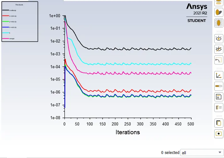
RESIDUALS:
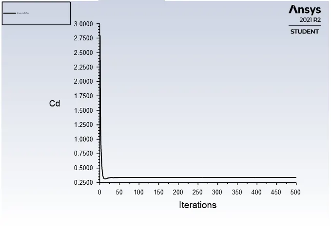
DRAG COEFFICIENT:
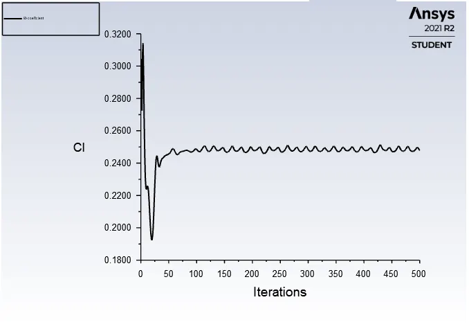
LIFT COEFFICIENT:
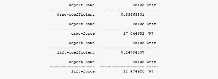
VALUES:
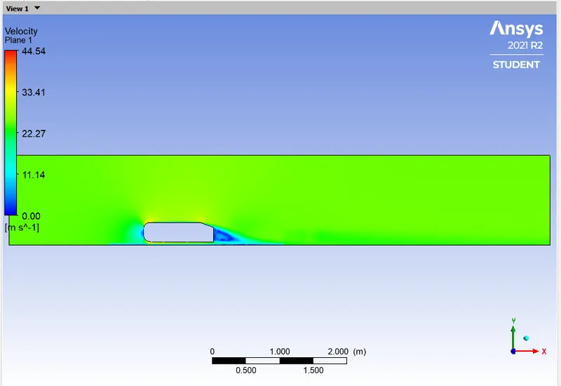
VELOCITY CONTOUR:
PRESSURE CONTOUR:
VECTOR PLOT:
TABULATION:
| SL.NO | NUMBER OF ELEMENTS | COEFFICIENT OF DISCHARGE | DRAG FORCE (N) | COEFFICIENT OF LIFT | LIFT FORCE (N) |
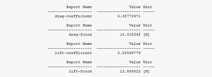
| 01. | 161780 | 0.35772471 | 18.005342 | 0.25568779 | 12.869522 |
| 02. | 292091 | 0.33816788 | 17.020989 | 0.24832978 | 12.499172 |
| 03. | 345611 | 0.33886722 | 17.056189 | 0.25353628 | 12.76123 |
| 04. | 507369 | 0.33863801 | 17.044652 | 0.24784807 | 12.474926 |
From the above table it can be clearly stated that the above problem is grid independent.
CONCLUSION:
- From the above assignment we learnt about the Ahmed body and its significance and found out the drag coefficient, drag force, lift coefficient and lift forces.
- From the above assignment we came to know about the Wake region, Stagnation point and why negative pressure is generated in the Wake region.
- After running the simulation we can observe the regions where flow separation takes place and wakes are formed and negative pressure gradient formed in these regions.
- At last, we can also state that the above problem is grid independent by performing the grid independency test.