External flow simulation over an Ahmed body.
AIM: The present work aims to simulate the external flow over an Ahmed body.
Objectives:
- Describe Ahmed’s body and its importance
- Understand and explain the reason for negative pressure in the wake region
- Explain the significance of the point of separation
- Perform a grid independency test and provide the values of drag and lift for each considered case.
Introduction:
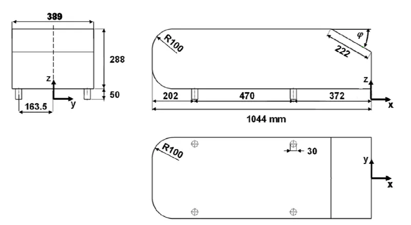
In fluid mechanics, external flow is defined as any motion of a fluid medium that occurs when the medium flows around a completely immersed body in it. Thus, it is of a great importance in aerodynamic studies in domains such as aeronautics and automotive industries. In this work, the external flow is studied over Ahmed body. The case setup is carried out in such a way to mimic the virtual tunnel and post-processing is done in Fluent. The dimensions of the Ahmed body used are given below:
Geometry specifications:
Theory:
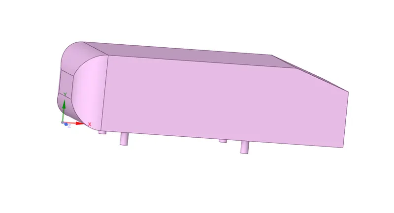
Ahmed body is a simplified car model around which the flow of air captures the essential features around an automobile. This body is used to provide a general reference with a lot of available experimental and numerical data to evaluate the types of flows which exist in car. It is a suitable model for investigations and comparison with benchmark results from various literatures. Using Ahmed body help engineers reduce/avoid going for a car geometry for which getting wind-tunnel data and mesh creating appear to be costly and a lengthy process.
Pre-processing:
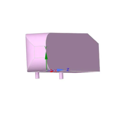
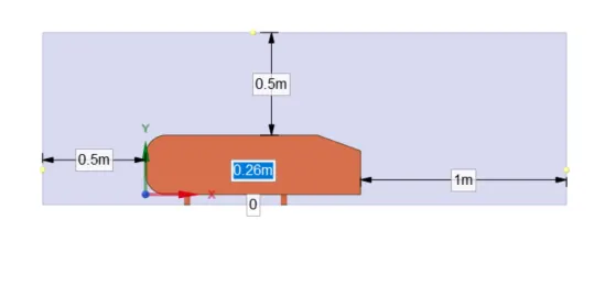
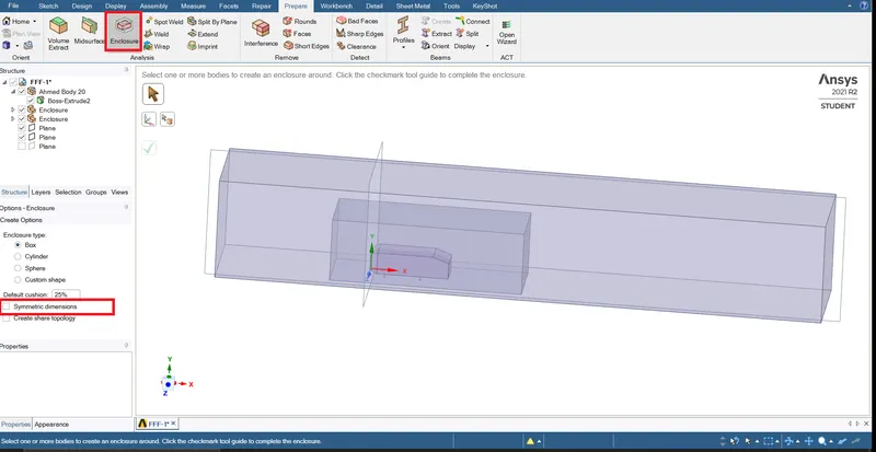
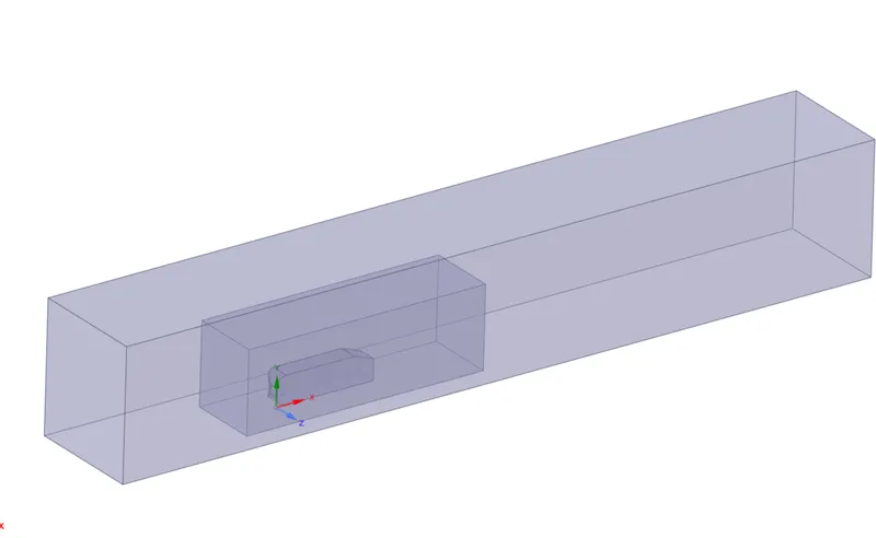
The original CAD model of Ahmed body is in STEP file format. This file is imported in SpaceClaim for cleaning purpose. Since the model has a perfect symmetry, the simulation can be run by considering only half body hence the model is split into two as shown below using the ‘split body’ command in SpaceClaim. Then, for mesh refinement purpose, two enclosures are created which mimic a virtual tunnel of which the dimensions are shown below. Interference as input for meshing phase.
After splitting the body, the enclosures are created for mesh refinement
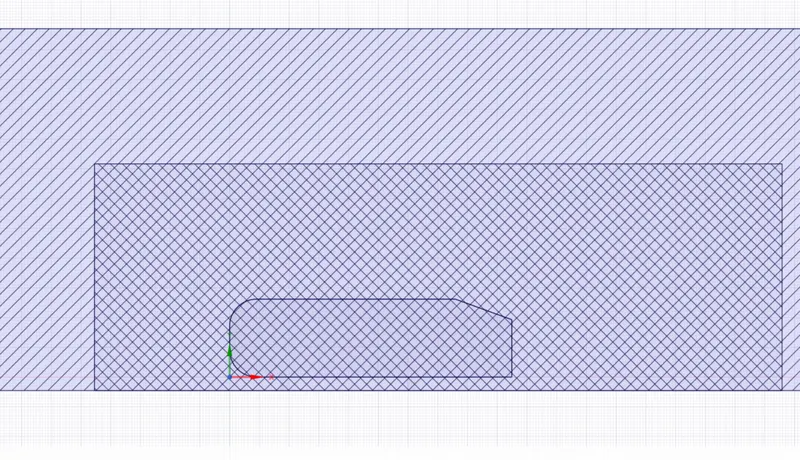
The interference check is done to solve interfering zones problem which may lead to mesh overlapping issues.
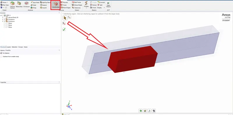
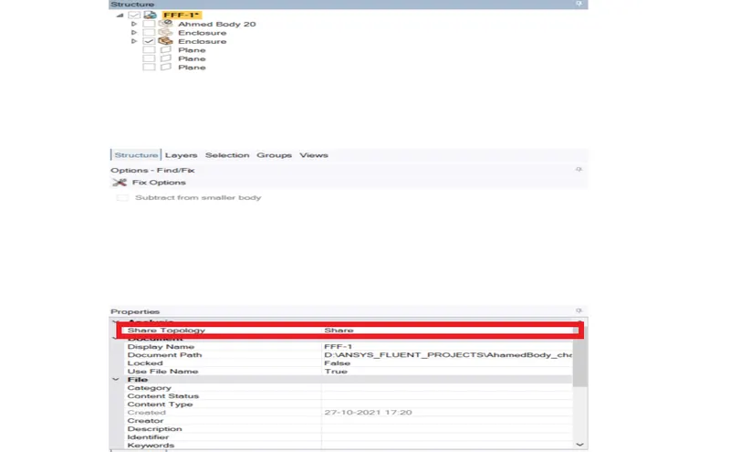
The topology is set to "share" to enable the two enclosures to share informationns with each other.
Mesh:
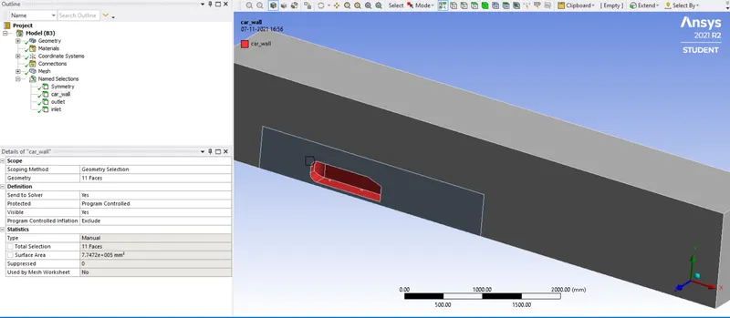
This part started with name selection as shown below:
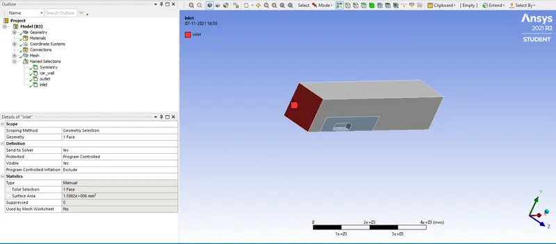
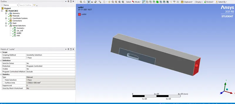
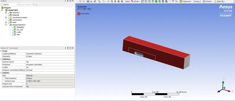
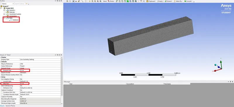
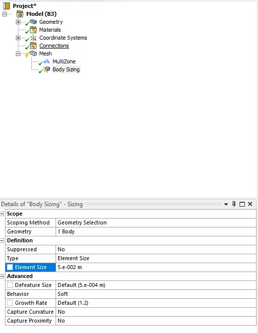
The computational mesh is created in mesh module of Ansys. Hexahedral mesh method is used for the outermost enclosure or box which represents the fluid domain. The basic mesh cell size is taken as 100 mm as shown below. Then the body sizing method is used for the local mesh refinement on the inner enclosure. And the mesh cell size is taken as 50 mm.
Boundary layer meshing
The boundary layer meshes are semi-structured grids grown from the surface. Most often in CFD analyses, they are used to solve high gradients of temperature or momentum normal to a surface. In general, Boundary layer meshes are useful where ever there strong gradient in the solution normal to surface.
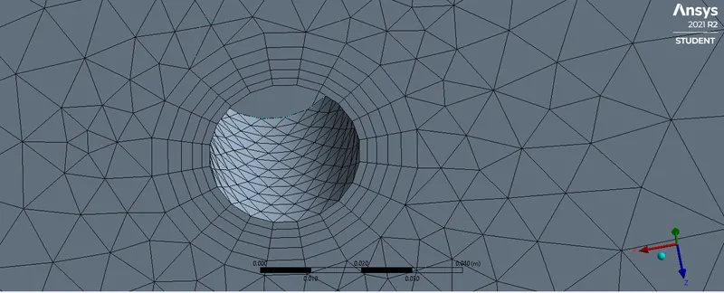
In our problem, the boundary layer meshes are introduced by creating the inflation layers as shown below. The total thickness is used in order to constrain the mesh is the right direction and set to a value of 12.5 mm for 5 layers having a growth rate of 1.2.
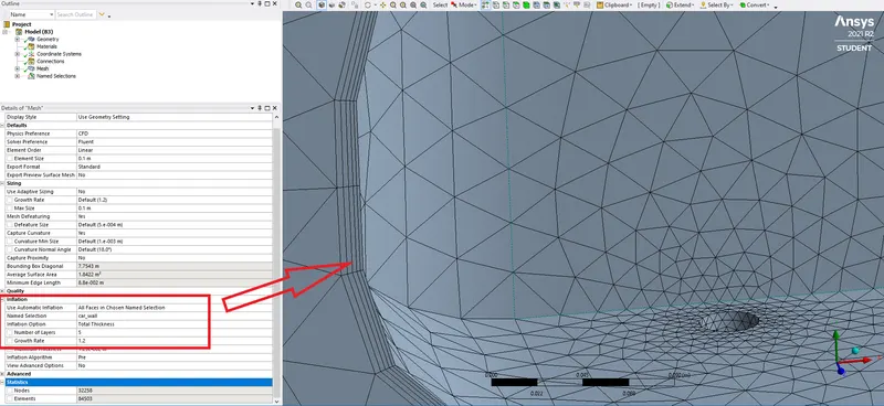
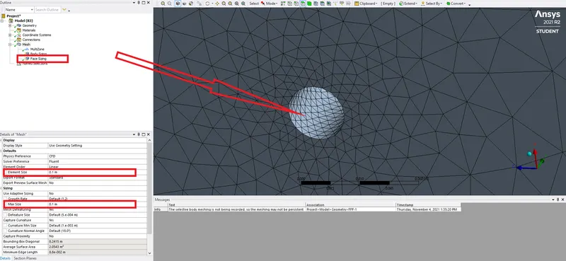
Moreover, the face sizing method is used to adjust the mesh according to the shape of the concerned surfaces as shown.
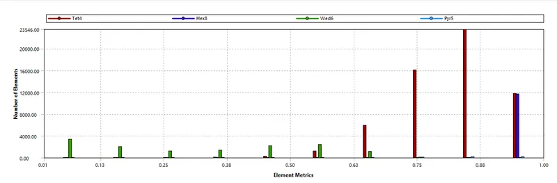
The minimum mesh quality is 6.21% which correspond to wedge mesh at some region of the domain.
Case setup
- The geometry used is that of Ahmed body as shown previously.
- The outmost enclosure’s dimensions are as follows: 1.5m in negative x-direction, 5 m in positive x-direction, 1 m in positive y-direction and negative z-direction. The remaining directions being 0. For the inner enclosure, the dimensions are as follows: 0.75 m in negative x-direction, 1.5 m in positive x-direction, 0.25 m in positive y-direction and negative z-direction. The remaining dimensions being 0.
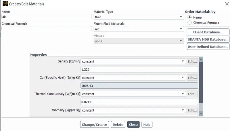
- The fluid used is Air () enters the computational domain through the inlet at u1=25m/s.
- Boundary conditions used:
-Velocity-inlet at the inlet
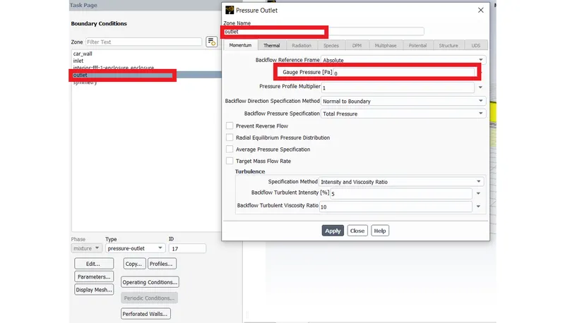
-Pressure-outlet at the outlet
-Symmetry for the enclosures faces
-Wall for the surface of the car
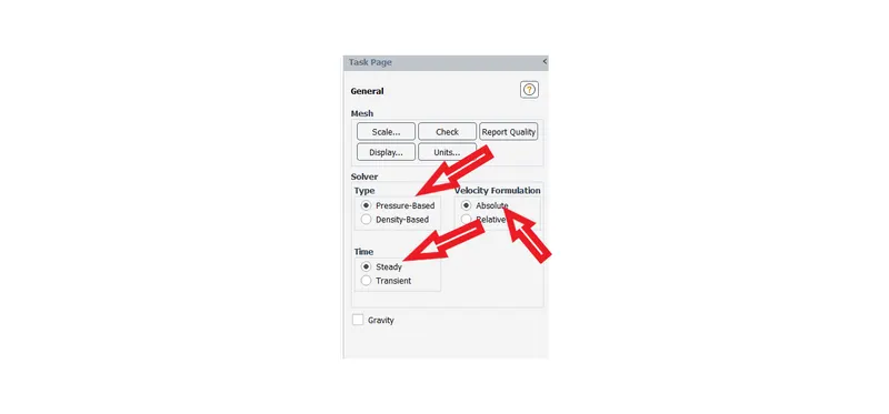
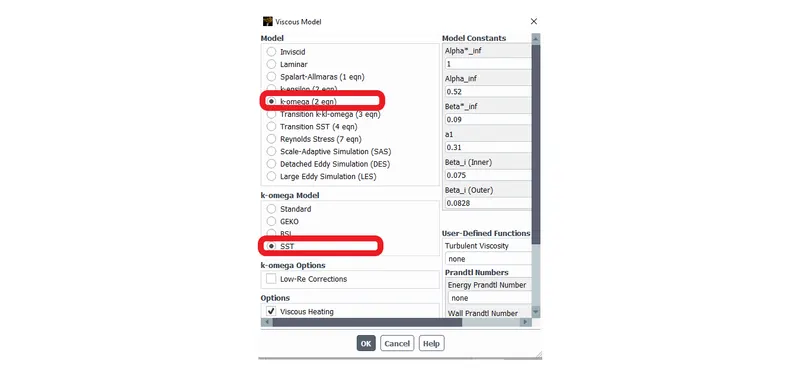
- Steady-state simulation is performed using Ansys Fluent with the pressure-based coupled solver since the compressibility effects are not considered.
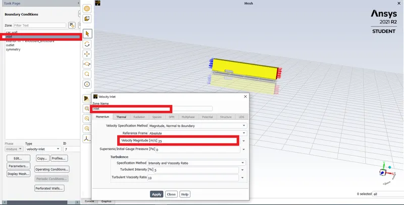
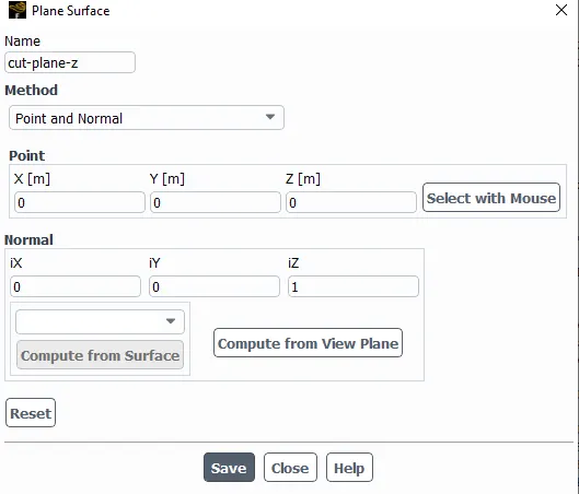
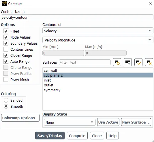
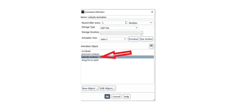
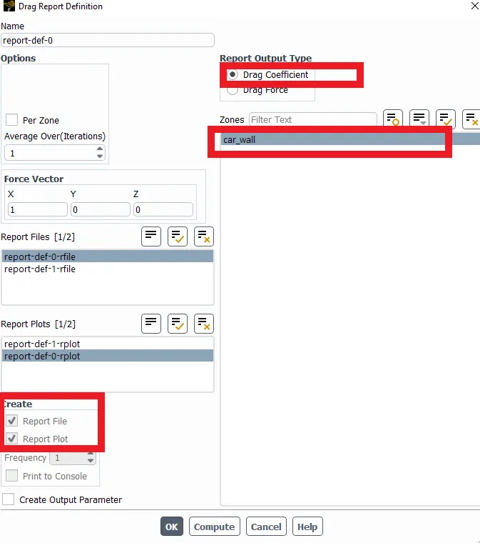
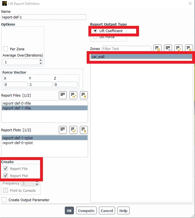
The report for drag and lift coefficients are defined as shown:
Post-processing
This part is about running the simulation in Fluent which enable the quantities such as drag coefficient, lift coefficient to be computed. These informations are stored in user defined reports.
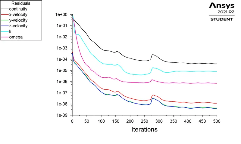
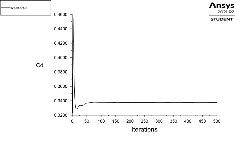
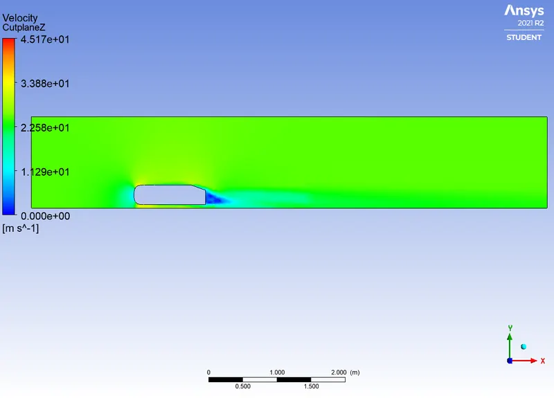
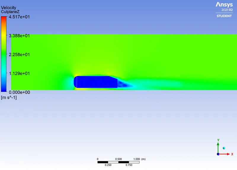
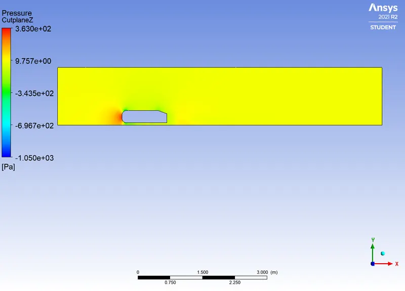
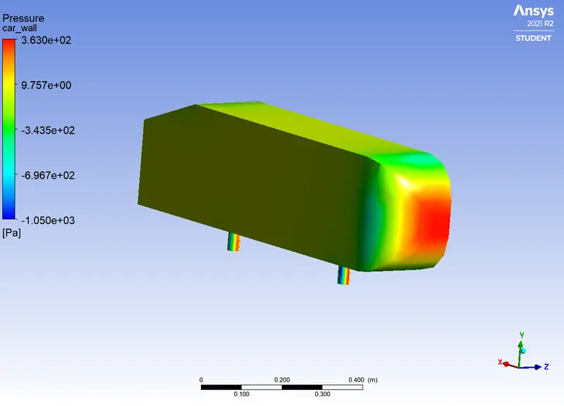
The value of drag coefficient is 0.33
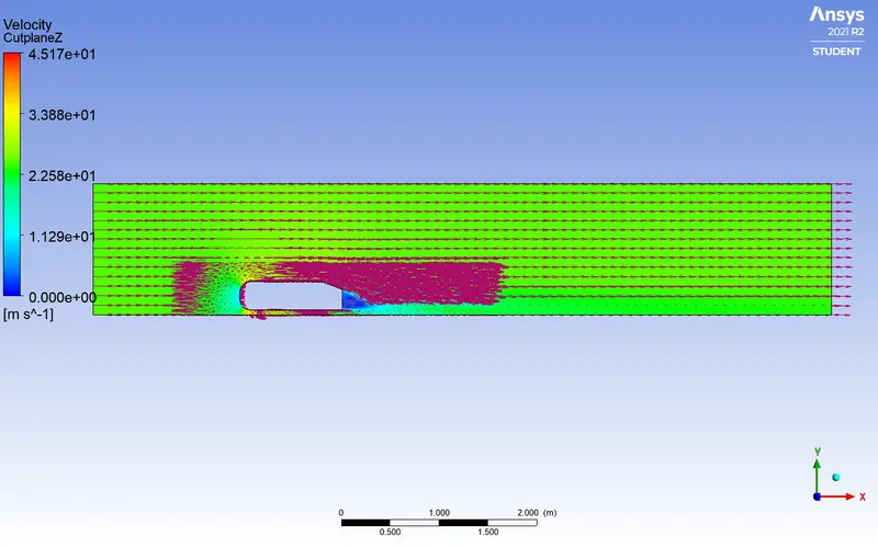
Negative Pressure Observed in Wake Region and point separation
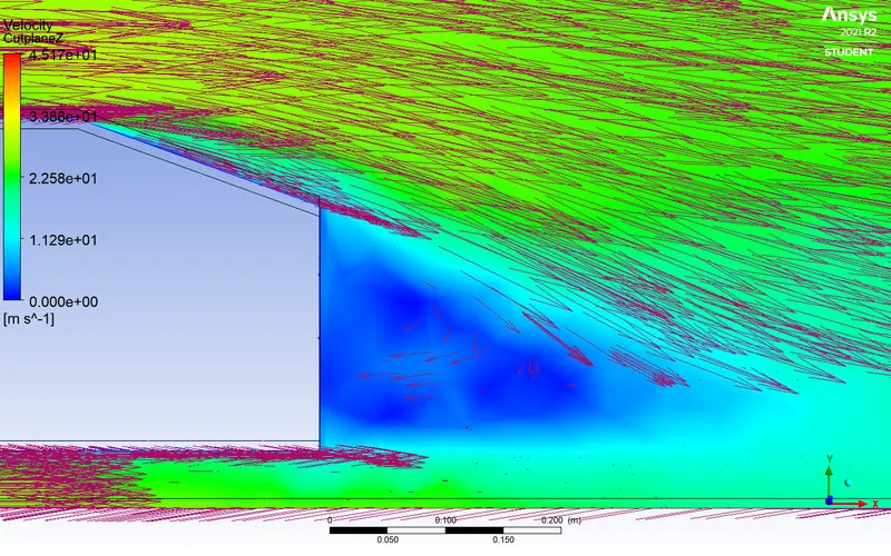
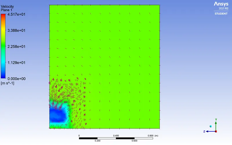
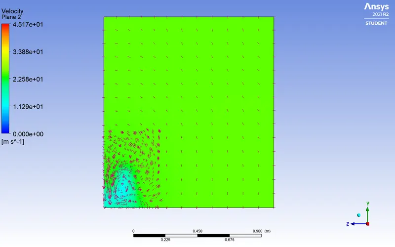
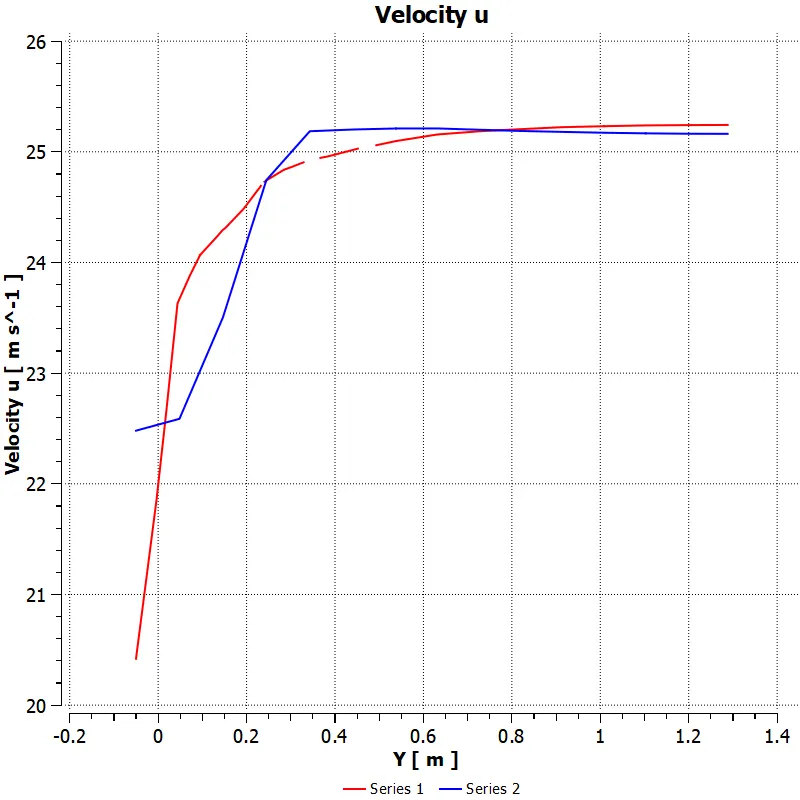
As it can be seen through the results, there is negative pressure in the wake region. The pressure is high at the front end of the Ahmed body and drop to negative values. We can notice that the flow once at the rear of the Ahmed body is detached from the body. This results in eddies formation making the flow unstable in that region called wake. The inlet velocity of 25m/s once in contact with the Ahmed body gets stagnated and starts decreasing. As a result, the pressure increases. The fluid gets separated from the body at its slant forming the point of separation.
According to boundary layer theory, the boundary layer will increase in our case since the velocity decreases. Due to this, the kinetic energy decreases. Since this loss in kinetic energy is being recovered from adjacent fluid layer through momentum exchange process, the velocity keeps decreasing. This happens until the point of separation is reached leading to the pressure drop in negative values. The reduction in pressure increases the vortices and eddies at the rear of the car inducing extra drag forces. Thus, it’s determined that the car should be designed is such a way that the point of separation occurs at a level which makes the negative pressure occur away from the boundary.
Grid Dependency test:
|
Case |
Outer Enclosure Mesh (mm) |
Inner Enclosure Mesh (mm) |
Face Sizing (mm) |
Number of Cells |
Drag Coefficient |
Lift Coefficient |
|
Grid 1 |
100 |
50 |
5 |
84503 |
0.33776362 |
0.20772678 |
|
Grid 2 |
100 |
40 |
4 |
130781 |
0.31538967
|
0.2090103 |
|
Grid 3 |
50 |
30 |
3 |
376384 |
0.29723445 |
0.21999657 |
Conclusion
The flow over Ahmed body is performed. Different contours are shown and the negative pressure in the wake region is explained. The vector plot is done showing the velocity behaviour in the wake region. Moreover, the grid independency test is carried out and drag coefficient and lift coefficient are computed. But it’s to be noticed that, apart from the local mesh refinement, the convergence of the solution also depends on the y+ value which is not much discussed in this problem.
References:
- https://www.researchgate.net/publication/266883948_Flow_and_Turbulence_Structures_in_the_Wake_of_a_Simplified_Car_Model_Ahmed_Model
- https://www.researchgate.net/publication/330383775_Experiments_and_numerical_simulations_on_the_aerodynamics_of_the_Ahmed_body
- https://byjusexamprep.com/concept-of-boundary-layer-and-its-growth-i-d633ef01-75b7-11e6-99b9-f5ba37a77793