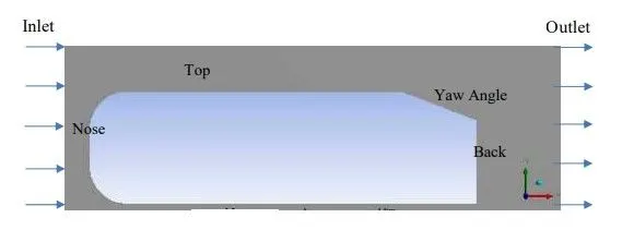
Week 3 - External flow simulation over an Ahmed body.
External flow simulation over an Ahmed body
Aim:-Able to simulate flow over Ahmed's body using Ansys Fluent.
Expected Results:
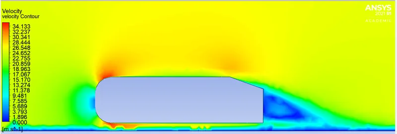
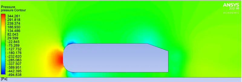
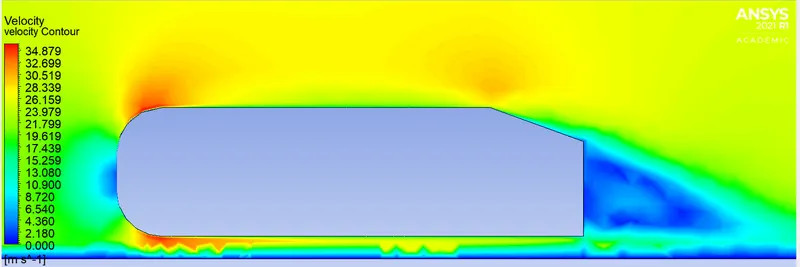
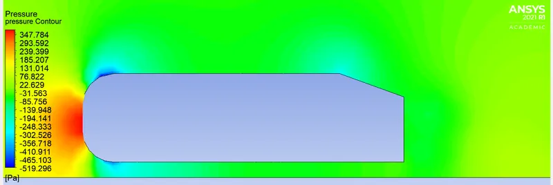
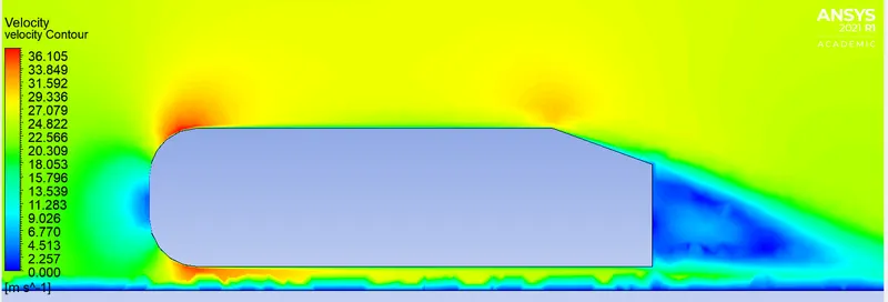
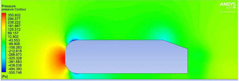
1. Velocity and pressure contours.
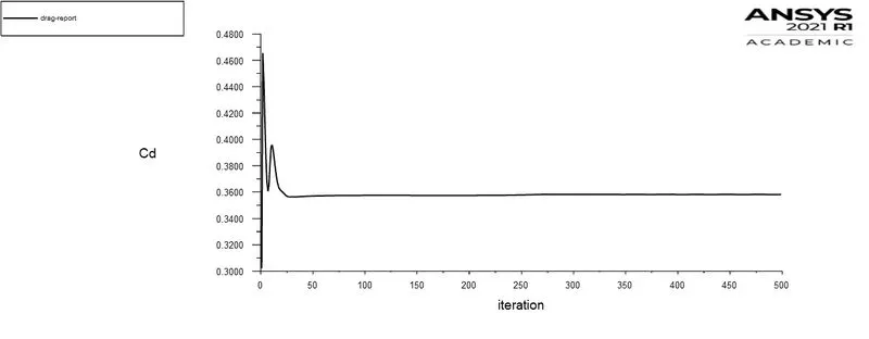
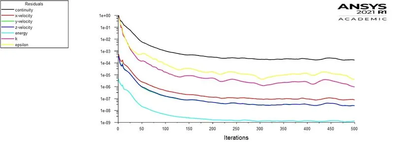
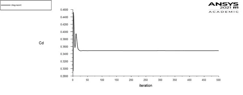
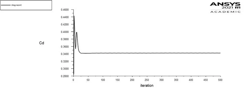
2. The drag coefficient plot for a refined case. ( For a velocity of 25m/sec, the drag coefficient should be around 0.33).
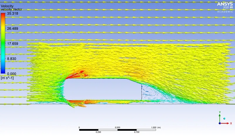
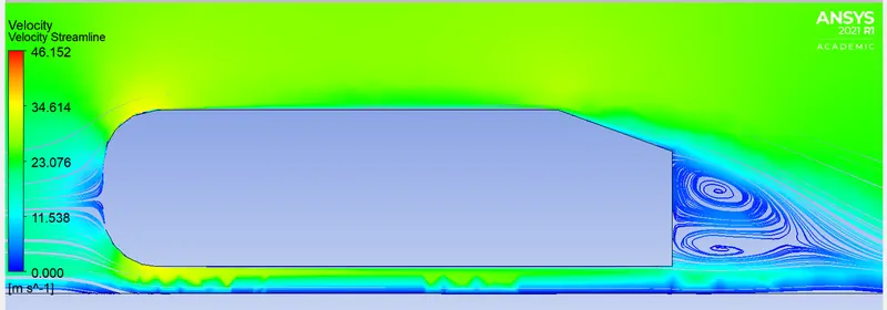
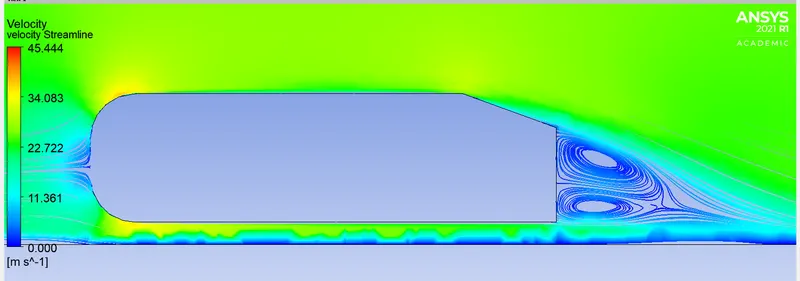
3. The vector plot clearly shows the wake region.
4. Perform the grid independence test and provide the values of drag and lift with each case.
1) Describe Ahmed's body and its importance.
The Ahmed body is a generic car body (a simplified vehicle model). The airflow around the Ahmed body captures the essential flow features around an automobile and was first defined and characterized in the experimental work of Ahmed. Although it has a very simple shape, Ahmed's body allows us to capture characteristic features that are relevant to bodies in the automobile industry.
This model is also used to describe the turbulent flow field around a car-like geometry. Once the numerical model is invalidated, it is used to design new models of the car.
Ahmed's body is considered to be the benchmark for the automotive industry that is used to determine the drag around the region of the body. There are lots of experimental results that are obtained through different methods.
Ahmed body simulation mainly used to validate the numerical results produced from numerical models with the experimental data from wind tunnel testing is available for Ahmed's body.
This analysis is used to find Velocity & Pressure profile, Aerodynamic Drag & Lift force's, Vector profiles.
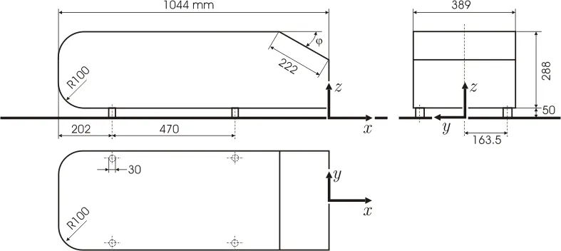
Depending on the `phi` value we can observe three main features:
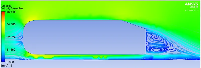
1. The A recirculation region that is formed as the flow separates at the top of the vertical back surface of the model
2. The B recirculation region is formed due to the separation at the base of the model.
3. The c-pillar vortices that form as the vorticity in the side boundary layers roll up over the slant edges.
The wake was shown to be highly dependent on slant angle. For slant angles less than 12°, the flow remains attached over the slant. The flow is essentially two-dimensional and has low drag. Between 12° and 30°, the flow becomes much more three-dimensional as the c-pillar vortices form. These reach maximum strength at 30°. The drag increases significantly as the low-pressure cores act on the rear surfaces. Past 30° the flow separates fully off the slant. This results in a sudden decrease in drag and weaker c-pillar vortices.
Procedure:
- Geometry
- Meshing
- Setup
- Solution
- Results
Open Ansys Workbench and create Fluid Floe(Fluent) as a Standalone system.
Geometry:-
- Open SpaceClaim for creating Geometry.
- Import Ahmed body geometry into SpaceClaim.
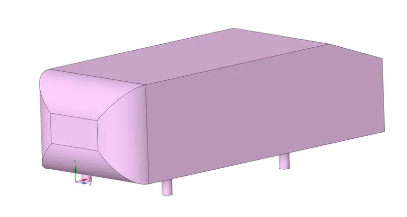
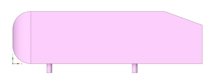
- Create an enclosure around Ahmed's body which acts as a computational domain.
- Make sure to use multiple enclosures around the body in this problem I used 2 enclosures. This helps the user to refine the mesh near the body to capture results accurately with less computation time.
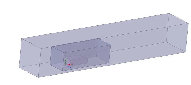
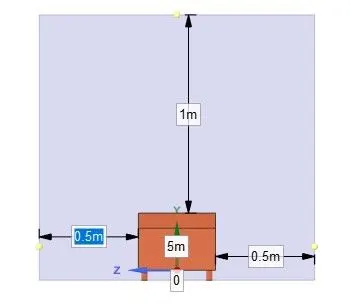
- 1st one is an Outer enclosure with a size of 1.389* 1.338*8.044 meters.

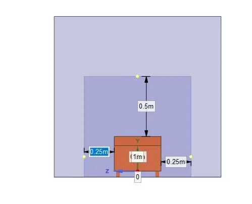
- 2nd one is an Inner encloser with a size of 0.889*0.838*2.544 meters.
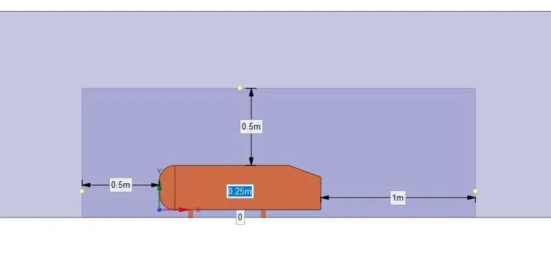
- Make sure that for both these enclosures Share Tropology = Share
- Check for the interference between bodies by using section mode. If you find any interference delete the interference body.
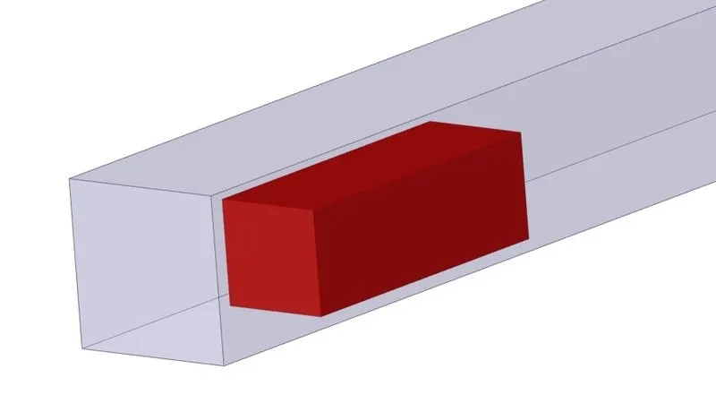
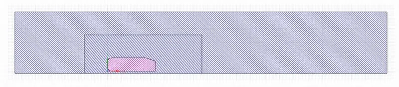
- Finally, Suppress the Ahmed body for Physis because we don't want our equations to be solved in the Ahmed body region.
2. Meshing:-
- Create Named Sections (Inlet, Outlet, Car wall, Outer Symmetry)
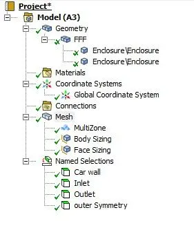
- Meshing is done by four methods
- Insert => Method => Geometry = Outer enclouser => method = Miltizone => Type = Hexa
- Insert => Body Sizing => Geometry = Inner enclouser => Type = Element size
- Insert => Face Sizing => Geometry = Carwall => Type = Element size => size = 5mm.
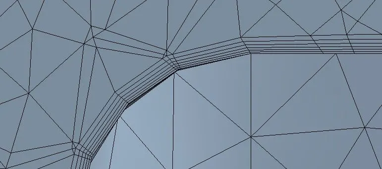
- Inflation => Section = Carwall => Option = Total thickness => N layers = 6 => Growth rate = 1.2 => Maximum Thickess = 12.442 mm.
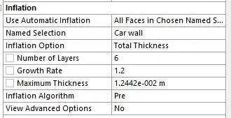
- `text(Total thickness ) = text(First layer thickness )* (text(Growth rate) ^(text(Number of layers) - 1)) = 5*(1.2^(6-1))=12.4416 mm`
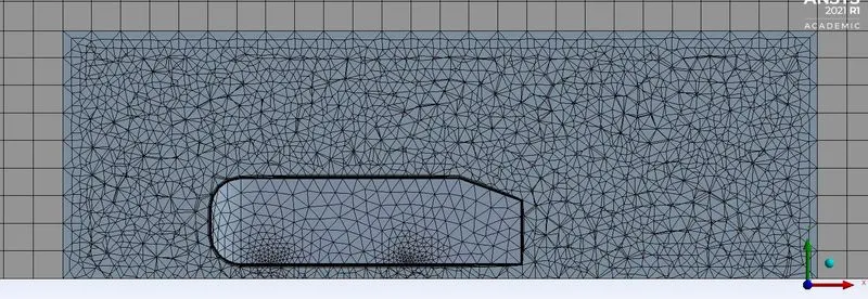
- For the Grid independence study, we are using different combinations for the size of the outer and inner enclosure. But, there is no change in car wall size and inflation layers.
-
Max element size of
Outer Enclosure (mm)
Max element size of
Inner Enclosure (mm)
Number of Nodes Number Of Elements Case - 1 100 50 57594 179848 Case - 2 90 45 72325 228728 Case - 3 80 40 92398 299820 Case - 4 70 35 125169 418903
-

3 & 4. SetUp & Solution:-
- Double Presission, Solve processers = 4.
- `text(fluid velocity )/text(Sound velocity) = 25/343 = 0.07 < 0.3 text( Mach number) = text(Pressure based solver)`
- Solver = Pressure Based, Velocity Formulation = Absolute, Time= Steady
- Energy = on
- Viscous Model = k-epsilon, Standard, Standard Wall function.
- Material => Default air from Fluent database.
- Cell zone conditions = Fluid
- Boundary Conditions
- Inlet => Velovity Inlet = 25m/s
- Outlet => Pressure outlet = 0 gauge
- Carwall => Standard, No slip.
- outer symmetry = symmetry
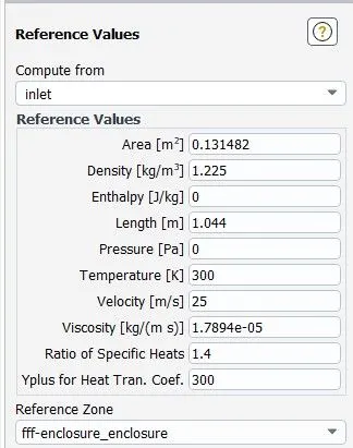
- Reference Values
- Methods => Coupled Pressure velocity scheme.
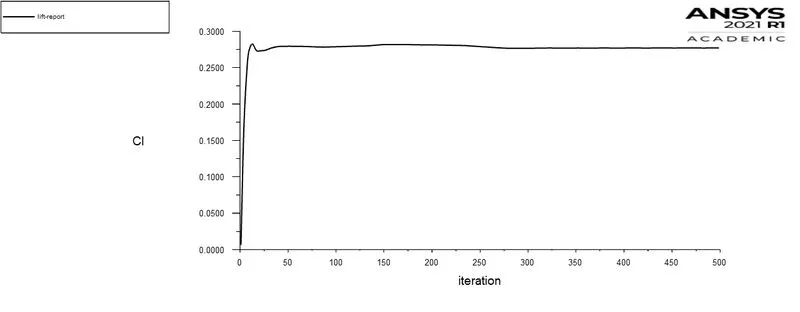
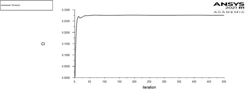
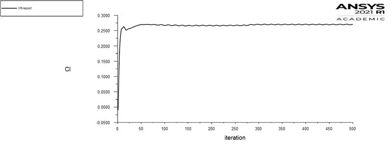
- Create Drag and lift coefficient reports over the Car wall
- Hybrid initialization
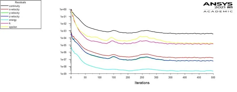
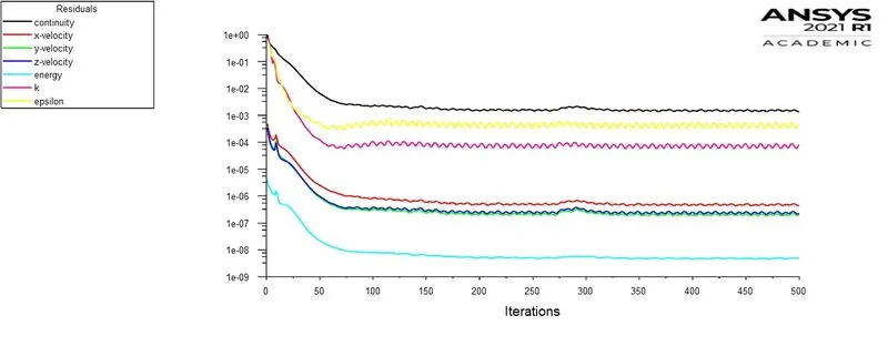
- Uncheck the convergence & Run calculation for 500 iterations for each case.
Results:-
- Create Z plane and plot velocity, pressure contours on the z plane.
- Create velocity vectors and streamlines on the Z plane.
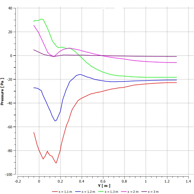
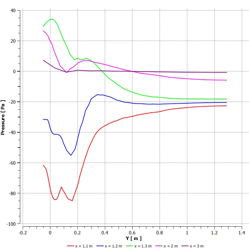
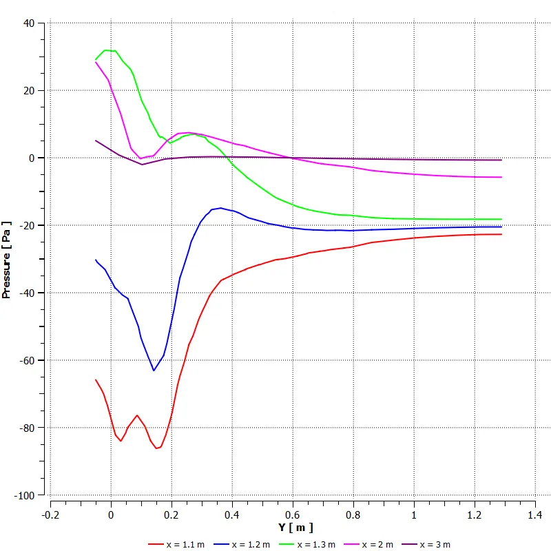
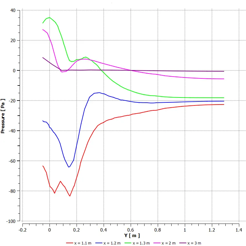
- Create y-z plane and y lines on x-axis at distances x = 1.1,1.2,1.3,2,3 meters
- Plat velocity vectors and contours on those XY planes.
- create pressure chat using y lines
Case 1:
Max element size of Outer Enclosure = 100 mm ; Max element size of inner Enclosure = 50 mm ;
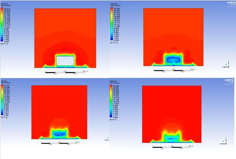
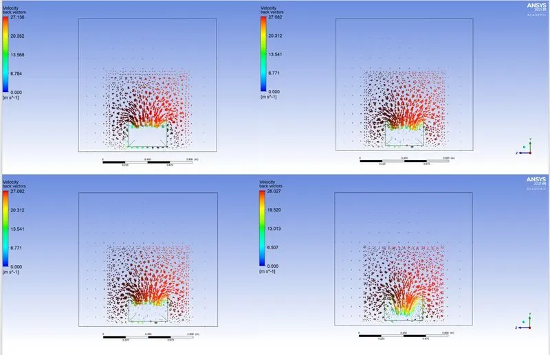
Case 2:
Max element size of Outer Enclosure = 90 mm ; Max element size of inner Enclosure = 45 mm ;
Case 3:
Max element size of Outer Enclosure = 80 mm ; Max element size of inner Enclosure = 40 mm ;
Case 4:
Max element size of Outer Enclosure = 70 mm ; Max element size of inner Enclosure = 35 mm ;
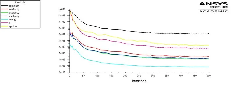
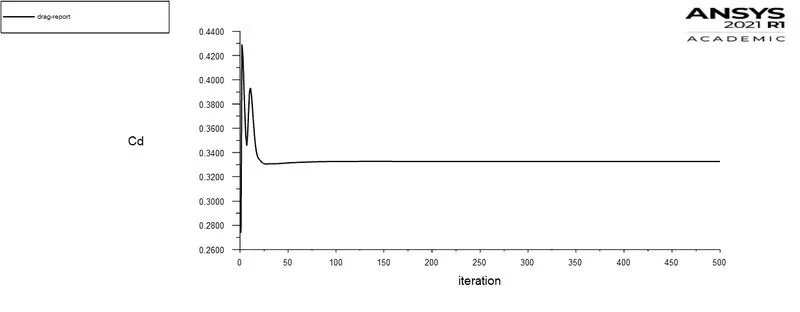
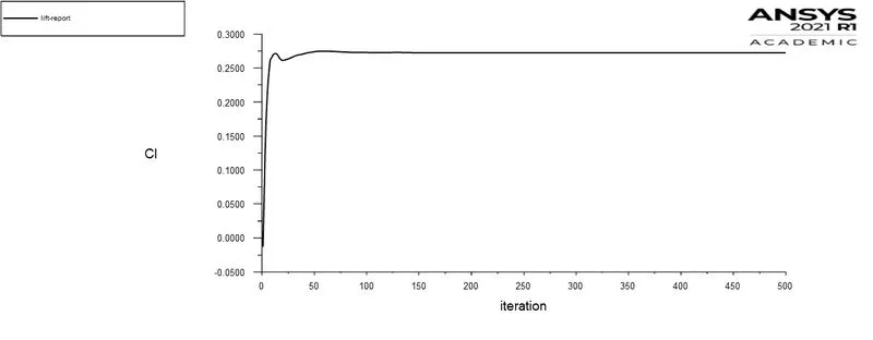
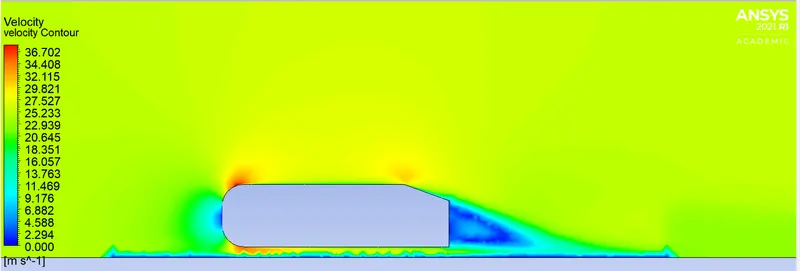
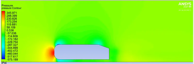
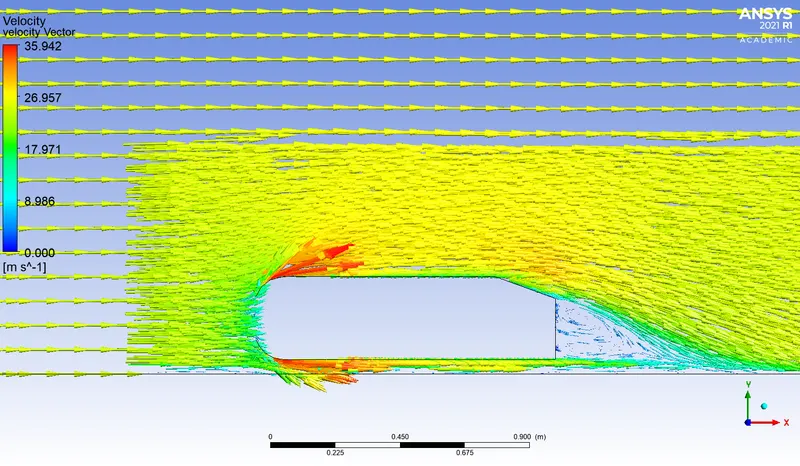
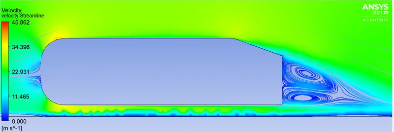
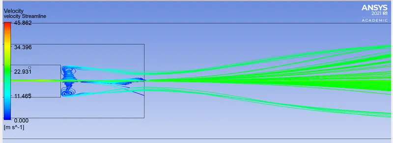
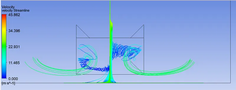
Results:-
|
Max element size of Outer Enclosure (mm) |
Max element size of Inner Enclosure (mm) |
Drag Coefficient | Lift Coefficient | |
| Case - 1 | 100 | 50 | 0.35818 | 0.27695 |
| Case - 2 | 90 | 45 | 0.34855 | 0.27535 |
| Case - 3 | 80 | 40 | 0.34217 | 0.27071 |
| Case - 4 | 70 | 35 | 0.33260 | 0.27223 |
As the mesh gets refined from case 1 to 4 drag coefficient value also becomes smooth reaches the exact solution of 0.33.
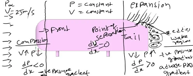
wake Region
Region of recirculating flow or formation of vortex immediately behind a moving or stationary blunt body, caused by viscosity which may be accompanied by flow separation and turbulence.
Explain the reason for the negative pressure in the wake region.