Week 3 - External flow simulation over an Ahmed body.
Aim:
To perform external flow simulation over an Ahmed body and to find the drag coefficient for an air velocity of 25m/s
Introduction:
Importance of Ahmed body:
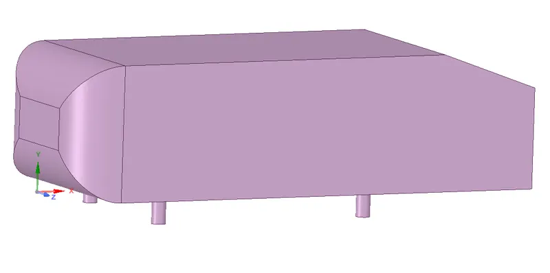
An Ahmed body is a benchmark model widely used in the automotive industry for validating simulation tools. It was first proposed by Ahmed and Ramm in 1984. It is very useful because it can be used to study the geometric effects on automobiles. The main objective in designing a car model is to increase its performance by reducing drag. If the drag is reduced then the fuel consumption is also less reduced. Hence the Ahmed body acts as an important and helpful tool in the automotive industry.
Theory:
Drag coefficient:
It is a dimensionless quantity that is used to quantify the resistance of an object in a fluid environment, such as air or water. It is given by :
`C_d=(2F_d)/(rhou^2A)`
where,
`F_d` is the drag force
`rho` is the density of the fluid
u is the flow speed
A is the area
Wake region:
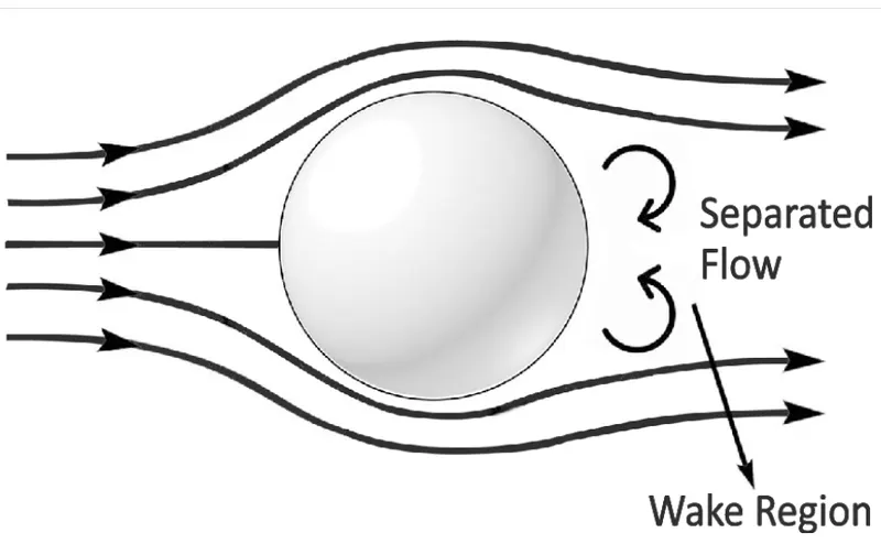
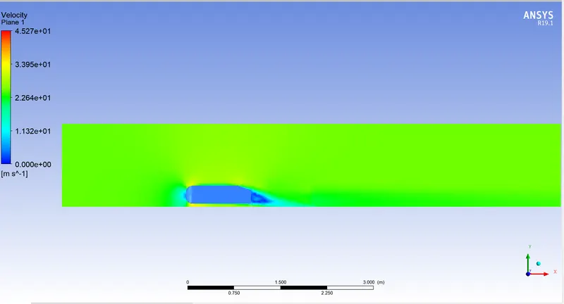
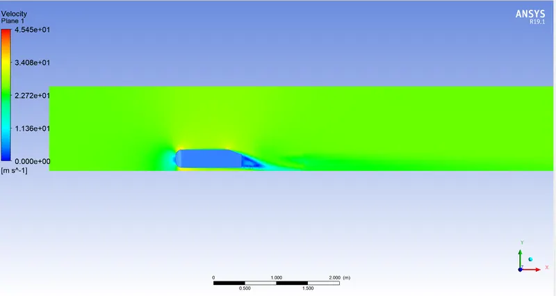
It is a region of recirculating flow behind a body caused due to flow separation, turbulence, and viscosity of the fluid
Pre-processing:
Geometry
At first, we create an enclosure around the Ahmed body and suppress the body for physics, this gives us a good baseline model to perform simulation, but still, there are some things needed to be changed to get accurate solutions
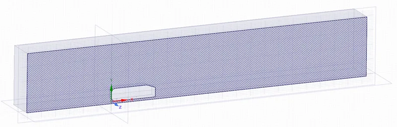
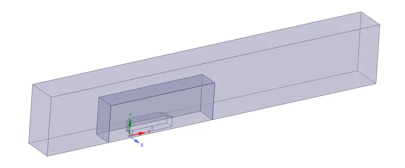
Now we create another enclosure to get more precise values in the wake region and run to interference test to avoid overlapping of mesh

Then using the split body command the geometry is cut in half
Meshing
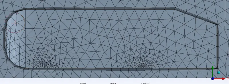
Initial mesh
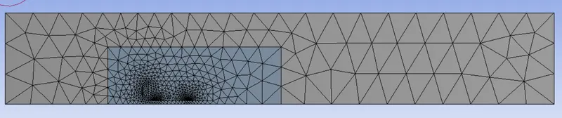
We add a multizone method to apply Hexa mesh with a size of 0.1m wherever possible
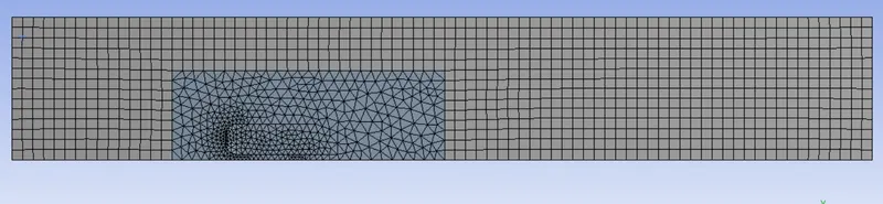
We add sizing to the inside enclosure with a size of 0.05m
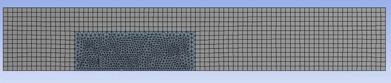
Then we add face sizing for the support of the Ahmed body to get a perfect circle shape, size was given as 0.005 m
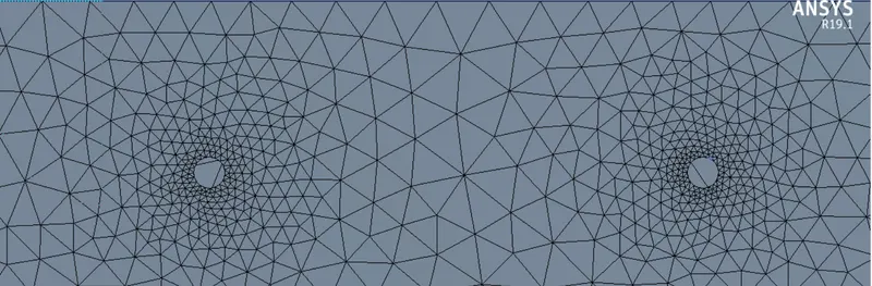
Adding inflation region around the Ahmed body walls with a total thickness of 0.0124 m
Setup:
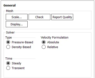
A pressure-based solver is chosen and the k-epsilon turbulence model is used
Steady-state simulation
The material used is air with default properties in fluent
Boundary conditions:
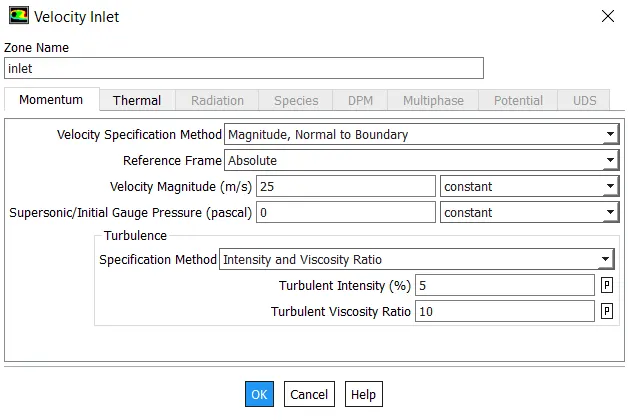
- inlet velocity - 25m/s
- Outlet pressure - 0
- Symmetry wall - symmetry
- car walls - no slip
Result:
Case 1 :
Mesh size - 0.1 m outside
Mesh size - 0.05 m inside
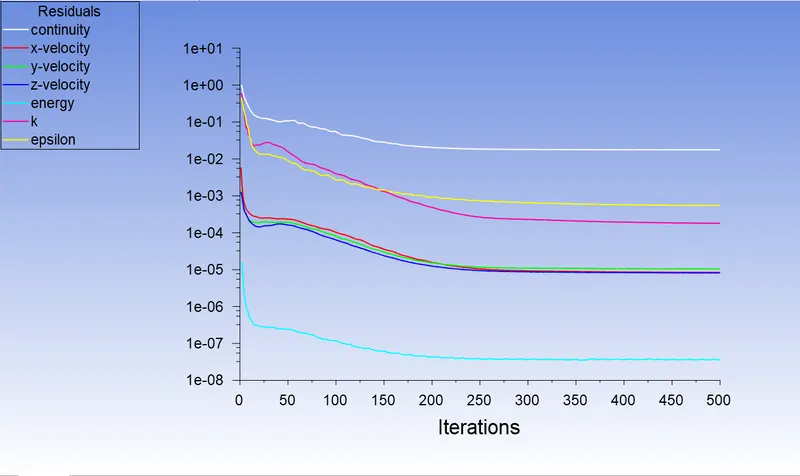
Residual plot:
Velocity contour:
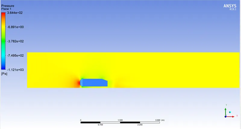
Pressure contour:
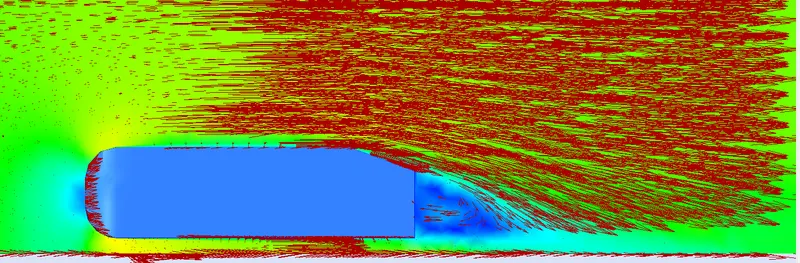
Vector plot:
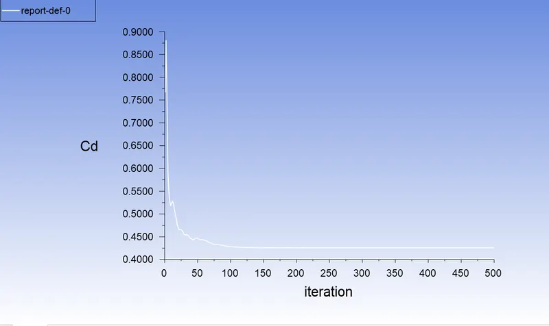
Drag coefficient plot:
Lift coefficient plot:
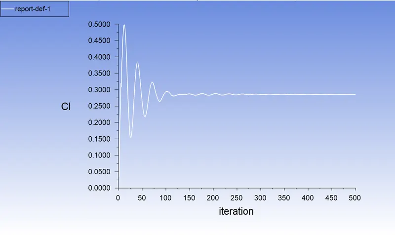
Case 2 :
Mesh size - 0.09 m outside
Mesh size - 0.04 m inside
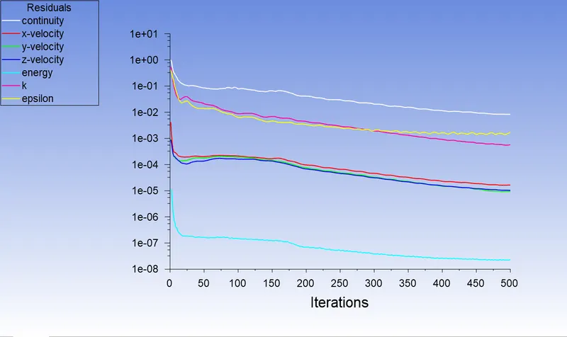
Residual plot:
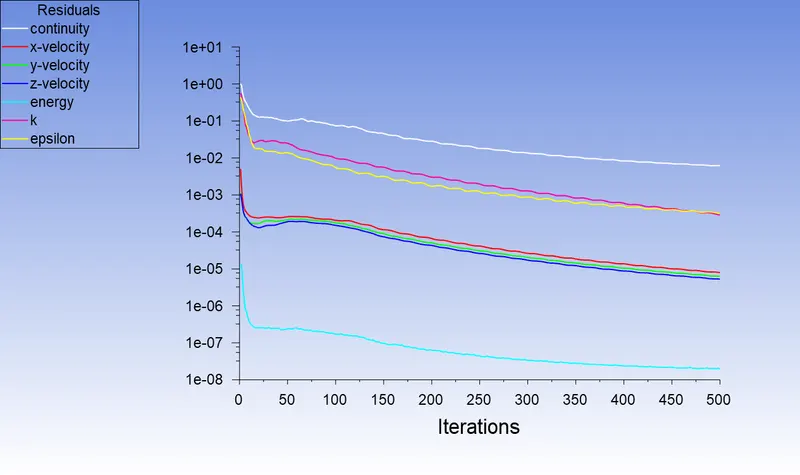
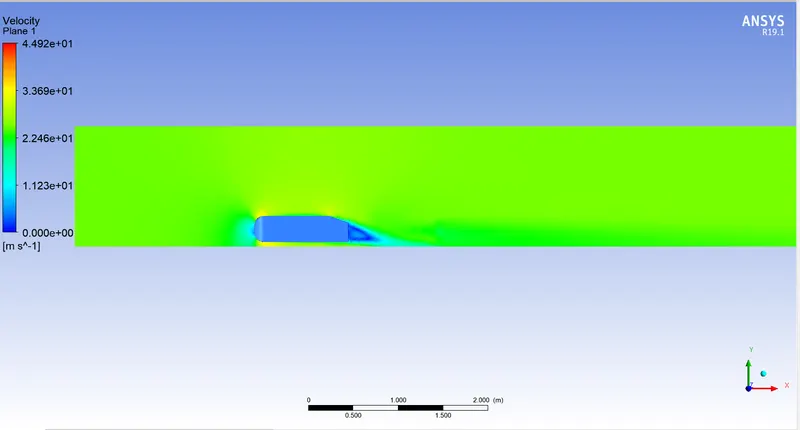
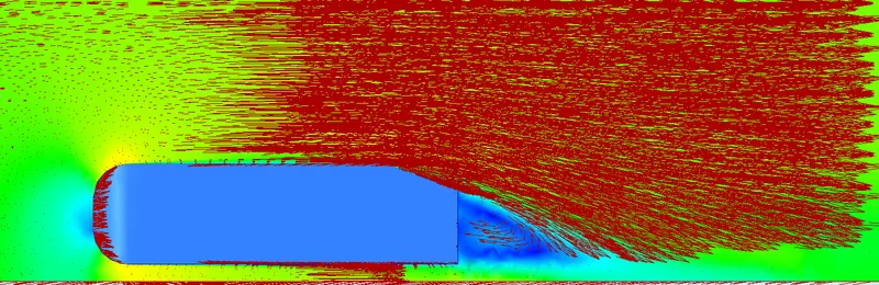
Velocity contour:
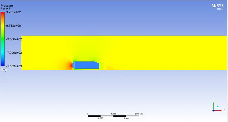
Pressure contour:
Vector plot:
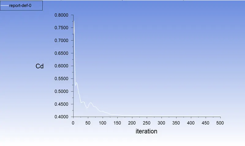
Drag coefficient plot:
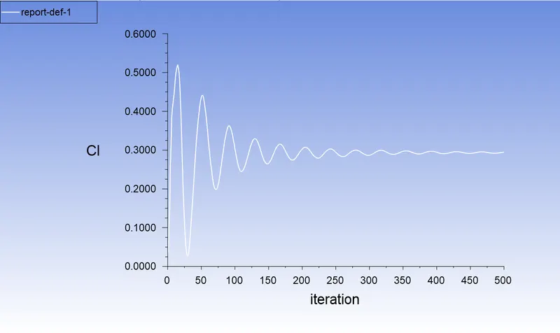
Lift coefficient plot:
Case 3 :
Mesh size - 0.08 m outside
Mesh size - 0.03 m inside
Residual plot:
Velocity contour:
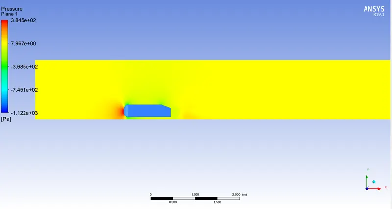
Pressure contour:
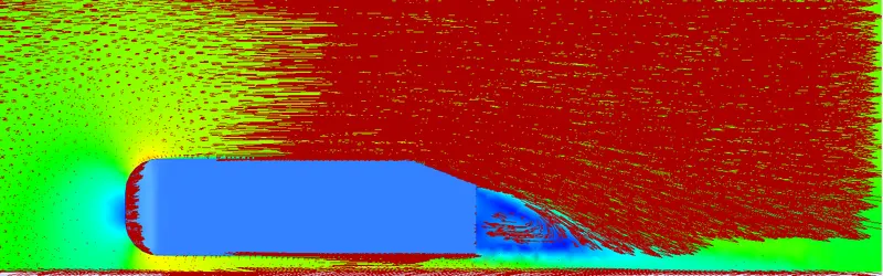
Vector plot:
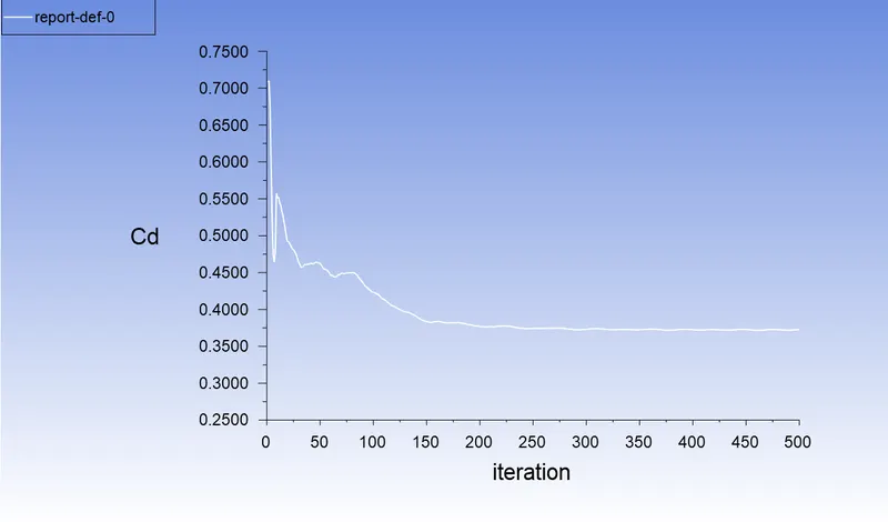
Drag coefficient plot:
Lift coefficient plot:
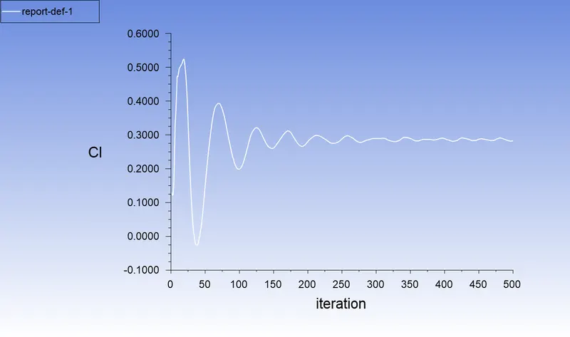
Case 4 :
Mesh size - 0.07 m outside
Mesh size - 0.02 m inside
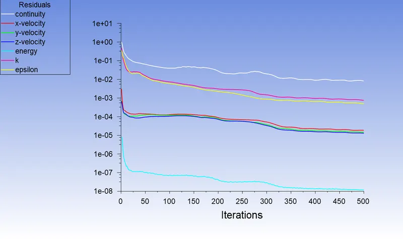
Residual plot:
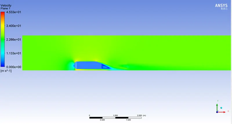
Velocity contour:
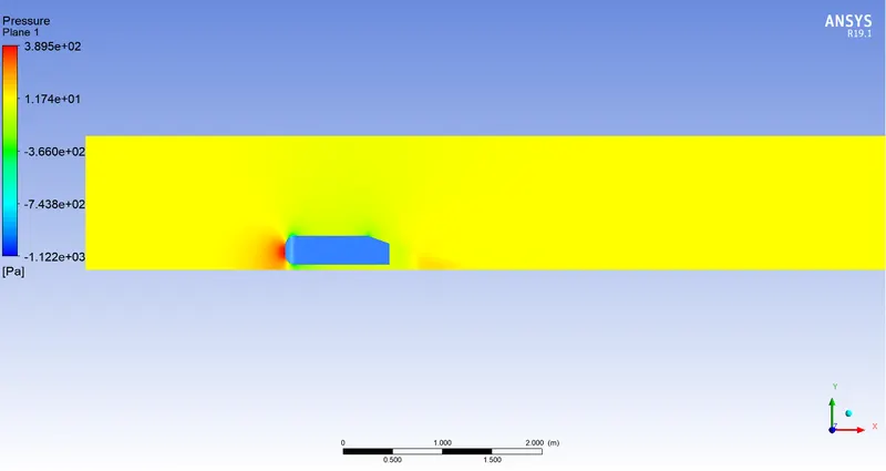
Pressure contour:
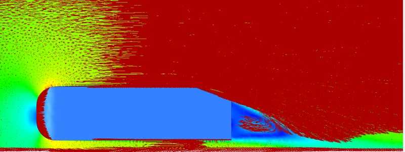
Vector plot:
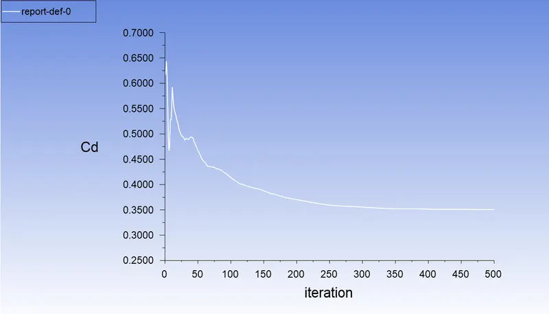
Drag coefficient plot:
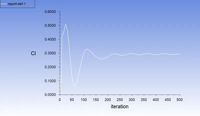
Lift coefficient plot:
Grid Independence
| No. of elements | Outside enclosure size | Inside enclosure size | Drag coefficient | Lift Coefficient |
| 96418 | 0.1 m | 0.05 m | 0.43 | 0.27 |
| 152971 | 0.09 m | 0.04 m | 0.4 | 0.28 |
| 302568 | 0.08 m | 0.03 m | 0.37 | 0.29 |
| 919821 | 0.07 m | 0.02 m | 0.35 | 0.295 |
Conclusion:
Reason for negative pressure in the wake region:
So when the velocity increases pressure will decrease and at the rear end of the Ahmed body, the flow is getting separated which causes low pressure in that region. The vortices formed in the wake region are also a major factor for the negative pressure because of the recirculation of flow.
Significance of flow separation:
If the flow separation is delayed then the drag forces can be reduced, this is due to the fact that the wake region will be small at these conditions. Hence a reduction in drag force can reduce fuel consumption also, Therefore flow separation is very important in the simulation of automobiles. we can also reduce the wake region by increasing the slant angle.