DROP TEST SIMULATION ON A MOBILE PHONE BY USING LS DYNA & LS PREPOST
Aim:
- To create a complete simulation from a basic (.k) file having just primary datas like nodes and elements of two parts, a simplified mobile phone, and a bottom plate at the ground.
- Add the keyword to create a basic solver deck to simulate a drop test.
Procedure:
1. Open the Drop_Test_onlymesh.k file in LS-PrePost.
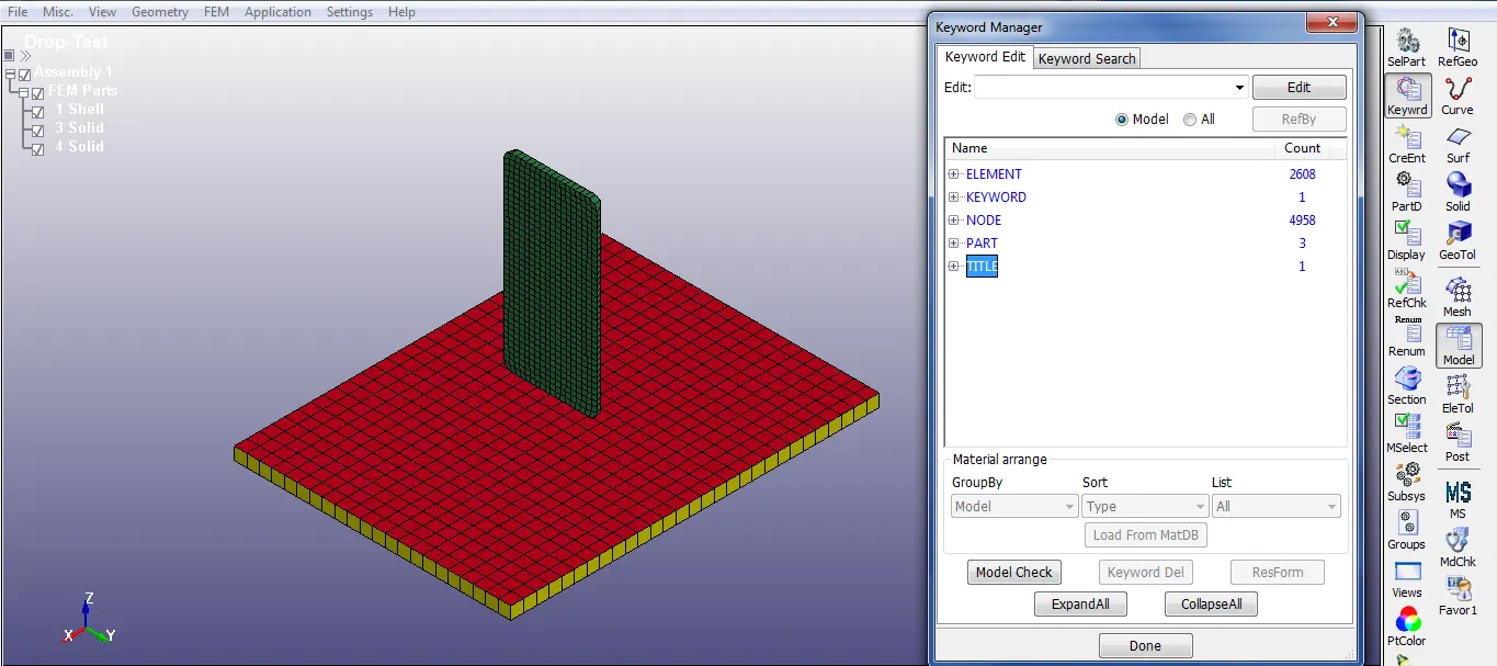
2. The opened file contains three parts, elements, nodes, keywords, and title. The parts consist of a bottom plate of shell elements and solid elements, the mobile phone of solid elements. Since the bottom plate given in both shell and solid, here we can do with solid elements.
Delete the red color shell elements (2D) using the Model and Part > Keyword Manager > Part > Element >Select the part > Click on Delete and Done
3. Define the material for both the bottom plate and mobile phone. Select the 020-MAT_RIGID material card to define the bottom plate and 024-PIECEWISE_LINEAR_PLASTICITY material card for the mobile phone.
Model and Part > Keyword Manager > MAT > Select the Material card
Next, define the material properties like mass density, Young’s modulus, Poisson’s ration, Yield point stress value, and other required quantities for both the material cards.
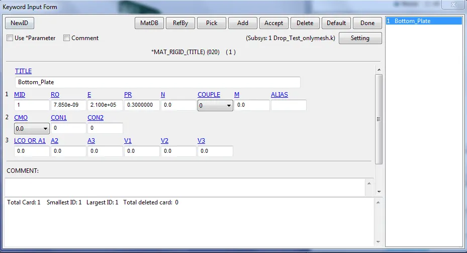
Fig: 020-MAT_RIGID material card
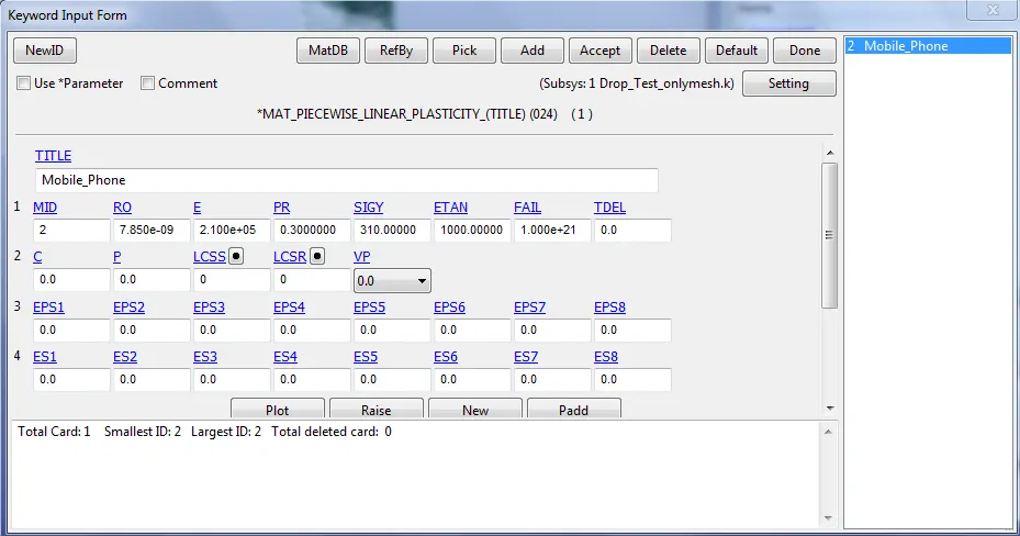
Fig: 024-PIECEWISE_LINEAR_PLASTICITY material card
4. Create a Solid section using the Model and Part > Keyword Manager > SECTION > Select the Solid option with Element formulation=1.
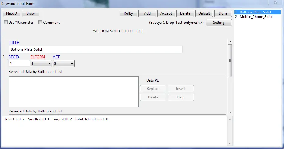
Fig: Defining Solid Section card
5. Specifying the respective Material and Section ID to the bottom plate and Mobile phone part IDs.
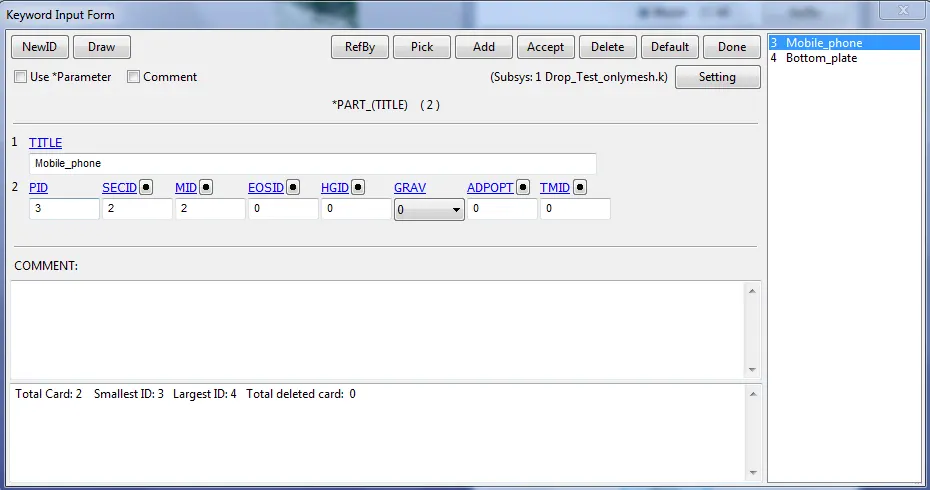
Fig: Specifying the Material and Section ID to the respective part IDs.
6. Assigning boundary conditions to the part is the next task. Here we need to create an entity under Boundary>Spc (Single point constraint), the bottom plate is to be fixed by constraining the boundary elements of it in all directions. The selection can be done by area for selection and along the edge and select the propagate selection for selecting the nodes of a straight edge in a single shot.
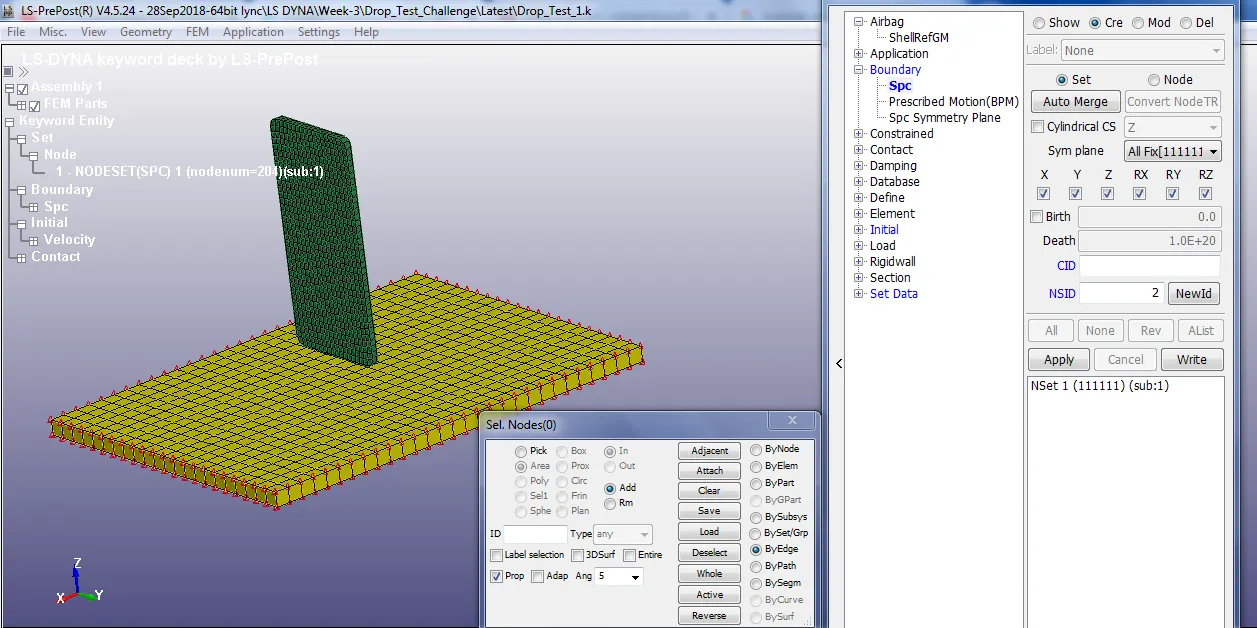
Fig: The bottom plate is fixed by constraining the boundary elements
7. Similarly, the velocity of 10000 mm/s (10 m/s) is given by creating an entity under Initial>Velocity. The mobile phone is selected by pick option with respect to part as shown below.
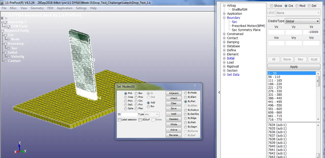
Fig: Freely falling Velocity boundary condition assigned for mobile phone
8. Create a Contact using Model and Part > Keyword Manager > Contact > Automatic Surface to Surface. The slave segment type (SSTYP) and master segment type (MSTYP) is defined by the Part IDs, select the Mobile phone part as a slave and the Bottom plate as Master
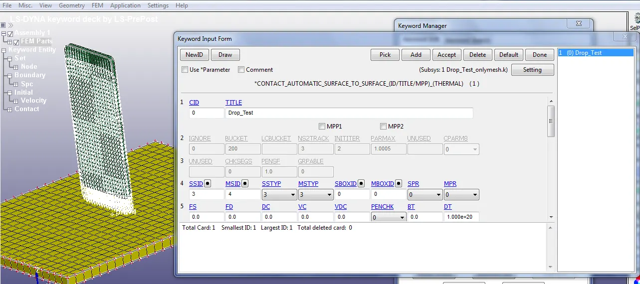
Fig: *CONTACT_AUTOMATIC_SURFACE_TO_SURFACE card defined for two-part ids
9. Set Model and Part > Keyword Manager >Control> Termination to 0.003 s (3 ms). By calculating the distance between the contact point of the two-part id we can able to find out the time required for the test to happen
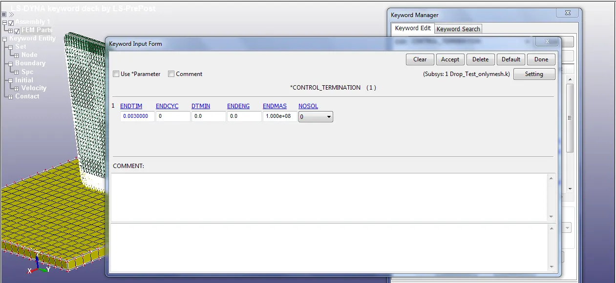
Fig: Termination time defined by using *CONTROL_TERMINATION card
10. To get the result out of the problem we need to carry on the following steps:
Model and Part > Keyword Manager > Database > ASCII select GLSTAT, RCFORC with DT 0.0001
Note: GLSTAT card is enabled with 0.0001 output time interval which gives global energy data like Kinetic Energy, Internal Energy, and other types of energy
RCFORC card is enabled with 0.0001 output time interval which gives forces due to contact between two parts mobile phone and bottom plate.
Model and Part > Keyword Manager > Database > Binary D3plot >DT 0.0001.
Note: This D3PLOT card gives animation and other post-processing data after the simulation
11. Save the Active Keyword and Runs in LS-DYNA Manager.

12. Binary Output Results:
After running successfully in the solver, open the binary d3plot file in LS-PrePost, and to play the animation file to view the Drop Test problem.
The following figures show the effective stress contours after the initial impact at say 21st frame (t=0.0019996 s) in the animation of the Drop test problem. Here from the figure(a), we can able to see higher stress values in the lower part of the mobile phone just after the impact because this is the very first region which interacts with the bottom plate and after this, we can able to see from the figure(b) & figure(c) stress propagates throughout the mobile phone due to a shock after the impact at the rigid plate at the bottom.
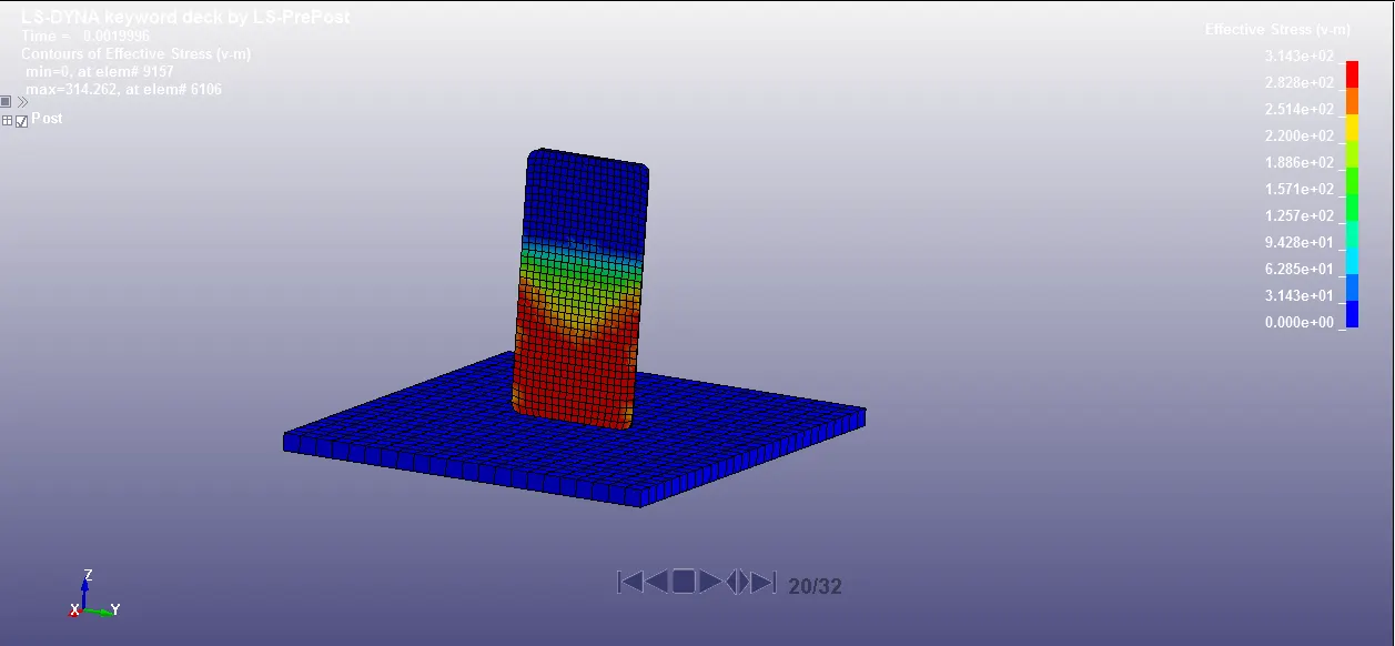 Fig: (a)
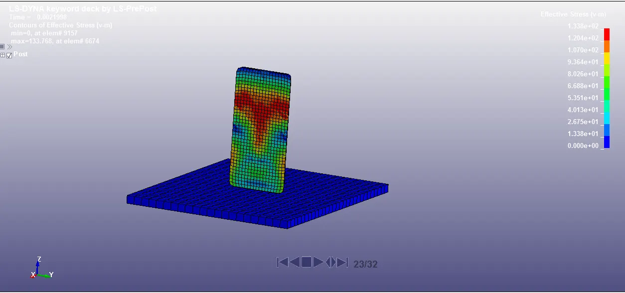 Fig: (b)
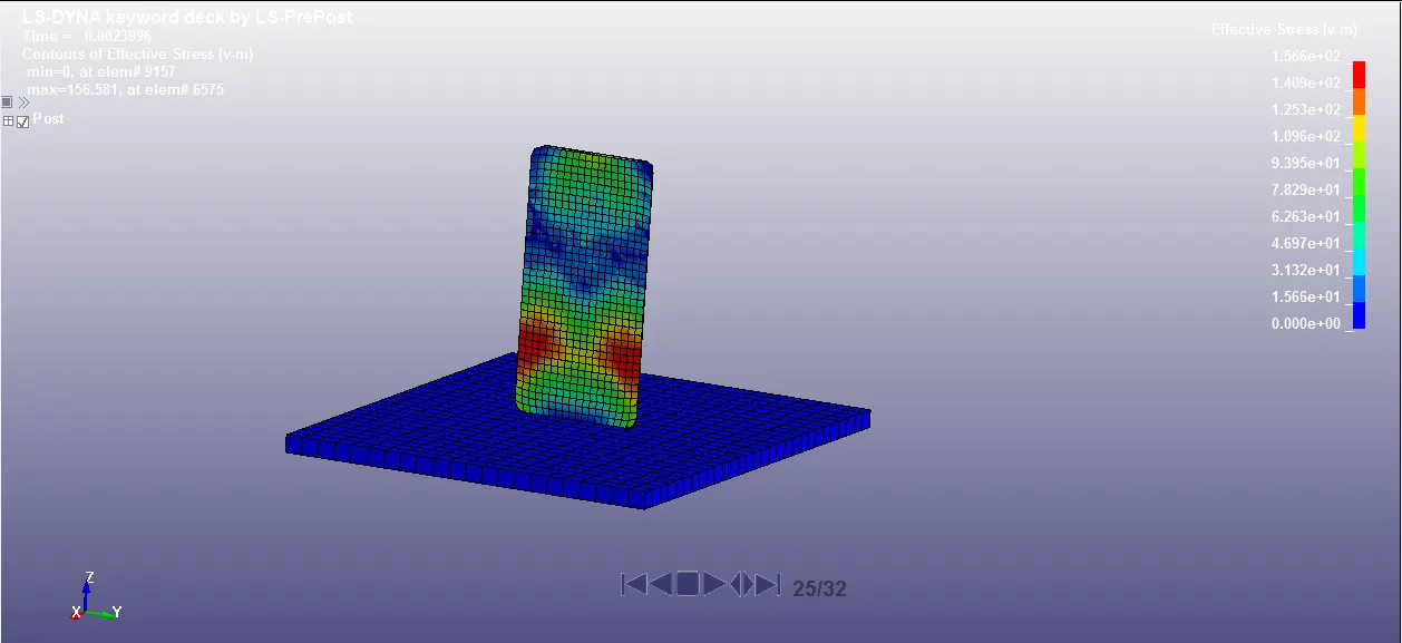 Fig: (c)
ASCII Output Results
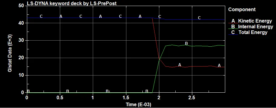
Fig: Kinetic, Internal, Total Energy vs Time plot
Initially, the mobile phone is having certain kinetic energy ie, ((1/2)mv^2), and when it impacted with the bottom plate the kinetic energy of the mobile phone drops down and at the same time, the internal energy is gained by the mobile phone due to the impact. The Total Energy of the component remains constant.
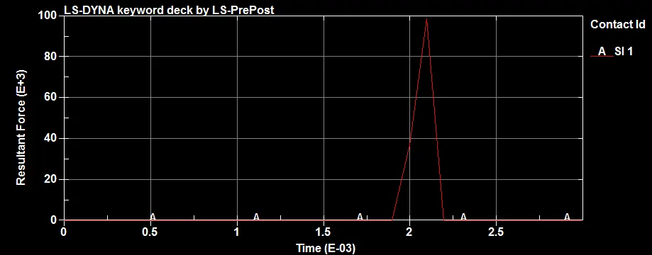
Fig: Resultant Force vs Time
From the above figure, we can able to see that the interface force increases only during the impact time and drops to zero in other regions. This interface force is the resultant force between the mobile phone and the bottom plate interface.
Element wise plots (Study-1)
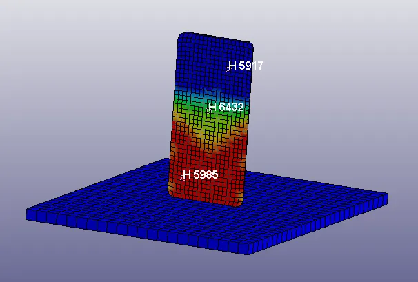
Fig: The above three elements took for study
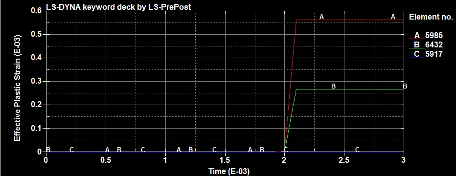
Fig: Effective Plastic Strain vs Time
Here element 'C' is far away from the impact region so that we can able to see there is no Effective plastic strain. But the other two elements especially element 'A' is increasing scalar value and such that the value remains constant once after the sudden impact finishes.
Element wise plots (Study-2)
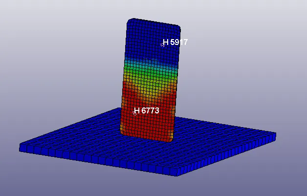
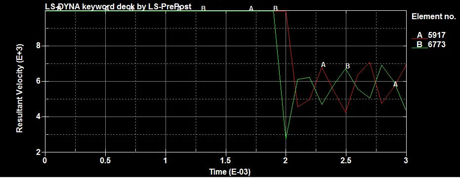
The velocity of the element 'B' drops when the phone hits the bottom plate, from 10m/s(10000mm/s) to 2.8m/s at 2ms and again increases to 6.2 m/s and at end of the simulation at 3ms it reached nearly 4.2m/s. Similarly, the element 'A' shows this velocity decrement once after the element 'B' because it is far away from the element 'B' and sees the lesser velocity decrement.
Conclusion:
- The complete simulation keyword file is generated from the primary file contained just nodes and elements of two parts.
- Added the keywords like material, initial velocity, section, boundary conditions, controls, database, and contact are properly assigned to create a basic solver deck to simulate a drop test.
- The study of mobile drop tests is been carried out and outputs for Vonmisses stress, Effective plastic strain is obtained by running the simulation, and energy, resultant force, strain graphs are also plotted.
The link for the mobile drop test model is attached below :
https://drive.google.com/drive/folders/1TX47ZvpEvO7PZ-BTipn1pU3pdCuI6N-s?usp=sharing