2-D Meshing of Rear Wheel Holder
Objective:
A Rear-wheel holder component is given for 2D mesh and to get the quality output as per given quality parameters and then assign them the thickness.
Theory:
Why do we extract mid-surface?
A mid surface is a surface between two surfaces. If we mesh the entire component in 3d the number of nodes and elements will increase which in turn would increase the storage space and processing power to analyze the component. To avoid this mid-surface is created where we represent the entire 3d model by mid-surface and create shell element.
Why do we perform meshing?
The basic idea of finite element analysis is to make calculations at only a limited number of points and then interpolate the results for the entire domain. Any continuous object has infinite degrees of freedom and it’s just not possible to solve this problem in this format. The finite Element Method reduces the degrees of freedom from infinite to finite with the help of discretization or meshing.
WHY we carry out meshing?
The answer is because the original component is having an infinite number of atoms in it and when we apply any force the displacement or strain has happened to every atom inside it, but an infinite number of displacements to find out is impossible. So we need to make the calculation finite. For that, we divide the component into a finite number of elements having a finite number of nodes. The most useful and popular 2d elements are quad and trias. Trias are being stiffer compared to quads they hesitate to transfer the force applied to them to nearby nodes so they are to be needed to minimize the meshing process. Each element having lines at the outer boundary which is based on the specific shape function of the element. We can find out the values of stress and strain at the nodes of the elements. Since we know the shape function of the element we can find out the displacement and stress values at the particular x and y as we need using the shape function.
For QUAD4 element shape function is `u = a_0 + a_1x+a_2y+a_3xy.`
FEA will calculate the values at nodes, ie `a_0,a_1, a_2, a_3`, Value of the variable in between nodes can easily find out using the above shape function. Each element will have several degrees of freedom. The degree of freedom is the number of variables with which the position of a node can be represented perfectly. Mostly the total number of degrees of freedom = total number of nodes x 6. since the 3 linear motion and 3 rotational motion along x,y, z-axis are possible for every node. Then the degree of freedom also depends on the type of Analysis we are to be carried out, the type of element we used in the meshing process. The higher number of order nodes in the mesh means higher accuracy. But the computational time will be high. Computational time is directly proportional to the power of the Degree of freedom, and n = 1 to 4 depending upon the solver we used for analysis.
Procedure:
The given component is a Rear-wheel holder which is a sheet metal component and these types of sheet metal components having varying thicknesses. They are also having a large number of fillets and other features inside the model. Since the third dimension which is thickness is very low, instead of going for 3D meshing, we can go for 2D meshing. For that, we need to extract the mid surface. Since the component is having a thickness that is varying, we cannot go for auto mid-surfacing since that will give only distorted mid-surface. So we should go for manual mid-surfacing.
1. File importing:
The first step in 2D meshing is to open the hyper work's software and in the interface it will ask to select a solver, here we select Optistruct as a solver. Then we need to import the IGES file which is the CAD file of the rear wheel holder
For that select File > Import > Then choose the rear wheel holder file from the directory > click on import.
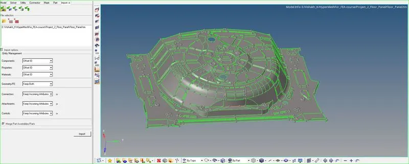
Fig: A view of Rear-wheel holder component
2. Geometry cleanup:
Here in the CAD model, the file imported may not be proper and some surfaces may get distorted in the process of importing. So we need to do the cleanup of the geometry. Some free surfaces may be presented in the imported model, some surface duplication may be seen, and some glitches in the surface, etc. will be presented. To remove all these issues before the process of meshing we need to do the topology clean up (F11). We can use the visualization option to see the free edges and surface duplications. For that uncheck the green lines which are of shared edges in the visualization option and then switch the model into the wireframe model. Then we can see the duplication of surfaces and free edges. If there are free edges in the geometry except at holes and outer boundary, then that is the indication of missing surfaces and improper connectivity. And if there is no T connection and still there are yellow lines present, then it is the indication that there is a duplication of surfaces or sharp surface which may get pasted.
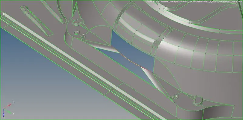
Fig: Deleted the sharp or needle surface from the geometry
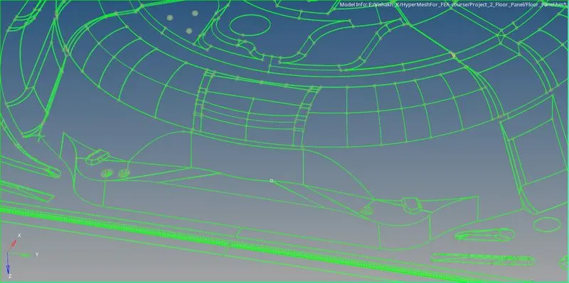
Fig: Created the surface using the Ruled option from surface
So we need to delete the duplicate surfaces and for removing the free edges which are red lines, we can use the Equivalence option in Tools> edge edit for checking them, the Toggle option in quick edit can be used to stick the edges together. If these two can’t solve the problem we can make use of spline and ruled surface options in the Surface panel. Also, we can use the replace point option in the quick edit tab.
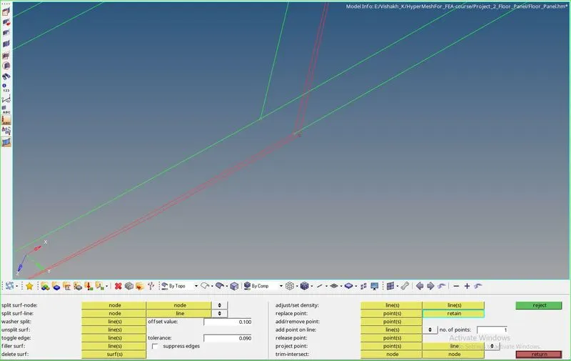
Fig: Replace point option used from quick edit panel
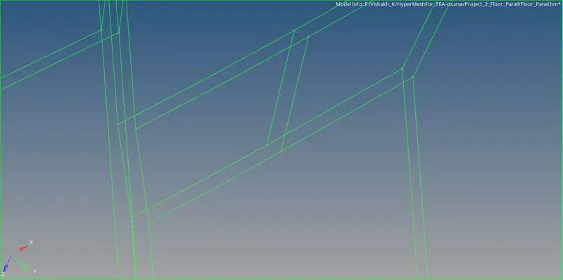
Fig: Connectivity in the Surfaces are done
After the geometry cleanup, we need to take the mid surface of the model. Since this is having a third dimension which is very less magnitude. We can take the mid-surface and mesh it in 2D and then we can add thickness to the mesh which is the same as the model. For viewing the thickness of the component, we can use 2D detailed element representation.
The geometry check or clean up, in that process we need to pay attention to our target element size, minimum element size, and maximum element size. We need to defeature the fillets which have the possibility of elements failing for minimum size. In these cases, we can refer to the Design engineers about the importance of those fillets. If those fillets are not that important then it is permitted to defeature those fillets. For defeature go to geometry tab > defeature > surface fillets > select the fillets we need to defeature > remove. If fillets are between 0.1 mm to 5 mm radius, then we can remove those fillets.
And if there are holes present in the surface and the holes id having a radius below 3 mm, then it is called a pinhole. We can remove or fill the pinholes for better meshing. To remove Pinholes go to geometry tab> Defeature> Pinholes > select the pinholes > Remove. Then the pinholes will be removed.
Provide washers to the holes above 5mm radius and if the radius is below 10 mm provide 6 to 8 elements inside the washer. And if the radius is above 10mm then it should mesh with 12 or more elements. The washer can be given by going to Quick Edit > provide offset > click on washer split >click on the edge of the hole, then we can see the washer split has appeared over the hole. Since there is the possibility of stress concentration near the holes, we need to mesh those areas with only quad elements. That’s why we provide washers in those regions. Other critical areas can find out by run the analysis and observe the results. The red-colored areas are high-stress areas and they are critical areas. We should mesh those areas with small element size for proper capturing of surface and with quad only elements.
Note: Cad engineers cannot provide the model in the same way as needed in meshing, because the design engineers design the components for purchase engineers and manufacturing engineers. So he kept in mind only the manufacturing perspective while designing. So CAE engineers should remodify the model as per our need.
3. Mid surface:
To take the mid surface of the fillets, measure the thickness of the fillet this can be done by using the Distance option by pressing F4. Then select the two points. Then choose the two points at the extreme on opposite sides to find the thickness. Then go to Geometry>Surface edit > OFFSET (or use the shortcut shift+F9) > select the outer surfaces of the body > choose a duplicate to current component > click on vector normal and see whether the offsetting in the right direction, if not then click on reverse normal > Then type in the offset distance as half of the thickness > Press offset. Similarly, every fillet and other features also mid-surfaced to the mid surface collector.
Here we can see that there will not be proper connectivity between the surfaces. So we can use the Drag the line option to drag the surface through the lower body part of the component. For that go to Geometry> Surface > Dragline > Select the line of fillet we need to drag through the surface > type in the distance to drag as some value so that the surface made by the line cuts the surface of the side door. Then we need to remove the additional protruding surface of fillet mid surface from the surface we can use the Trim with surfaces/Planes options for that go to Geometry panel > Surfaces Edit > select the trim with surfaces /planes > then select the surfaces we need to trim (Here it is the free edge surface of the fillet and the surface)> click on TRIM. This will be making a T-Connection with the surface of the side door and the free surface ie, the unwanted surface / extra surface can be deleted by using the delete option by pressing F2.
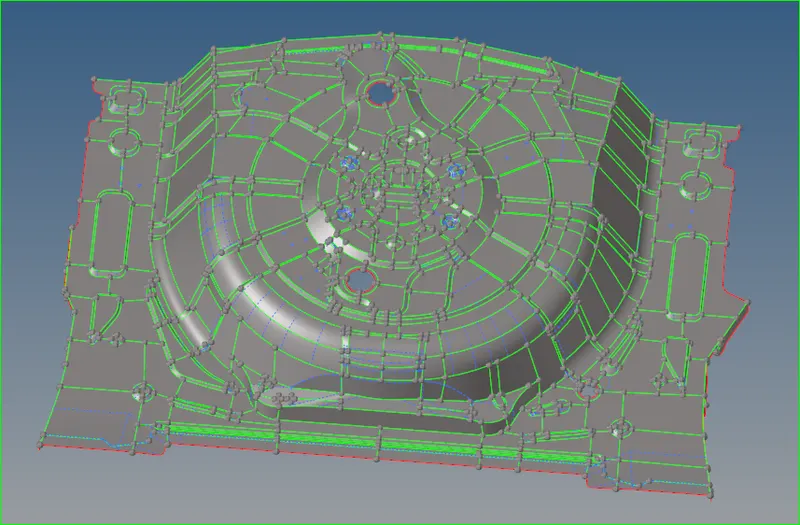
Fig: Final view of mid-surface extracted from the component.
4. Meshing:
Now we need to start meshing the mid surface, for that we can use the auto mesh option in the 2d panel.
Go to 2D Panel > Automesh > Select the surfaces needed to mesh > give the element size as 5 mm > Mesh
After the surfaces got meshed, by density option we can clean change the nodal densities at various locations to get a smooth mesh with a lower number of trias. Various things to keep in mind in meshing
If there are any opposite trias, we should re-mesh these trias, and thereby we can remove those trias. There should not be any mesh transition at the fillet regions.
A smoothing command can be used to smoothen the mesh. For that go to Tool panel > Click on smooth > Select the elements > Click on smooth
Never place TRIA elements at the edges or inside the washer.
Adjacent TRIAS must be removed. For that, we can use the Drag Tria option in the Quality Index tab in the 2D panel. We can select the tria and drag it to any other position so that we can remove the adjacent trias.
Rotating Quads are not acceptable in the crash analysis but acceptable in structural analysis. The same directional following tria elements are acceptable in the crash analysis but not permissible in structural analysis.
Always mesh the component keeping in mind the quality requirements and try to stick with the geometry capturing in the critical area.
5. Check for the connectivity of the mesh
Then we should check the connectivity of the elements in the mesh. For that, we should check whether there are any free edges present in between elements. For that Go to Tool panel > Find > choose to find edges, this will show the free edges in between the elements. To equivalence those free edges, Go to Tool panel > Find > choose to find edges > select the elements in between which the free edges are present > Preview Equivalence > Equivalence. This will ensure there are no free edges in between elements.
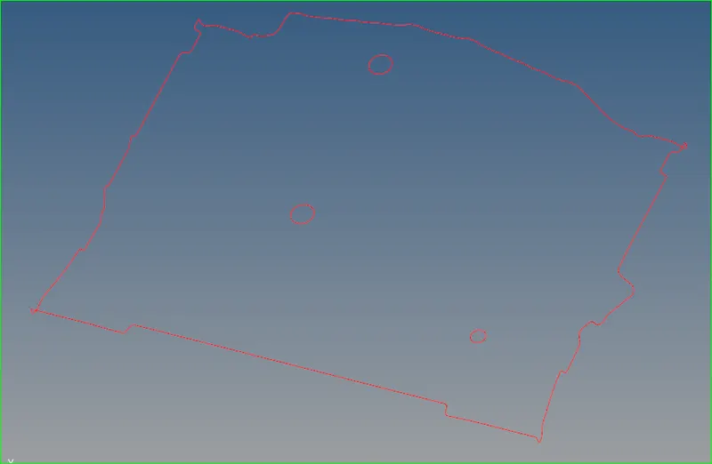
Fig: A view of free edged from the component
6. Checking for Quality criteria
Then we need to check for quality criteria. The quality requirements are given below. And the target element size is 5 mm.
| S.N | Quality Criteria | Value |
| 1 | Aspect Ratio | 5 |
| 2 | Skewness | 45 |
| 3 | Warping | 15 |
| 4 | Taper | 0.5 |
| 5 | Min. Length | 2mm |
| 6 | Max. Length | 8mm |
| 7 | Min angle Quad | 45 |
| 8 | Max angle Quad | 135 |
| 9 | Min angle Tria | 20 |
| 10 | Max angle Tria | 120 |
| 10 | Tria % | 10 |
Table showing Quality criteria data
After meshing some of the elements violates the quality criteria. This can be checked by Press F10 which is the check element tab. This can also be entered with Tool > check elements > type the quality relevant boxes. Then click on the respective options to check whether tab elements fail or not. So we should make them follow the quality criteria. For that the tools used are
- Replace node For that PRESS F3, the replace the nodes with each other
- Go to Quality Index then use Element optimize, this is used to optimize the elements based on the criteria we typed in the criteria file settings in the preferences option in the menu bar. Go to Preferences > criteria file setting > edit the quality criteria > then use element optimize and click on near the element we need to optimize. Yellow color elements mean the element is failed. But the red color element means the element is worst. Touching near the failed element with element optimization will optimize the element.
- Also, we can use the Place node option in clean up tools in a quality index. We can move the node along the surface /Normal to the surface to optimize the element.
- Also, a Smooth tool in the Tool panel can be used
- In case if elements need to split, then we can make of split element feature. For that press F6 and click on split and select the elements we need to split, then click the points through which we need to split the elements. Then click split. Then the elements will get split.
- Press F5 which is the mask option so we can save the elements from the check elements tab and then we can retrieve those elements using the mask option, and we can work on those failed elements without disturbing the other quality elements.
- Translate option can be used to solve the element failing issue for this first switch to element quality mode and find out the failed nodes. And press Shift+F4, so that the Translate option appears. Then choose the node and select the nodes in giving the direction of movement of the node. This option is used logically can solve many elements failing situations.
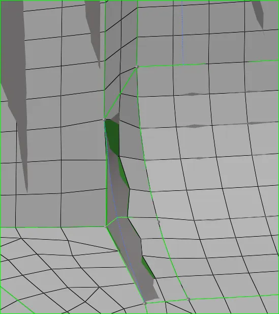
Fig: Due to geometry capturing we came up with these Quality criteria (ie, Warpage error)
7. Assign properties ie, thickness
Then next is assign the thickness for mesh just like the thickness of the actual model. For that create a property card with thicknesses and for that exact thickness of the component. The card creation is shown as below:
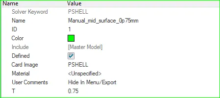
Fig: Property card defined for the shell elements
Go to 2D detailed representation will show as the mesh having thickness exactly same as that of the actual component.
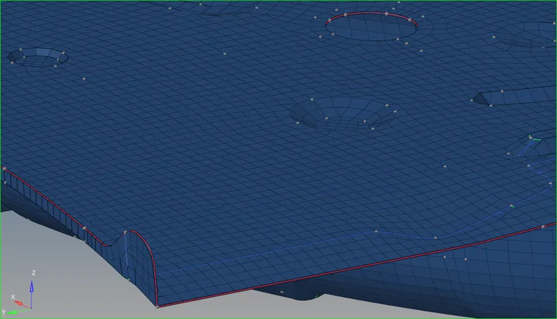
Fig: A view of the 2D representation of shell elements
Conclusion:
The process of meshing the complex sheet metal components is learned with this project, As a CAE engineer we should first study the geometry of the component and then carry out the meshing step by step and at last, we should apply the respective thicknesses to the part of the sheet metal component. We also need to give attention to geometry capturing and the mesh flows in the complex component as we saw here. Finally, in this project, the manual mid surfacing and meshing on the rear wheel holder component of a car were successfully performed. As checking the quality of mesh there were few warpages issued many of them fixed by several methods, but few of them as to be left alone due to geometry capturing in mind.