Modelling Spotwelds with Beam and Solid Element using LS DYNA and LS PrePost
Aim:
To model the spot-weld for the given assembly parts using beam and solid elements separately. Also, perform the crash analysis for the same and compare the output results of the beam and solid spot-welds.
Theory:
Spot welding (resistance spot welding) is a resistance welding process. This welding process is used primarily for welding two or more metal sheets together by applying pressure and heat from an electric current to the weld area. It works by contacting copper alloy electrodes to the sheet surfaces, whereby pressure and electric current are applied and heat is generated by the passage of current through resistive materials such as low carbon steels.
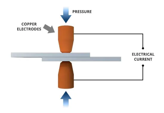
Fig 1: Schematic diagram of resistance spot welding
Procedure:
1. Open the spotweld-assignment.k file in LS-PrePost.
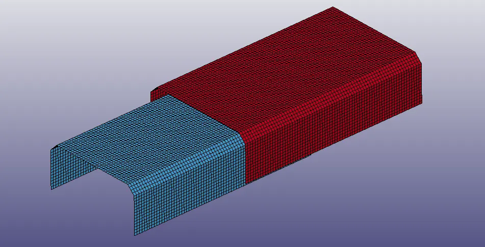
Fig 2: File opened in LS-PrePost
In the opened file, the bottom and top sheet metals have meshed with shell elements. The bottom and top sheet metals have meshed with 10011 elements/shells and 10296 nodes.
The unit system followed for the unit consistency is gm-mm-ms.
2. Create a Shell section card for the bottom and top sheet metals using the Model and Part > Keyword Manager > SECTION > Select the Shell option with Element formulation=16 and thickness = 1.2mm.
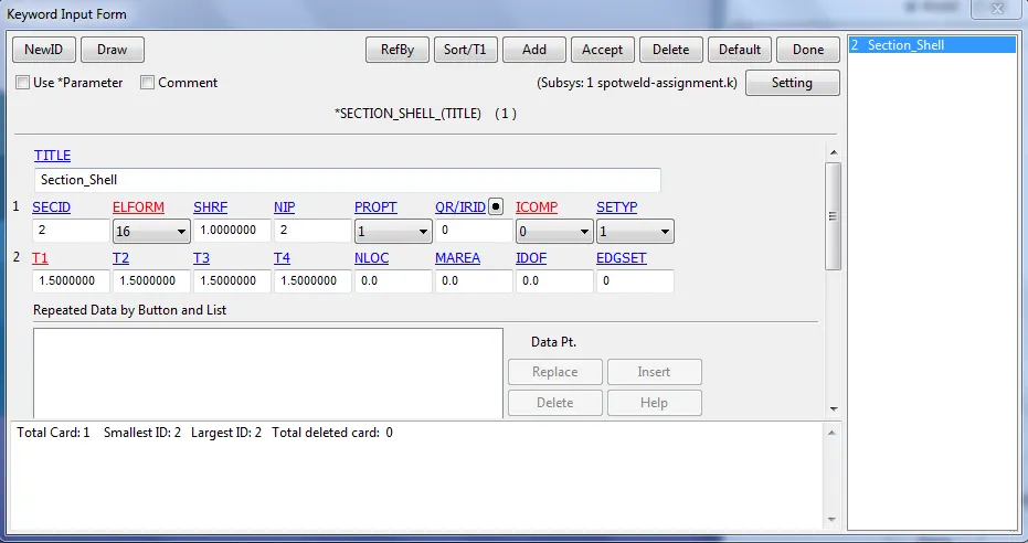
Fig 3: Defined Shell section card
3. Define the material for the bottom and top sheet metals. Select the 001-ELASTIC material card for the bottom and top sheet metals.
Model and Part > Keyword Manager > MAT > Select the Material card
Next, define the material properties like mass density, Young’s modulus, Poisson’s ration, Yield point stress value for the material cards.
- Density= 0.00785 `(gm)/(mm^3)`
- Young's modulus=2.10 e+05 `(gm)/(mm* ms^2)`
- Poissions ratio=0.3
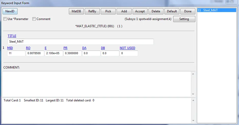
Fig 4: Defined the material card
4. Specifying the respective Material and Section ID to the bottom and top sheet metal part IDs.
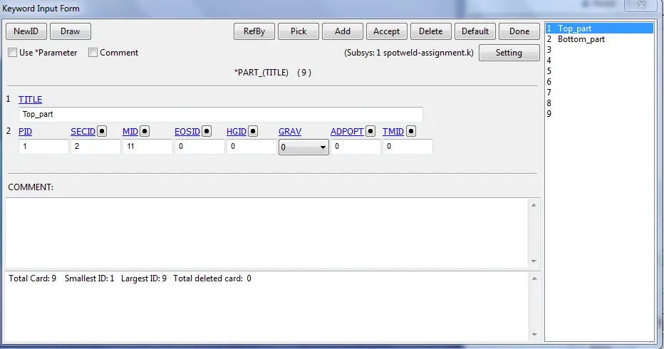
Fig 5: Specified the material and section card to the Part IDs
5. Next step is to create a Rigid wall in front of the top sheet metal part 15 mm away by using the *RIGIDWALL_PLANAR card
This is done by selecting Entity Creation > RigidWall > Create. The rigid wall type is selected as a Planar and defined vector with one point and a normal ie, 1n+NL here selected the one node, and the normal is created as a rigid wall. This rigid wall is translated/offset by 15mm from the crash box component.
The blue outer line shows the exact location of the rigid wall from the crash box component.
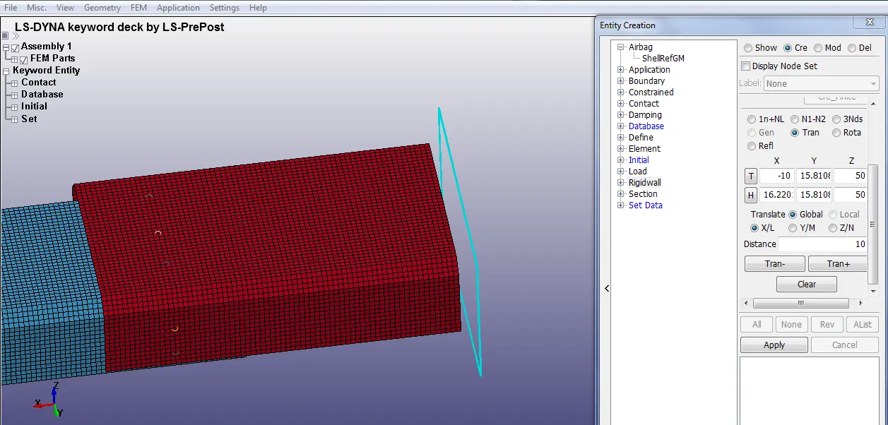
Fig 6: Created a Rigid wall in front of the bottom sheet metal part
6. Next step is to define a velocity of 50kmph (13.8889 mm/ms) and assigned to each node of the selected bottom and top sheet metals, under Entity Creation >Initial>Velocity>Insert the value. The bottom and top sheet metals are selected by pick option with respect to part as shown below.
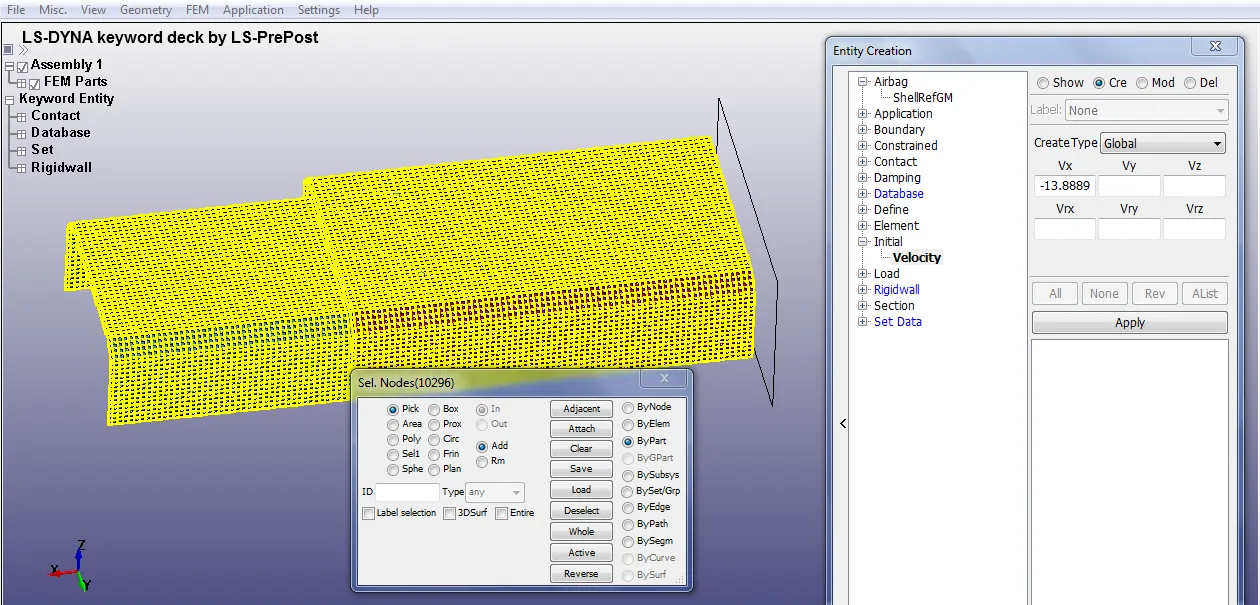
Fig 7: Defined a velocity to the bottom and top sheet metals
Note: The direction of normal (here x-direction) from the rigid wall and the velocity vector (x-direction) should be in the opposite direction in order to avoid the penetration of the crash box through the rigid wall which is not acceptable since it is a rigid wall and the component is a material which shows the plasticity.
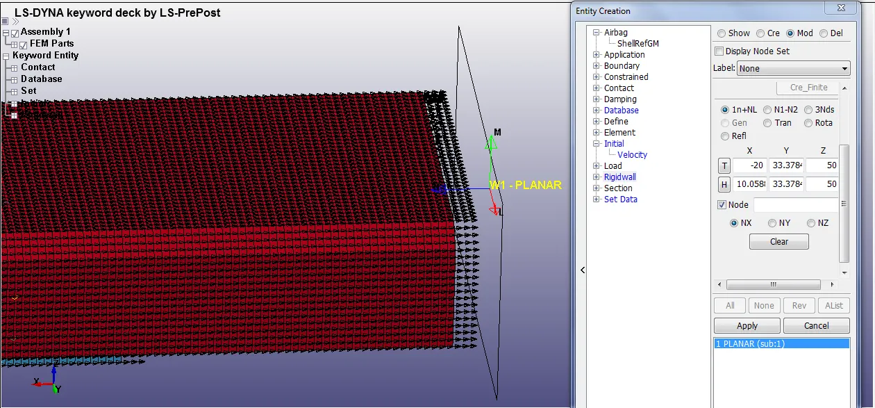
Fig 8: Normal from the Rigid wall and Velocity component in X-direction checked.
7. The spot-weld can be modeled as beam and solid elements by using the following techniques,
- To represent as a beam element, we use *CONTACT_TIED_SHELL_EDGE_TO_SURFACE card
- To represent as a solid element, we use *CONTACT_SPOTWELD card
Spot-weld modeled using Beam element:
The spot weld modeled using beam element is created by selecting the Mesh > Element Generation > Beam > Give Part ID > Select Beam by Two_Node_Sets > Pick Node set 1 & 2 (pick the desired nodes from bottom and top sheet metal) > Create > Accept > Done
Now this beam element act as a spot weld.
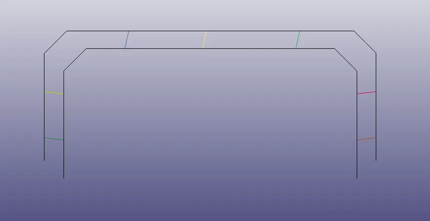
Fig 9: Spot-weld modeled using beam elements
Note: Here the fact is that automatically a Section card (*SECTION_BEAM) and the Material card (*MAT_CABLE_DISCRETE_BEAM) are created and we need to delete these cards and assign our required material and section cards.
Defining the Material card for Beam Element
For the beam element, the material card is assigned as the *MAT_100 that is especially for the spot weld material. The values are assigned and here we are taking a time-dependent failure concept rather than the force-dependent failure concepts like Effective plastic strain, maximum axial stress, maximum shear stress, Force resultant, Torsional moment resultant, Moment resultant. So to keep this problem as a Time-dependent failure we given other failure terms as a higher value.
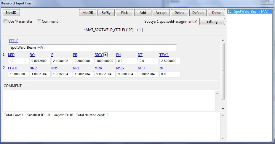
Fig 10: Defining the Material card for Beam Element
Defining the Section card for Beam Element
For the beam element, the section property is assigned by using the *SECTION_BEAM card. It is important to assign element formulation (ELFORM) as 9 because the *MAT_100 spot weld material model only applies for ELFORM 9 formulation in the case of the beam element. The cross-section type is selected as tubular since the default cross-section(rectangular) gives zero cross-section area during the simulation and the beam thickness at both ends is given as 3mm.
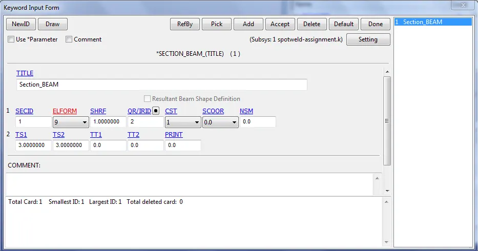
Fig 11: Defining the Section card for Beam Element
Defining the Contact card for Beam Element
Here for the beam element, the contact type to be used is *CONTACT_TIED_SHELL_EDGE_TO_SURFACE card.
Here the master set id will be Part id and the Slave set id will be nodes of beam weld element.
For defining the Slave set select beam nodes so as to create the set and the steps is mentioned below,
Entity Create > SetData > *SET_NODE > Pick the nodes > Apply.
For defining the Master set select both the metal sheet parts and the steps is mentioned below,
Entity Create > SetData > *SET_PART > Pick the part > Apply.
So assign both the slave-set and the master-set as created by the above technique to the contact card. *CONTACT_TIED_SHELL_EDGE_TO_SURFACE card.
Slave-type - Node set ID
Master-type - Part set ID
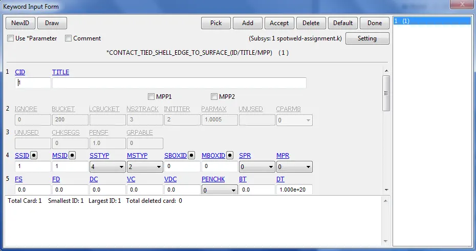
Fig 12: Defining the Contact card for Beam Element
Note: Also we need to create an Automatic_single_surface contact card for the parts to ensure that after the spot weld breaks the parts come to each other they shouldn't penetrate. Here the parts-sets are the slaves
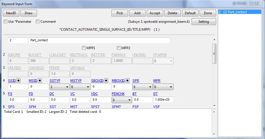
Fig 13: Defining the Contact card for sheet metal parts
Spot-weld modeled using Solid element:
The spot weld modeled using solid element is created by selecting the Element Tools > Element Editing > Create > Type - Hexa > Pick four desired nodes from the bottom and top sheet metal > Accept > Done
Now this solid element act as a spot weld.
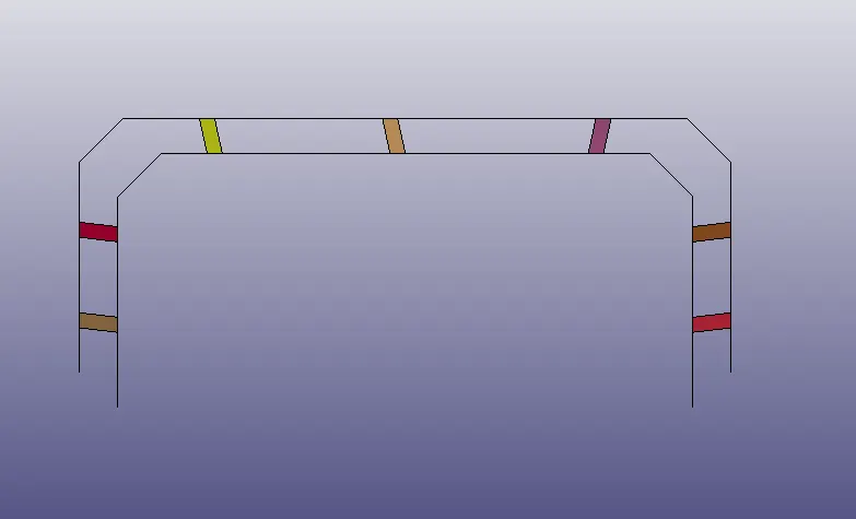
Fig 14: Spot-weld modeled using Solid element
Defining the Section card for Solid Element
For the solid element, the section property is assigned by using the *SECTION_SOLID card. It is important to assign element formulation (ELFORM) as 1 because the *MAT_100 spot weld material model only applies for ELFORM 1 formulation in the case of the solid element.
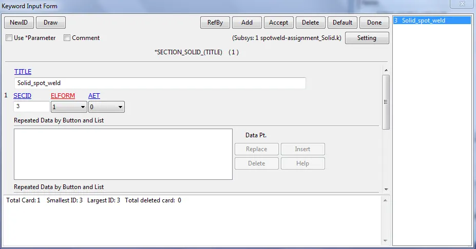
Fig 15: Defining the Section card for Solid Element
Defining the Contact card for Solid Element
Here for the solid element, the contact type to be used is *CONTACT_SPOTWELD card.
Here the master set id will be Part id and the Slave set id will be nodes of solid weld element.
For defining the Slave set select solid nodes so as to create the set and the steps are mentioned below,
Entity Create > SetData > *SET_NODE > Pick the nodes > Apply.
For defining the Master set select both the metal sheet parts and the steps is mentioned below,
Entity Create > SetData > *SET_PART > Pick the part > Apply.
So assign both the slave-set and the master-set as created by the above technique to the contact card. *CONTACT_SPOTWELD card.
Slave-type - Node set ID
Master-type - Part set ID
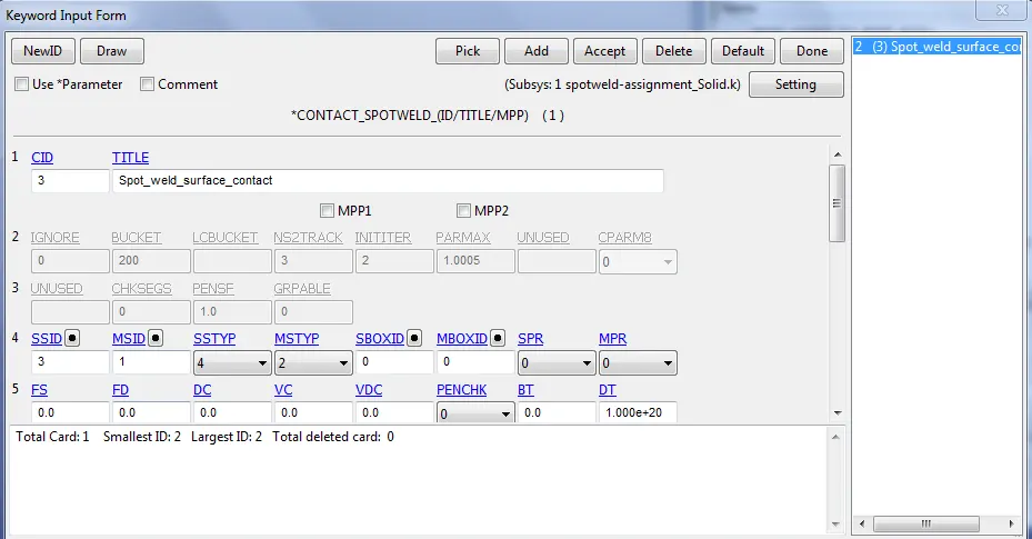
Fig 16: Defining the Contact card for Solid Element
Defining the Material card for Solid Element
For the solid element, the material card is assigned as the *MAT_100 that is especially for the spot weld material. The values are assigned and here we are taking a time-dependent failure concept rather than the force-dependent failure concepts like Effective plastic strain, maximum axial stress, maximum shear stress, Force resultant, Torsional moment resultant, Moment resultant. So to keep this problem as a Time-dependent failure we given other failure terms as a higher value.
8. Next the Termination time is to be assigned by using *CONTROL_TERMINATION card. Here the time to end the simulation can be calculated analytically by using the distance between the rigid wall and component ie,15mm, and the velocity of the crash box ie,13.8889 mm/ms.
End time, t = (15mm)/(13.8889 mm/ms) = 1.0799ms
The calculated time is 1.4399ms but extra time is considered after the impact in simulation ie, the crashing and the bouncing back of the crash box. So, the total time of 5ms is assigned as end time in the *CONTROL_TERMINATION card.
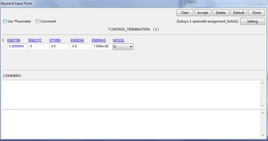
Fig 17: Defining the Control Termination card for both the simulation
Note: Calculate the energy dissipation, Hourglass energy, rigid wall energy, sliding interface energy that can be done by *CONTROL_ENERGY card, and to control Hourglass formulation in the beam element. Since in the solid spot weld we used the full integration so there is no effect of the hourglass.
9. Now, the following output data is generated by using the *DATABASE card with a time step of 0.5ms are assigned for generating output data.
DATABASE_BINARY_D3PLOT --> Used to find out the animation of the process,
DATABASE_ASCII_NODOUT --> To find the Nodal motions,
DATABASE_ASCII_ELOUT --> To find the element data,
DATABASE_ASCII_GLSTAT --> To find the global statistics and energies,
DATABASE_ASCII_MATSUM --> To find the material energies,
DATABASE_ASCII_SECFORC --> To find the Cross-section forces data
DATABASE_ASCII_SWFORC --> To find Spotweld Nodal Constraint Reaction Forces
For generating section forces creating a specific node and element/shell list which defines the desired section of component is necessary. The selection of nodes and elements/shell lists is done by picking each node and element through Creating Entity>Set Data>*SET_NODE for node-set and Creating Entity>Set Data>*SET_SHELL for element/shell-set.
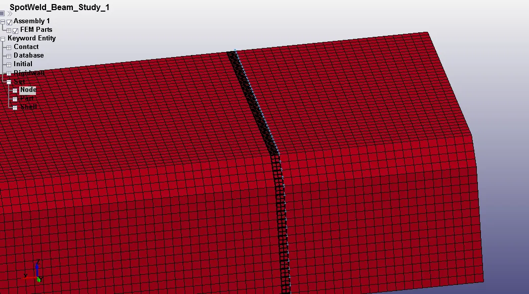
Fig 18: Node and shell set created
10. After assigning all the above-mentioned keywords, the model is ready for the simulation. Save both the keyword files and open in the LS-DYNA manager which solves the problem.

Fig 19: Saved keyword file ran in LS-DYNA solver
Von Mises Stress contour plot after the spot weld fails:
The von Mises yield criterion states that if the von Mises stress of a material under load is equal or greater than the yield limit of the same material under simple tension then the material will yield.
In both the simulation the component hits the rigid wall at 1.0799ms of the simulation, the spotweld fails, exactly half the termination time ie, 2.5ms. There is no abnormal behavior of elements during the simulation since the element's materials are defined using the elastic property. After the spot weld fails we can see that the top and bottom parts come into contact and causing the stress at the contact area and which is shown in the above contour as a red-colored region.
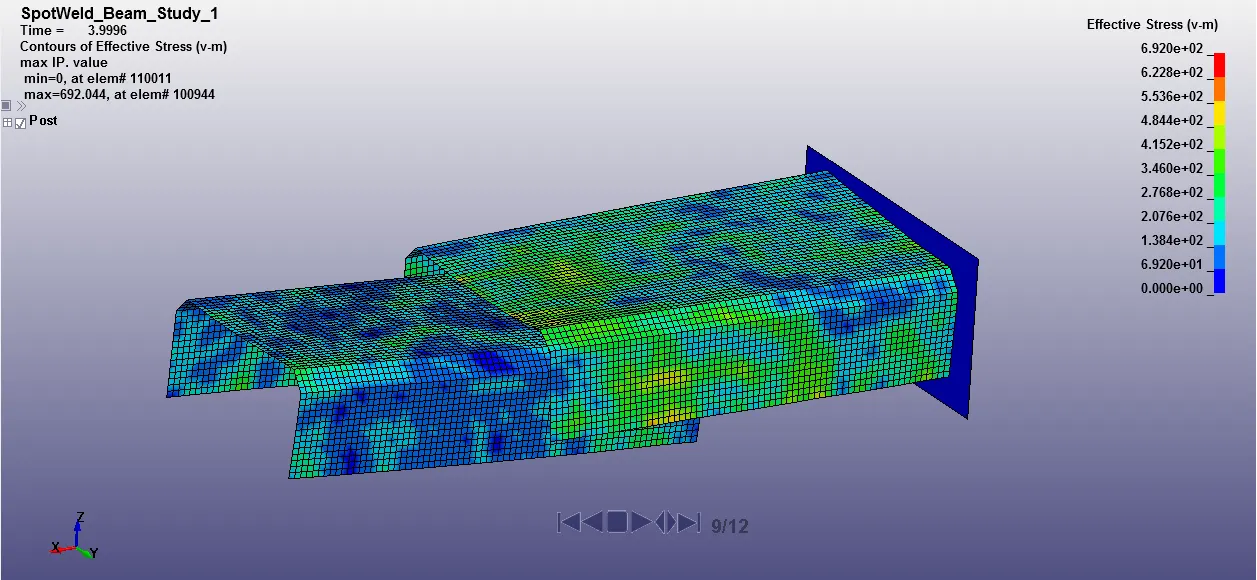
Fig 20(a): Effective Stress(v-m) for study-1 (Beam spot weld)
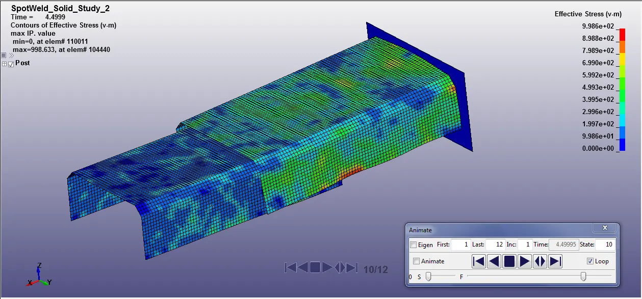
Fig 20(b): Effective Stress(v-m) for study-2 (Solid spot weld)
Output Results:
GLSTAT - Global Energies plot
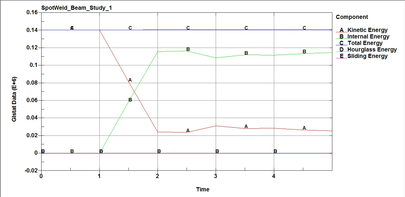
Fig 21(a): Energy plot for study-1 (Beam spot weld)
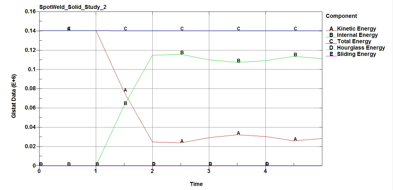
Fig 21(b): Energy plot for study-2 (Solid spot weld)
From the plots above ie, the study of the beam and solid weld, here initially the sheet metal parts had a velocity of 13.8889mm/ms and as they impacted the rigid wall we can able to see that the Kinetic Energy of the component is been decreased and between in terms internal energy of the component is been increased higher and the hourglass energy is fall to zero as we controlled it in both the case study. The total energy of the system remains constant.
NODOUT - To find the Nodal motions
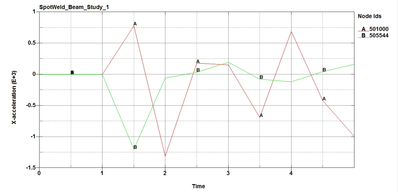
Fig 22(a): Nodal acceleration plot for study-1 (Beam spot weld)
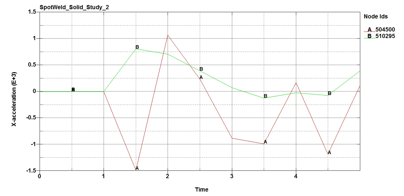
Fig 22(b): Nodal acceleration plot for study-2 (Solid spot weld)
Here the nodes are selected from the top and the bottom part of the sheet metal A-node represents the top part node and B-node represents the bottom part node. It can be seen that after the impact the acceleration is not constant, at first the acceleration values decreases due to a drop in velocity of the component ie, acceleration (-ve velocity), and then goes up and down as shown in the figure above. The top metal sheet bounces back due to the impact whereas the lower metal sheet part connected with the spot weld continues to travel in the same direction due to momentum from the top part.
SWFORC - To find Spotweld Beam & Solid Axial and Normal Forces
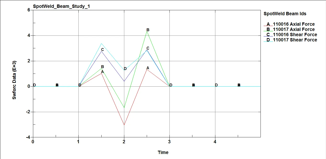
Fig 23(a): Axial and Shear force plot - Beam spot weld
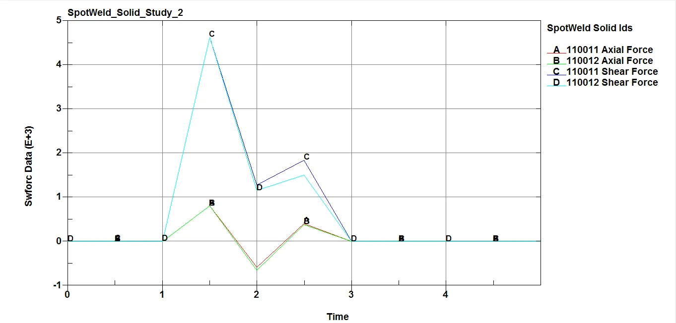
Fig 23(b): Axial and Shear force plot - Solid spot weld
Here the study carried out by modeling the spot weld at the 7 locations ie, 2 numbers each at the left and right sides as shown in the above figures and 3 numbers at the top side so that the top and bottom metal sheet parts are held together.
The problem with the beam element is that it takes load only in the one direction as focussed and shear load is not easily understandable from the results. So in the above figure too, we can see that the higher axial forces can be seen compared to shear forces for spot welds modeled by the 1D beam element. The force values drop to zero after the spot weld fails (ie, after 2.5ms). Whereas, higher shear forces are notices comparatively to axial forces for spot welds modeled by solid element. The force acting on the spot weld is in the transverse direction (perpendicular to the axis) since the solid element gives the force-resisting ability in the transverse direction, higher shear force values are notices for a solid element than beam element.
Link for both the simulation file:
https://drive.google.com/drive/folders/18moXHniEXkEiT3up71Xi1DD2acq_5bZh?usp=sharing
Conclusion:
- The spot welds are modeled using Beam and Solid elements for the same component.
- The material card and all other keywords are properly defined for the simulation.
- The simulation carried out with time-dependent failure and spot weld is failed at half of the termination time.
- The component bounces back after impacting on the rigid wall.
- The plot results and contour diagrams are compared.