Meshing and Connections for a Car Suspension System using ANSA
Aim:
To check the geometrical errors on the given suspension system and mesh the component with given quality criteria using tetra elements where the thickness is not uniform and with mixed elements (Tria and Quad) where the thickness is uniform (thickness less than 5mm). Also, deploy connections in the required area of the component.
Theory:
Suspension system:
The purpose of the suspension system is to isolate the vehicle body from road bumps and vibrations while keeping the wheels in contact with the road.
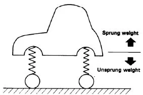
Figure a: Shows the Sprung and Unsprung weight
Sprung weight is a term used to describe the parts of a car that are supported by the front and rear suspension springs. These are Vehicle's frame, body, engine, driver, all liquids, and the power train above the wheels. These are quite heavy assemblies.
The Unsprung weight includes wheels, tires, brake assemblies, rear axle assembly, and other structural members which are not supported by the suspension springs.
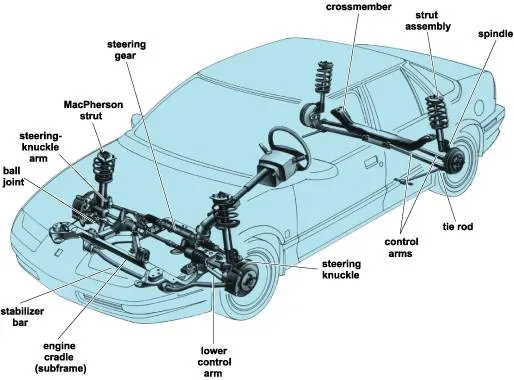
Figure b: Layout of the Suspension system
Principle of Suspension: The suspension system isolates the vehicle body from the road shocks and vibrations which otherwise would be transferred to the passengers and also to the load. It must also keep the tires in contact with the road.
For example: when a tire hits an obstruction, there is a reaction force. The size of the reaction forces depends on the unsprung mass of each vehicle assembly. The sprung mass includes the body, frame, and engine which are supported by the springs. While the unsprung mass includes the tires, wheels, brake assemblies, etc. The vehicle ride handling and quality can be improved by keeping the unsprung mass as low as possible, but the suspension systems should be strong enough to withstand the loads imposed on it during cornering, braking, and uneven road surfaces.
Suspension Force: Applying a force to an object deforms it. Automotive suspensions generally use the elastic properties of the metals so as to provide the springing medium. The springs are located between the frame and axle assemblies. Leaf springs are semi-elliptical and they absorb the force by flattening under load while coil springs absorb the force by twisting. Torsion bars are held rigid at one end and twist around their center as the suspension arm is deflated. Nonmetal materials like rubber can provide the main springing action but are commonly used as stops to limit suspension movement. In light vehicle applications, the air is normally used for ride height control.
For example: When the vehicle hits an uneven surface, the spring deforms from their original shape and returns to their normal position but tends to overshoot and set up oscillations. This makes the vehicle bounce up and down making the ride uncomfortable due to which the tires won’t be able to grip the road surface well. The shock absorbers have a marked effect on how well the tires follow a road surface. They damp the natural bounce over the road and reduce spring oscillations. There are different kinds of shock absorbers but they use a piston sliding inside a cylinder filled with oil.
Suspensions parts: The suspension of a car is actually part of the chassis, which comprises all of the important systems located beneath the car's body. These systems include:
- The frame - structural, load-carrying component that supports the car's engine and body, which are in turn supported by the suspension
- The suspension system - a setup that supports weight, absorbs and dampens shock and helps maintain tire contact
- The steering system - the mechanism that enables the driver to guide and direct the vehicle
- The tires and wheels - components that make vehicle motion possible by way of grip and/or friction with the road
Classification of Suspension System: Suspension systems are important in the vehicle structure. A suspension system consists of springs, shock absorber, axles, rods, and ball joints. Basic types of springs are leaf springs, Coil springs, and Torsion bars. They are basically divided into two types of systems one is the independent system and the other is the dependent suspension systems.
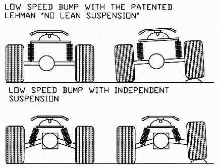
Figure c: Dependent and Independent suspension system
Dependent / Conventional suspension systems: In this type of suspension system, both wheels of the same axle are rigidly connected to the same suspension system. The force acting on one wheel affected the motion of another wheel. The main advantage of this type of suspension system to the weight carrying capacity of it is more than other types of suspension systems. So this type of suspension is mostly used in heavy-duty vehicles like trucks, buses, and commercial vehicles.
- Solid Rear Axle Suspension
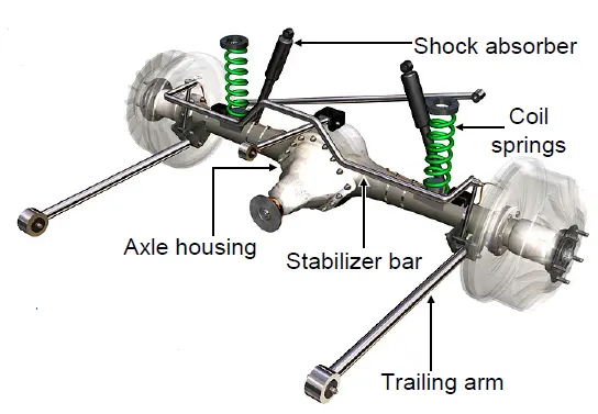
Figure d: Conventional Rear Suspension
This type of rear suspension is typical for a rear-wheel-drive vehicle and the axle is inside a solid housing. The shock absorbers are mounted between the solid axle and the frame. The springs are arranged between the axle housing and the frame of the vehicle.
Trailing arms, or links, hold the rear axle in position, and a stabilizer bar and track bar are included to add vehicle stability.
Independent suspension systems: In this type of suspension system both wheels of the same axle connected with different suspension systems so the force acting on one wheel will not affect the motion of the other wheel. This type of suspension system provides more comfort compared to the dependent suspension system. This provides better handling and riding comfort so it is used in the cars and Volvo bus etc.
This type of suspension usually offers better ride quality and handling due to less unsprung weight. The main advantage of independent suspension is that they require less space, they provide easier steerability, low weight, etc.. Examples of Independent suspension are
- Double Wishbone
- MacPherson strut
Double Wishbone:
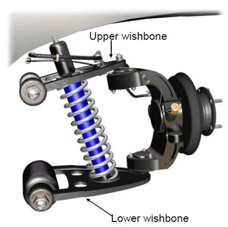
Figure e: Double Wishbone
It is an independent suspension system design using two wishbone-shaped arms to locate the wheel. Each wishbone or arm has two mounting points to the chassis and one joint at the knuckle. The angle movements of the compressing and rebounding wheels can be managed by using arms of unequal length
The main advantage of the double-wishbone suspensions is that they allow easy adjustments of camber, toe, and other properties. On the other hand, it takes more space and is slightly more complex than the other system like Macpherson strut. It also offers fewer design choices.
MacPherson strut:
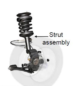
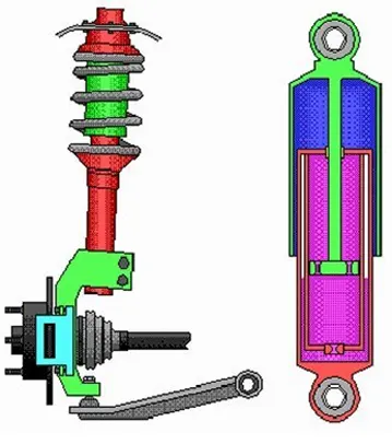
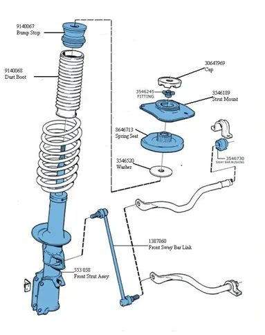
Figure f: MacPherson strut
Consists of a shock absorber, a coil spring, and an upper damper unit. Strut assembly often replaces the upper control arm and connected to the steering knuckle.
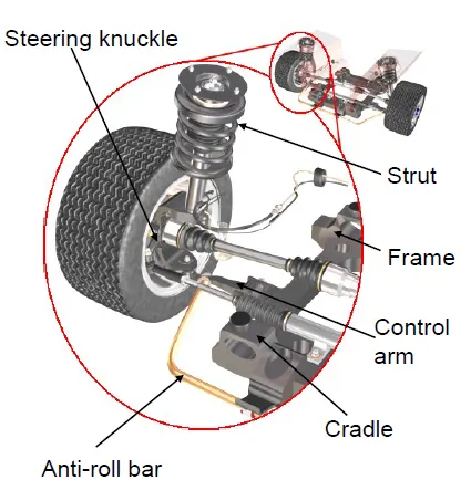
Figure g: Parts of MacPherson strut
This type of independent suspension got its name from Earle S. McPherson who developed this design. The MacPherson strut is a further development of the double-wishbone suspension. The main advantage of the MacPherson is that all the parts providing the suspension and the wheel control can be combined into the one assembly.
It makes it easy to fit in a transverse engine. This design is very popular due to its simplicity and low manufacturing cost. The disadvantage is that it is more difficult to insulate against road noise. for this, an upper strut mount is necessary, which should be decoupled as possible. It also requires greater clearance height.
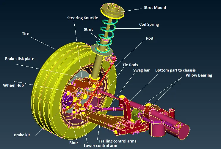
Figure h: Denoted different parts in the suspension system taken for the below study
Control arm – a movable lever that fastens the steering knuckle to the vehicle’s body or frame.
Steering Knuckle – provides a spindle or bearing support for the wheel hub, bearings, and wheel assembly.
Ball Joints – swivel joints that allow control arm and steering knuckle to move up and down and side to side
Springs – supports the weight of the vehicle; permits the control arm and wheel to move up and down.
Shock absorbers/dampeners – keeps the suspension from continuing to bounce after spring compression and extension.
Control arm bushing – sleeves that allows the control arm to swing up and down on the frame.
Swag bar - Used to keep the body from leaning excessively in sharp turns and fastened to lower control arms
Objective:
- Geometry cleanup.
- Assign PIDs for the different parts in the suspension system.
- Midsurface extraction for uniform thickness which is having less than 5mm thick and for the rest we can deploy a Solid mesh/ 3D mesh.
- Assigning suitable thickness and materials for PID
- From the extracted mid surface we need to deploy Shell meshing with mixed elements.
- Volume/ Solid meshing can be deployed once after doing a shell mesh on the surface so that proper mesh growth can be seen and as well as tetra collapse can be eliminated.
- Meshing to be done under the quality criteria.
- Connections like Bolt, Weld, Rigid to be implemented.
- Symmetrical Transform to be deployed
Procedure:
1. File opening in Ansa environment
Firstly open the given rear suspension system (.ansa file) in Ansa
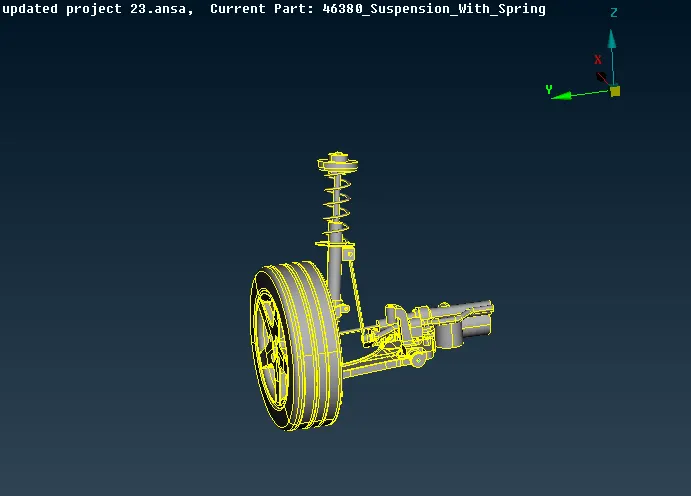
Figure 1: Model opened in Ansa
2. Geometry cleanup - Initial steps
A topo operation is performed on the model to view the single cons, double cons, and triple cons.
Topo module > Faces > Topo
The model is oriented in such a way that the outside face is in grey color and the inside face is in yellow color and this will give a good orientation at the time of mid surface extraction.
Topo module > Faces > Orient
3. Geometry cleanup - Geometry check
The suspension model is checked for all geometrical errors like Single cons, Unchecked faces, Collapsed cons, Triple cons, Neddle faces, Overlap faces, and Cracks.
Checks manager > Geometry > Execute
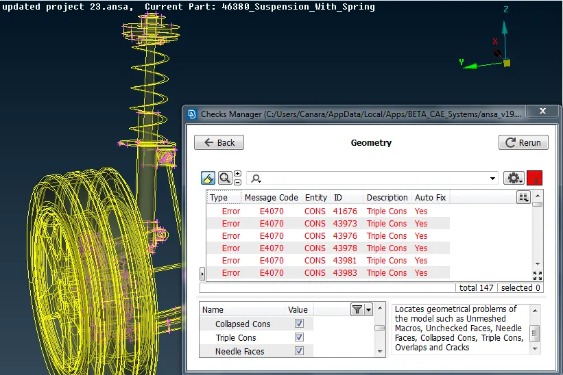
Figure 2: Geometry check-up
Here the geometrical errors should be fixed manually. In the Tire part, we can see duplicate face formation as shown below. So the duplicate face has to be deleted so that we can overcome the triple cons errors.
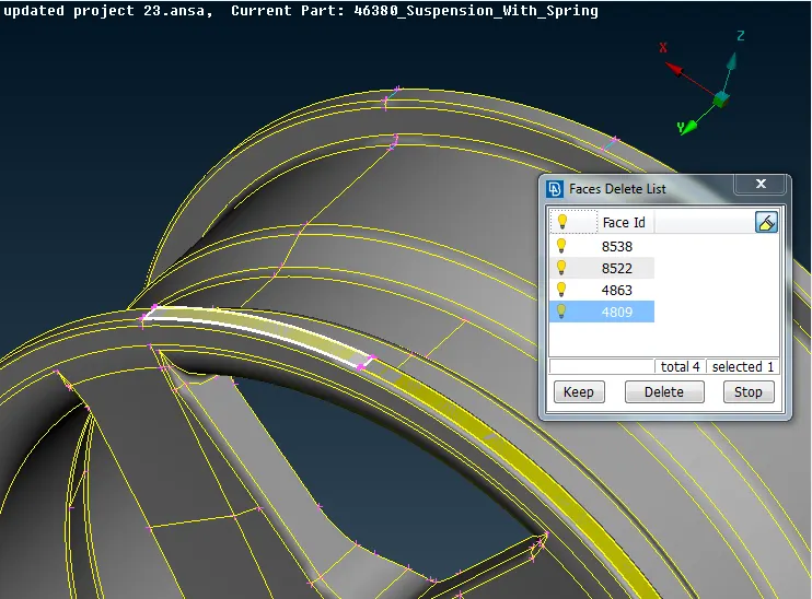
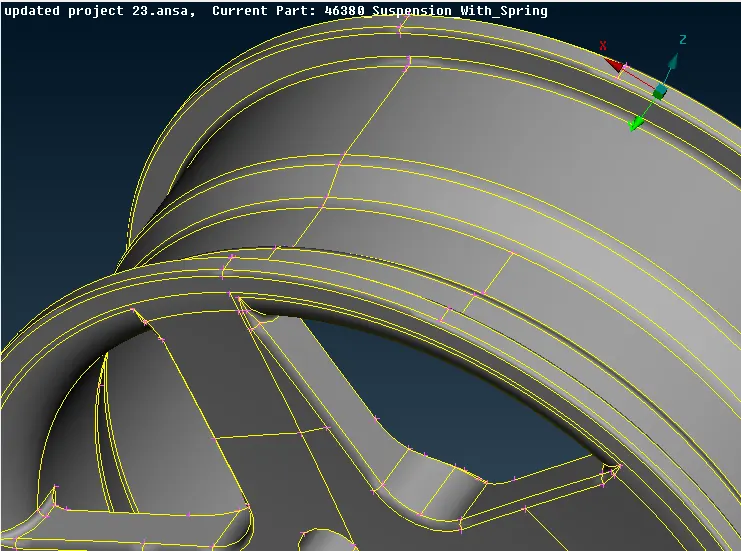
Figure 3&4: Working on geometric errors manually (Duplicate faces).
The model is once again checked for all geometrical errors and the geometry is finally cleaned up.
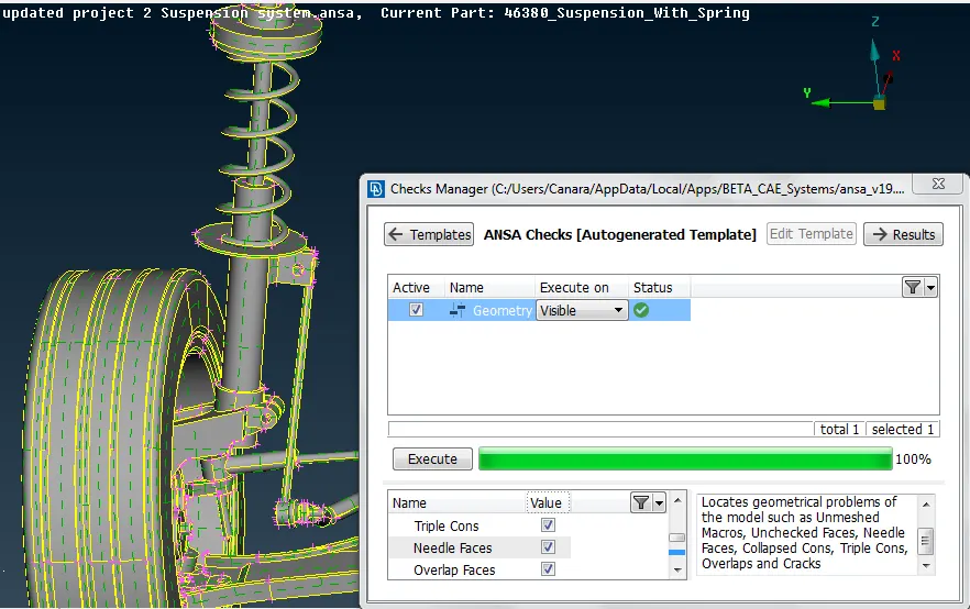
Figure 5: Conforming Geometry clean up
4. Setting the parts in different PIDs
Given the suspension system is broken into different components and set PIDs, check the thickness of each component. If the thickness is less than 5mm extract the mid surface and if it is more than 5mm component chooses for the solid mesh according to the given quality criteria.
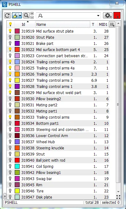
Figure 6: Setting PIDs
Theory on 2-D and 3-D Quality Criteria
Quality Criteria in 2-D Meshing
There are two types of two-dimensional cell shapes that are commonly used. These are the triangle(tria) and quadrilateral (quad).
Aspect Ratio:
The aspect ratio is the ratio of maximum edge length to the minimum edge length of an element. The ideal value of the aspect ratio is 1. That means all the sides of an element are of equal length. If the aspect ratio is greater than 5, it means that the max length is 5 times greater than min. length of the element and the element is said to be failed in aspect ratio criteria. However, an aspect ratio of less than 5 is generally accepted.
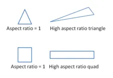
Fig i: Aspect ratio of a tria and quad element
Skewness:
Skew in trias is calculated by finding the minimum angle between the vector from each node to the opposing mid-side and the vector between the two adjacent mid-sides at each node of the element. Ninety degrees minus the minimum angle found is reported.
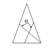
Fig j: Tria element; tria skew = 90- `alpha`
Skew in quads is calculated by finding the minimum angle between two lines joining opposite mid-sides of the element. Ninety degrees minus the minimum angle found is reported.
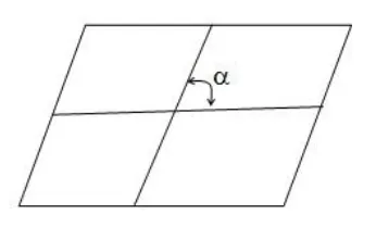
Fig k: Quad element; quad skew = 90- `alpha`
Warping:
It is defined as the angle between the normals to two planes formed by splitting the quad element along the diagonals. The maximum angle of the two possible angles is reported as the warp angle.
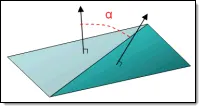
Fig l: Warp angle mentioned
Jacobian:
The Jacobian is a scale factor arising because of the transformation of the coordinate system. Elements are transformed from the global coordinates to local coordinates (defined at the centroid of every element).
Minimum and Maximum length:
Here the average element length is taken as 5mm and minimum length has 3mm and maximum length as 7mm
Minimum and Maximum angle of quad and trias:
Similarly to the length of the element angle between the edge of the quad and tria is also taken under the quality criteria
Triangles %:
Since it is mixed elements considered for the meshing so we taking a percentage of trias to be present in the meshing.
Quality Criteria in 3-D Meshing
The ideal shape for a tetrahedron element is an equilateral tetrahedron (all equilateral triangle faces). Various quality parameters check how far a given element deviates from the ideal shape.
Tetra Collapse
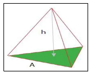
Fig m: Warp angle mentioned
Ideal Value = 1.0 (Acceptable > 0.1)
Tetra collapse = (min of h /√ A) / 1.24
The height of the tetra element is measured from each of the four nodes to its opposite face, and then divided by the square root of the face’s area, the minimum of the four resulting values (one per node) is then normalized by dividing it by 1.24.
5. Volume meshing steps:
The Spot Mesh algorithm gives better results than the free and best meshing algorithm and creates the optimum number of elements and the algorithm gives a good mesh with respect to the type of cad - geometry opened. So used the Spot mesh algorithm for the Ortho tria shell meshing and Best mesh algorithm for the mixed shell meshing.
The following Quality criteria are to be taken into consideration while meshing Tire and Rim. These parameters are to be entered in quality and mesh parameter tabs.
Quality Criteria for Tria Elements (Tyre and Rim):
|
S.No |
Quality Criteria |
Value |
|
1 |
Target/Average length |
6.5 |
|
2 |
Minimum Length |
5 |
|
3 |
Maximum Length |
10 |
|
4 |
Skewness |
45 |
Quality criteria for Tria (For other components):
|
S.No |
Quality Criteria |
Value |
|
1 |
Target/Average length |
4 |
|
2 |
Minimum Length |
2 |
|
3 |
Maximum Length |
6 |
|
4 |
Skewness |
45 |
6. Initially done the shell meshing
The next step is to mesh the geometry with the tria elements and we can choose either ortho tria or tria. If in case we need to mesh the feature like fillet and curved faces we will go with the ortho tria since it captures the features pretty well and in a proper way and in the flat faces we can go with the tria since the tria and ortho tria gives similar results in the flat faces.
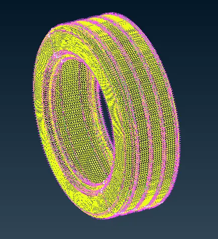 Figure 7: Tire shell meshed
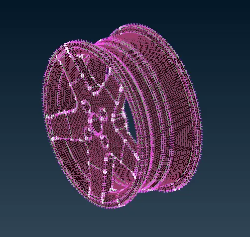 Figure 8: Rim shell meshed
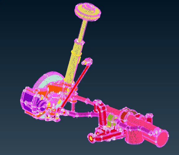
Figure 9: Rest of the parts in the suspension system.
Volume meshing:
Now, this shell mesh is to be defined as a solid mesh by the following steps:
Volume mesh module > Volumes > Define > Manual
For defining a volume we need already meshed macros or FE-model mesh.
After defining the shell mesh in the Volume module we need to select the List options from the Volume options in the same Volume mesh module.
Volume mesh module > Volumes > List
Here we need to select the undefined shell mesh part in volume module and right-click on it for defining a Solid PID for the solid meshing process and continue with the Solid mesh with any two types which are mentioned below:
Tetra Rapid:
- The Tetra Rapid algorithm meshes the volume with Tetra Elements.
- The maximum growth rate, which is the approximate growth factor of volume element size from layer to layer while the generation moves towards the interior of the volume.
- With the specified inputs from the user like the maximum and minimum value of the tetra elements which specify the growth rate factor.
Tetra FEM:
- This function automatically creates a Tetrahedral mesh inside selected volumes.
- It is to be used mainly for structural applications and the volumes to have meshed with this function must have been defined using the Define(Volumes) function.
Here from the List-option, select the part which is to be volume meshed and right-click on to it and select the Remesh option to do the solid mesh.
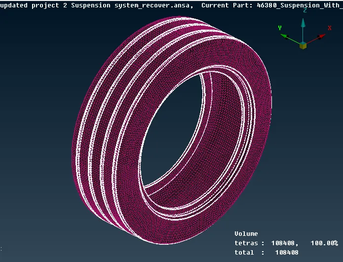
Figure 10: Volume meshing in Tire
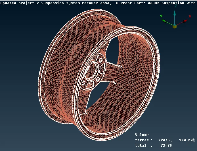
Figure 11: Volume meshing in the Rim
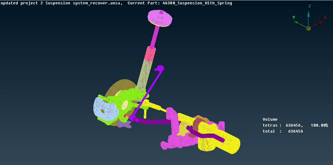
Figure 12: Volume meshing in the rest of the parts of the suspension system.
Common Quality Criteria for Tetra elements are:
|
S.No |
Quality Criteria |
Value |
|
1 |
Tet-collapse |
0.2 |
The Tetra meshed elements are viewed in the Hidden mode to check their quality.
Tetra collapse is a major quality condition of tetra elements that should be checked in the volume mesh which can be done by updating the value of 0.2 in the Solid quality criteria and the Tetra collapse can be manually fixed with the MV Free options from Grids option under Mesh module.
It is made sure that no kinks or raised dips are present in the FE model. If present, they are removed manually by using the MV Free option. The quality violating elements are remeshed again to achieve good quality by using reconstruct option.
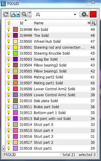
Figure 13: PID defined for Solid meshing
7. Shell meshing
Since the suspension assembly model is having uniform thickness for some parts, it is better to go for an offset method for mid surface extraction. Since the Offset is a manual method of extracting mid surface of geometry. The thickness of each face is measured to perform mid-surface extraction. The side to be offset is chosen and suitable offset distance is entered.
Topo module > Faces > Offset > Faces
The extracted mid surfaces connected with attached surfaces as viewed in original geometry using extend and intersect options.
Topo module > Faces > Extend > Target
Topo module > Faces > Intersect > Select the first and second faces
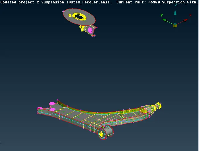
Figure 14: Mid surface, Extend and Intersect
Property ID assigning :
Here we need to create a new property ID for the mid surface and the details like thickness and other material properties to be mentioned.
Before starting with meshing the model, the Mesh Parameters and Quality criteria are to be updated.
Quality criteria for Mixed elements (For Midsurface only):
|
S.No |
Quality Criteria |
Value |
|
1 |
Target/Average length |
4 |
|
2 |
Minimum Length |
2 |
|
3 |
Maximum Length |
6 |
|
4 |
Aspect |
3 |
|
5 |
Warpage |
15 |
|
6 |
Skewness |
45 |
|
7 |
Jacobian |
0.7 |
|
8 |
Minimum Quad Angle |
45 |
|
9 |
Maximum Quad Angle |
135 |
|
10 |
Minimum Tria Angle |
30 |
|
11 |
Maximum Tria Angle |
120 |
Here the quality parameters mentioned above are entered into the Quality criteria. Here the Best meshing algorithm is used and the element type is taken as a mixed type and used the 1st order equation for solving.
Best mesh generation is a well-organized algorithm if the macro area is properly defined say in the rectangular shape, it also reduces the human efforts, features are also most perfectly captured.
To eliminate the Quality criteria errors :
- When the meshing is done on the complex area like features, we need to do some reconstruction and smooth function to properly align the element and to best quality meshing which should be rid of the quality issues.
- In the Grids module, we can find the MV Free which helps in the moving the nodes in order to overcome the quality issues
- If the area is too big we can be able to divide it into small areas lets say the macro area and can be able to do the best meshing out of it.
- Moreover, the options from the module like paste, split, swap, cut, join are used in order to do the meshing properly
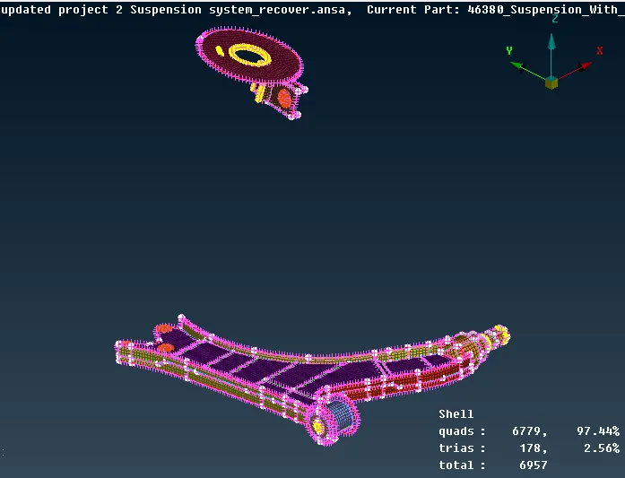
Figure 15: Shell meshing is done on the extracted mid surface
8. Modeling of Coil Spring using CBAR.
CBAR: Defines a simple beam element (CBAR) between two selected grid points, 3D-points, etc. By default, such elements are represented in ANSA as a thick blue line connecting two blue crosses.
Operations :
- Convert the Spring into a single curve which should pass through the axis of it using the following steps: Topo module > Curves > Middle
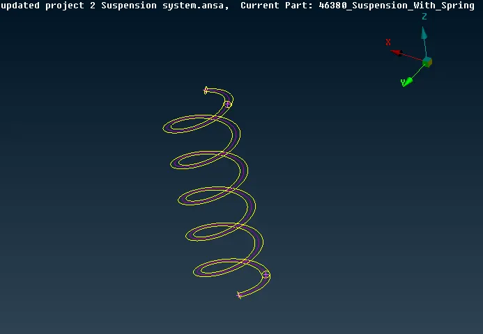
Figure 16: Curve middle option
- Using the Connect options convert the Multiple curves to a single curve and by using the following steps: Topo module > Curves > Connect > Multi
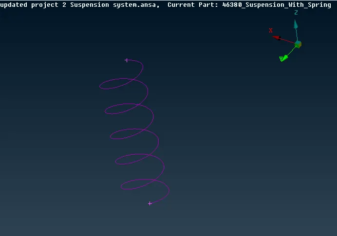
Figure 17: Curve connect option
- Now with this curve in the middle of the spring select the CBAR options from the Nastran deck.
- Select Curve (box) option from it and do a box selection on the curve
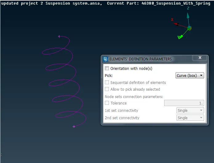
Figure 18: Curve defining for 1-D meshing
Now we need to input the average element length and after the box will as such and here we need to update the value of the diameter so that the area automatically calculated and PBAR PID is also created.
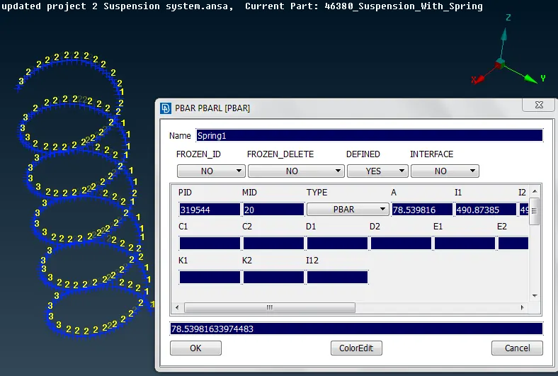
Figure 19: Value inputted for view in 3D
If we select the Line Elements Cross-section > Draw mode > as solids under the Presentation parameter we can view the 1D mesh as a 3D mesh representation.
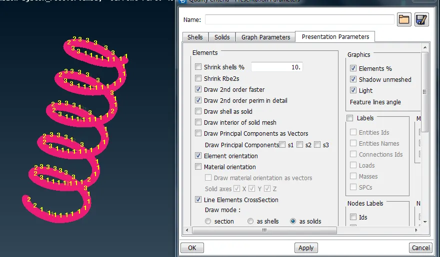
Figure 20: Spring view from 1D to solid view using Presentation parameters
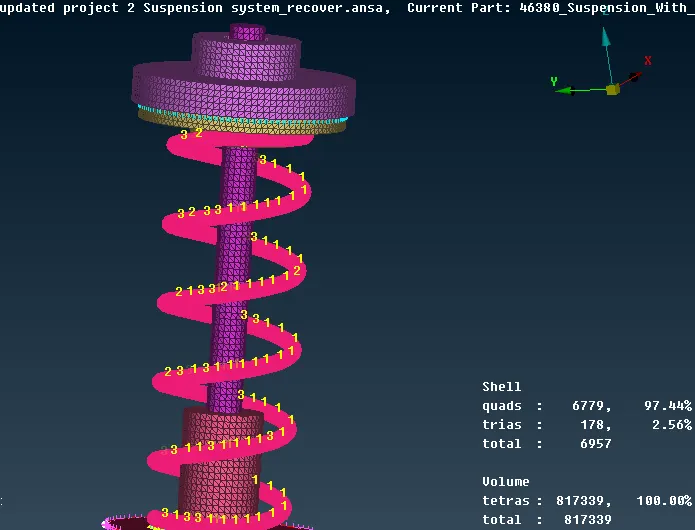
Figure 21: Spring in suspension system assembly
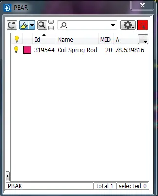
Figure 22: PID defined for 1-D Spring mesh
9. Connections:
A connector is a geometric constraint that defines how a part is connected to another part in an assembly model. Connectors are used in FE modeling to represent the kinematic conditions of a system that are physically present. Connectors in FE modelling include welds,bolts,adhesives,rigid,etc.
RBE2: An Implicit MPC (Multipoint constraint) with one independent node and several dependent nodes. Irrespective of the locations at which the dependent or slave nodes are located from the independent or master node, RBE2 restricts relative displacement between slave nodes.
General Usage:
- When RBE2 is used as a spider connection at a bolt hole, slave nodes on the hole edge will not have relative displacement and as which one cannot observe any ovalizing effect of a hole
- Consider there is a hybrid joint where components are assembled with two sub-components which are made of two different materials and those two sub-components behave integrally (i.e. behave like one ) as in this case (real scenario), we can deploy RBE2 connections effectively
In this suspension assembly, Rigid and bolt connections are used with adjacent FE macros. In all the hole regions, the connection is made using Bolts. Many nodes are selected for making cluster RBE2 bolt connections. The master nodes of two cluster RBE2 elements are connected using Two node RBE2 elements.
Two Node RBE2 (yellow in color) - Used to represent the stem of a bolt
Many Node RBE2 (blue in color) - Represents the Rigid connections
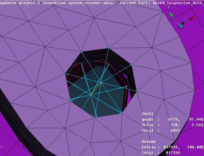
Figure 23: Bolt and Nut representation
In the above figure, the many nodes RBE2 representation is shown in blue color and the two-node RBE2 is shown in yellow color.
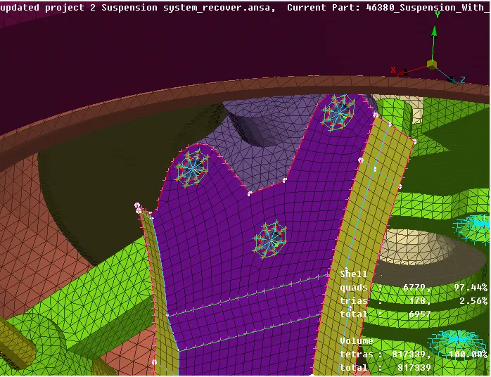
Figure 24: Bolt with washer representation
Cluster Represents the Rigid connections as shown below:
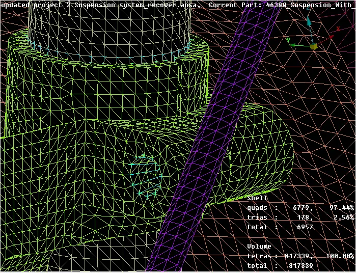
Figure 25: The Rigid connection shown between the steering knuckle and Strut part
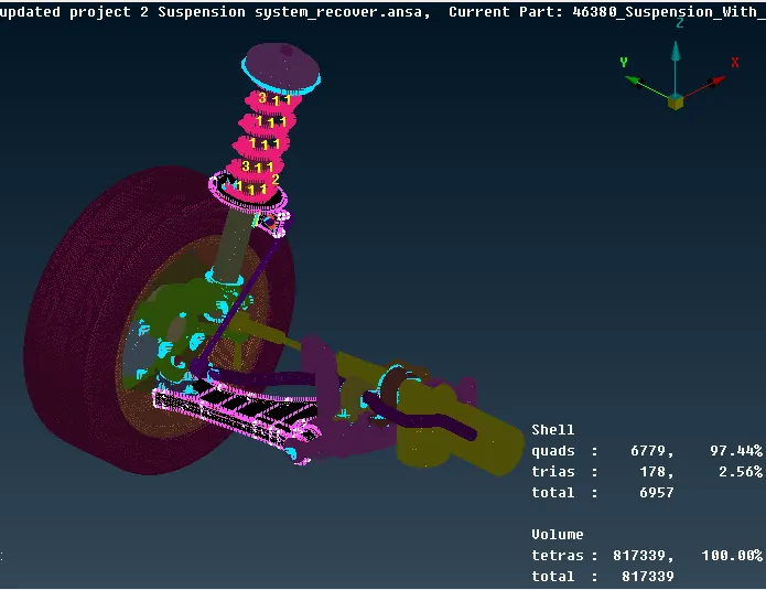
Figure 26: Suspension system in Shadow view
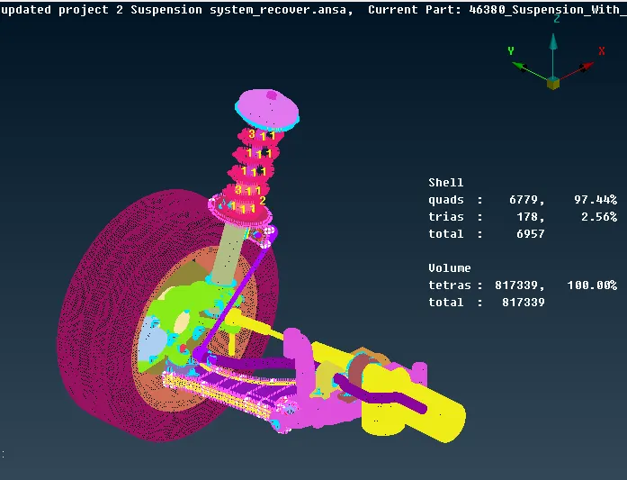
Figure 27: Suspension system in Hidden view
10. Transform Option
After all the meshing and connections have done, performed symmetry on the model to have a complete picture of the suspension system Transform [COPY]: This function is used to Symmetry or Mirror selected entities (Faces, Points, Elements, etc).
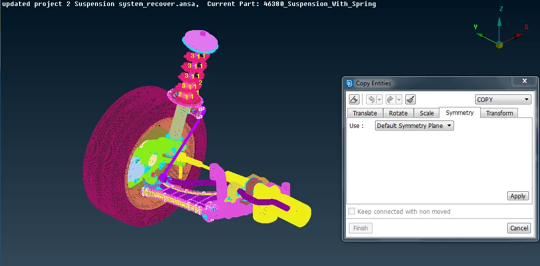
Figure 28: Steps in transform option ie, selecting Default symmetry plane
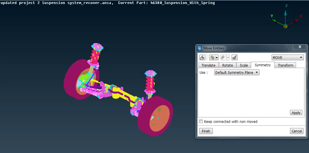
Figure 29: Steps in transform option ie, Click on Finish option
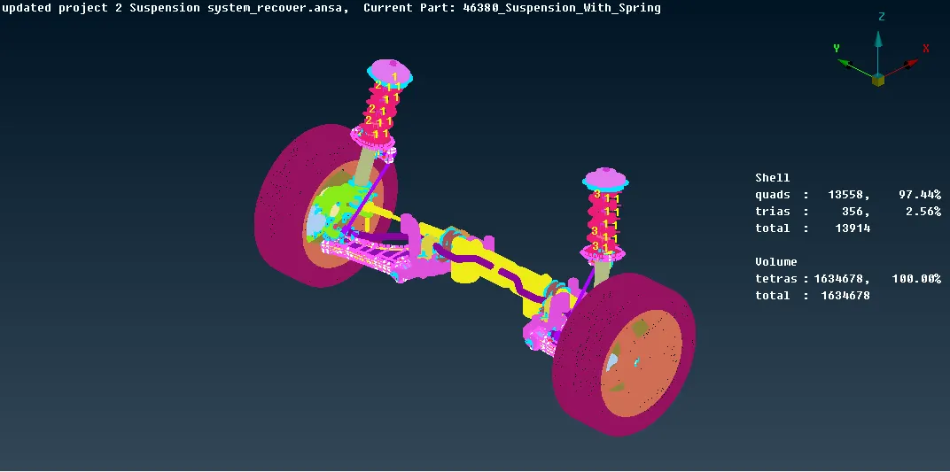
Figure 30: Transform option implemented
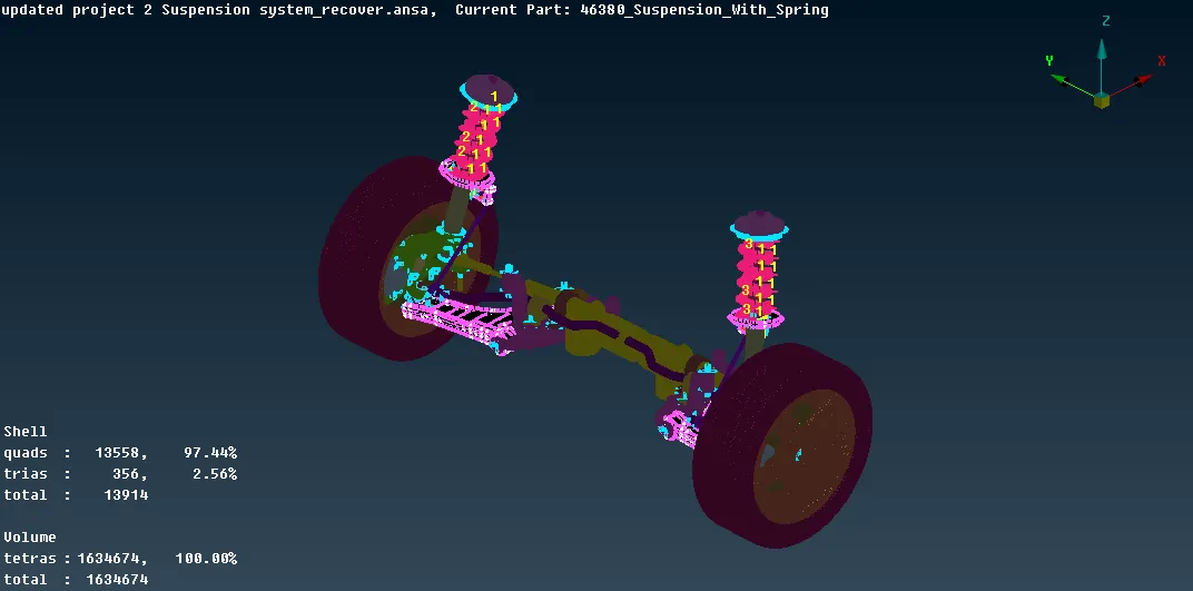
Figure 31: Full assembly view
Learning outcomes:
- Fixed the geometrical errors in Ansa by manually.
- Learned to extract the mid surface for the component.
- Got the idea to assign the property and material specification to the component.
- Studied to do meshing according to the quality criteria.
- Learned to use Volume mesh and understood the facts behind Tetra FEM and Tetra Rapid
- Studied about structural and un-structural mesh.
- Learned to remove the tetra collapse from the volume mesh and studied to move kinks or raised dips from the volume mesh
- Studied different types of connections and respective steps to do it in connection manager options (automatic connection) and also to deploy connections manually
- Two Node RBE2 - Used to represent the stem of a bolt
- Many Node RBE2 - Represents the Rigid connections/cluster representation
- Used the transform option to do meshing effectively and saved much time.
Conclusion:
Thus, the components of the suspension model are meshed with 1-D, 2-D (shell) and 3-D(tetra) elements according to quality criteria and also implemented connections in the required areas
From this project learned about the pre-processing steps that can be performed in ANSA which includes
- Ansa GUI
- Importing the model
- Geometry cleanup
- Mid surface extraction
- Assigning PIDs and Materials,
- Manual and auto meshing
- 1D meshing
- 2D/ Shell meshing
- Shell meshing for 3-D meshing
- Volume/ 3D meshing
- Quality criteria
- Works on Off-elements
- Connections
- Transformation.
Link for accessing the Suspension model is provided below:
https://drive.google.com/drive/folders/1gSQY1qYtY1uQIQ0mGn1pLvUMjYN94JtS?usp=sharing