Week - 3 Drop test Challenge
Aim: To Setup the mobile phone model for drop test using LS-Dyna
Objective:
1. To Material creation as per requirement for the different parts.
2. To section creation for solid and shell.
3. To define for Part such as material and section ID.
4. To create Boundary conditions such as construction.
5, To define Contact definition for phone and plate
6. To create Velocity which will assign to the phone.
7. To define the Control keyword so that we will control simulation like time of simulation, printing results every defined time etc.
Introduction on Finite Element Analysis:
The finite element method is a numerical technique for obtaining approximate solutions to a wide variety of engineering problems. FEA (Finite Element Analysis) is done in three phases.
1. Pre-processing
2. Solution
3. post-Processing
Drop test: The most common failure of cellular phones is probably the impact due to accidental drop, so the manufacturers aim to develop products that are impact resistant and can survive the drop test from specific height. Both physical test and finite element (FE) simulation are employed in the industry at different stages. At the design stage, FE method plays a more important role since actual drop test can only be conducted at the end of design cycle and provides little feedback to improve the design. The FE simulation will help designers understand how components interact in the assembly and how the failure mode and mechanism is developed under the impact loading[1].
Procedure:
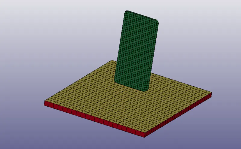
1. Import file.k: In order to open a file which is a keyword file in .k file type by file>open>LS-DYNA keyword file. In figure 1.1 and 1.2 shows the imported file.
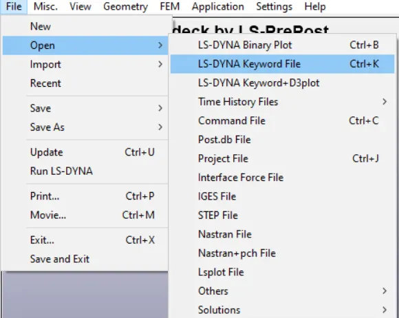
Fig.1.1: Path
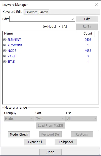
Also we can see that Keywords used in the imported file (ELEMENTS, KEYWORDS,NODE,PART,TITLE) Show in the figure 1.3.
Modeling in LS dyna
2. Creating Boundary : In order to run model we need boundary condition such as constraints and initial parameters such as velocity etc, so to create fixed plate where the phone is going to impact steps
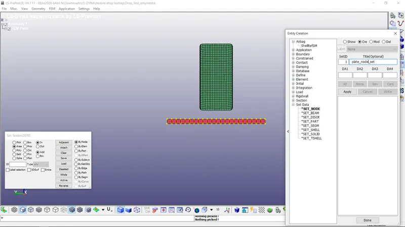
a. first create a node set ID. so that we can select that node set ID(NSID) while creating a single point constraint or velocity in this case. (Model and Part>Create(Cre)>Set> set node) similarly for phone
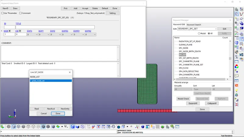
b. Create Boundary by (Model and Part>Boundary(all)>SPC) select NSID and press accept.
3. Material Creation: For every part the material is necessary in order to run simulation. also the unit system with we have to input data.
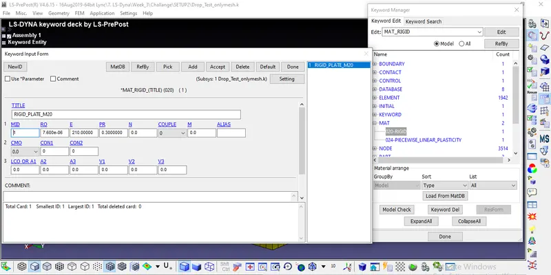
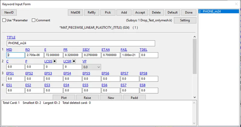
a. Here the unit system is kg-mm-ms, all the data which is input must be in same unit system.
b. Create material for a plate which is rigid. and for phone here considered as aluminium.((Model and Part>MAT(all)>020_rigid(plate ) and 024_picewise_linear_plasticity)
4. Section Keyword: In order to distinguish b/w the type of element we have to define the section keyword. for shell and solid
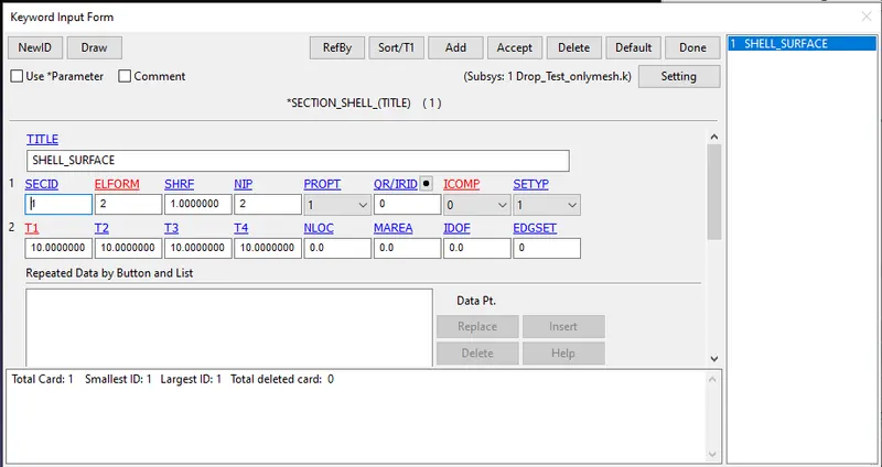
a. Section is created by (Model and Part>section(all)>shell). here we have to define thickness and type of element formulation here it's not important because all nodes are fixed in all direction so there is no element undergo displacement
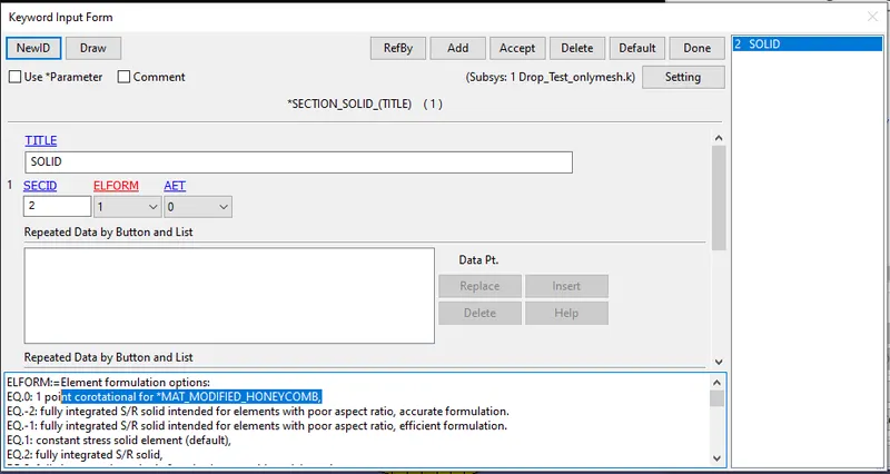
b. Section is created by (Model and Part>section(all)>solid).
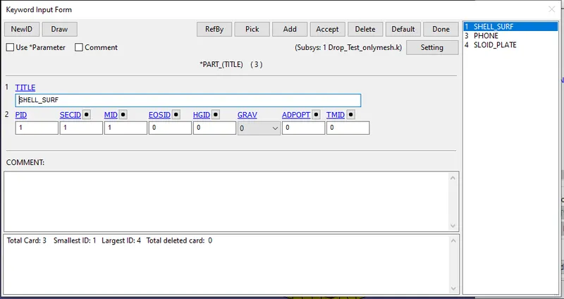
5. Assigning Material and section: one done with Material and section we can assign those data to the parts by directly clicking on part in (Model and Part>part) so we can see part list and each part has the option to select for Section ID and MATID.
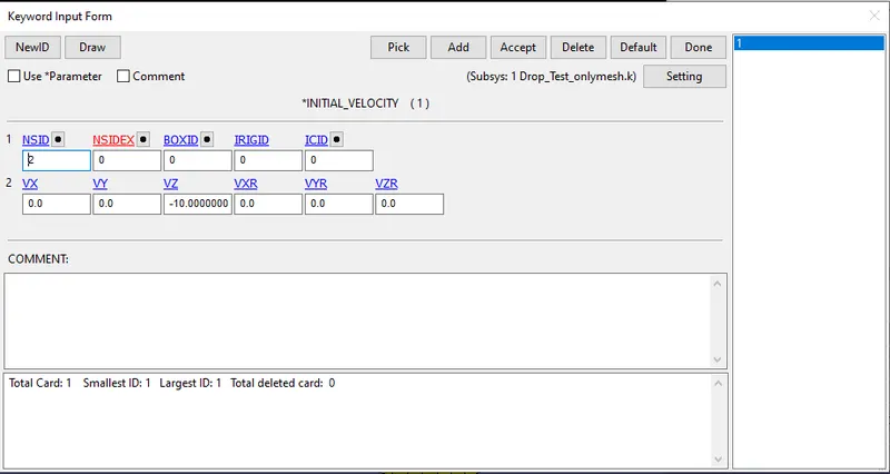
6. Initial velocity: In order to move the phone twords plate we are assuming the velocity of 10 mm/ms in negative direction. here select the node set and input velocity in which direction it should move.
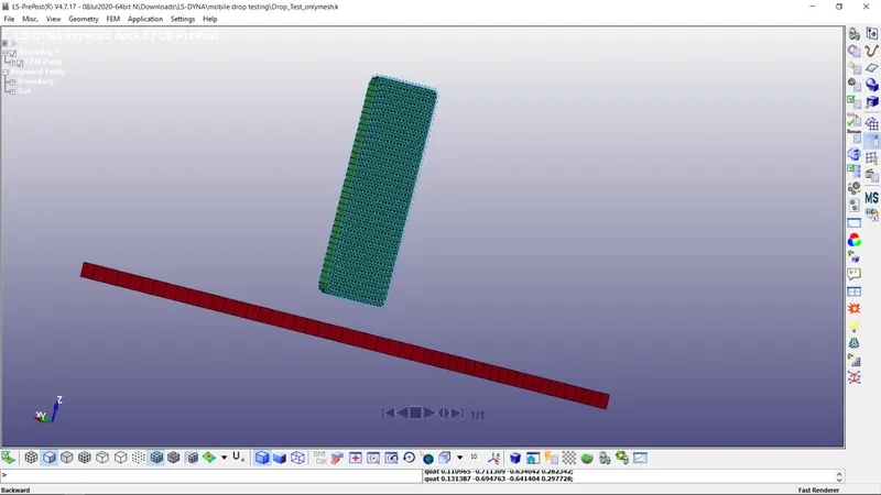
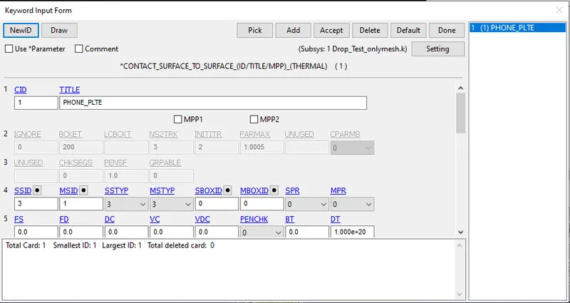
7. Define Contact: In order to impact take place b/w phone and plate there should be contact definition or else phone will simply pass through plate.
here all phone nodes are slave and all plate nodes are master nodes. we have so many options to select the by nodes or parts or sets etc.
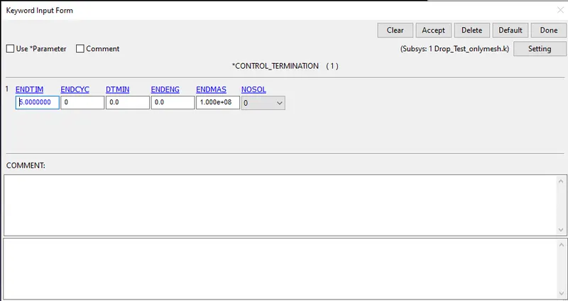
8. Control Keyword: The keyword control cards are optional and can be used to change defaults activate solution options such as mass scaling adaptive remeshing and an implicit solution however it is advisable to define the CONTROL_TERMINATION card. This key word is used to control simulation by time, 5ms
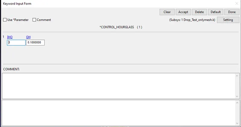
Hourglass is the defined as deformation occurs with out strain.
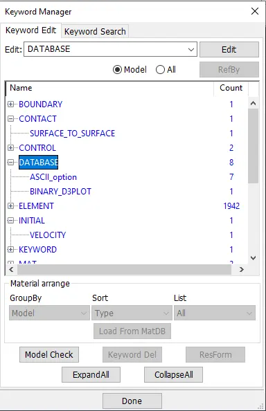
9. Output Request: Using data base pannel we can request such as animation file energy data,contact forces etc.
BINARY3DPLOT - The complete state dump interval as given in *DATABASE_BINARY_D3PLOT serves as the time step to be used in the material model driver run. Plotting information is saved in core for the interactive plotting phase.
ASCII_option- This option is used to reade the data of following
ELOUT - This latter option will output all integration point data or extrapolated data to the connectivity nodes in a file call eloutdet.
GLSTAT - Reade the energy like KE, PE, IE
MATSUM - Every material part energy due to deformation
RCFORCE - contact force b/w them
SLEOUT - sliding force due to contact
SPCFORCE - single point contact force.
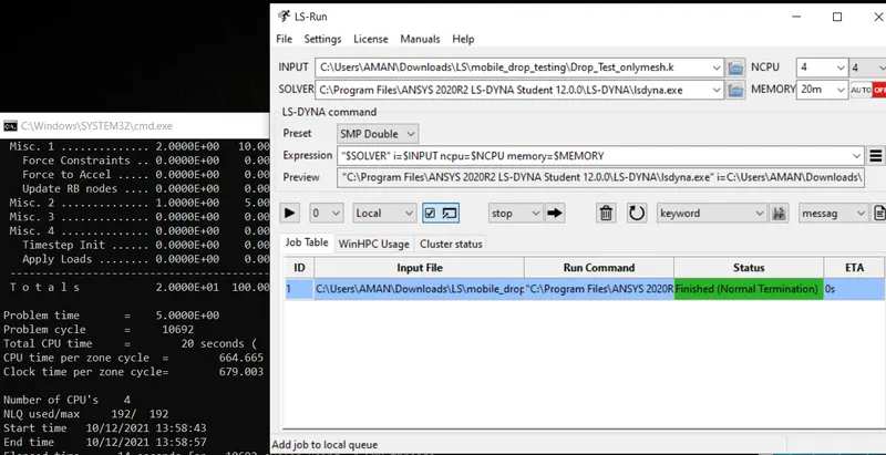
after setting tun simulation.
Results: Setup the mobile phone model for drop test using LS-Dyna and simulating the same is done.
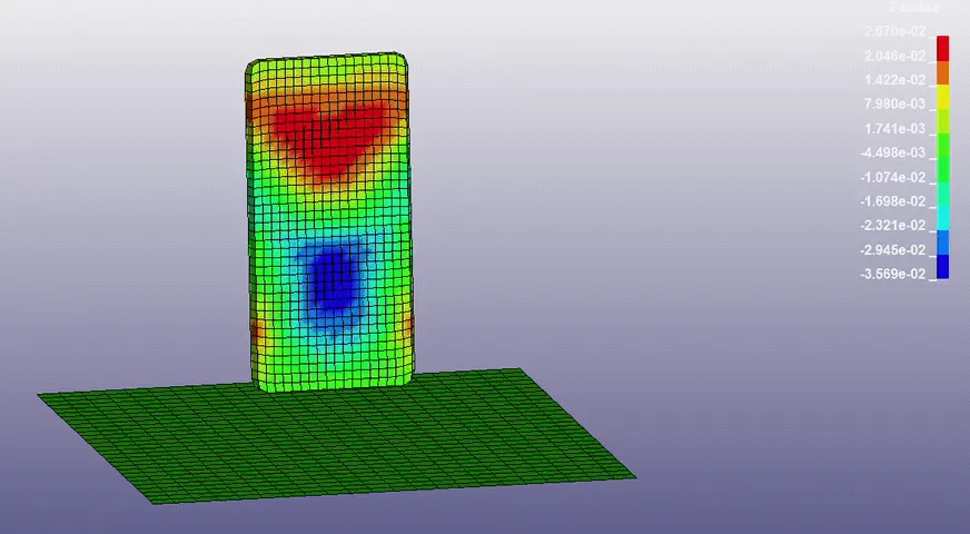
From the image bolow we can see due to impact at the time of contact with plate the maximum Stress (1.957e-1) is produces.
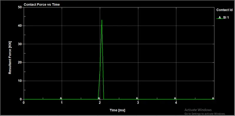
1. At initially before hitting plate , there is zoro contact force, once the phone hits the plate the contact force starts building and reaches maximum contact force
3. After that rigid wall forces are droping down beacuse velocity droping, this is due to rigid wall.at time 2.1ms we can see max force.
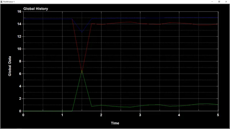
1. Initially the velocity is maximum so the Kinetic energy is maximum. when impact takes place the KE is absorbed by part, so that KE is decreasing and internal energy is increasing.
2. At the time of contact the suddent decreasing in KE and increasing in IE. Total Energy varies as per TE = IE-KE
3. Once deformation reaches max, due to PLAT wall stops velocity TO ZERO and rebound back with some velocity so same time the KE increasing,