Week 3 Challenge : CFD meshing on Turbocharger
OBJECTIVE:
For the given model, check for the geometrical errors to make appropriate volumes. Create and assign PIDs. Perform surface mesh with the given target lengths as per PIDs:
- Blade stage-1 = 1 mm
- Blade stage-2 = 1 mm
- Impeller = 2 mm
- Shaft rotor = 1 mm
- Turbo casing = 5 mm
- Compressor casing = 5 mm
- Inlet casing cover = 5 mm
Perform Volumetric mesh for the required volumes. Write a detailed report on your surface meshing & Volume meshing process.
PROCEDURE:
We have the following geometry of a turbocharger:
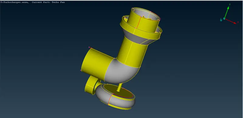
Even on the first look, we can see some red single cons. The first step is always topological cleanup and fixing the geometry.
TOPOLOGICAL CLEANUP:
Before we move on to solving these errors we turn on the PID view to check any discrepancies:
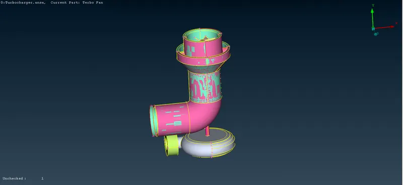
These multi-coloured striped regions show the overlapped surfaces, we will first fix these by deleting the unnecessary surfaces.
Once we are done with removing the overlapped surface, we move on to doing geometric check:
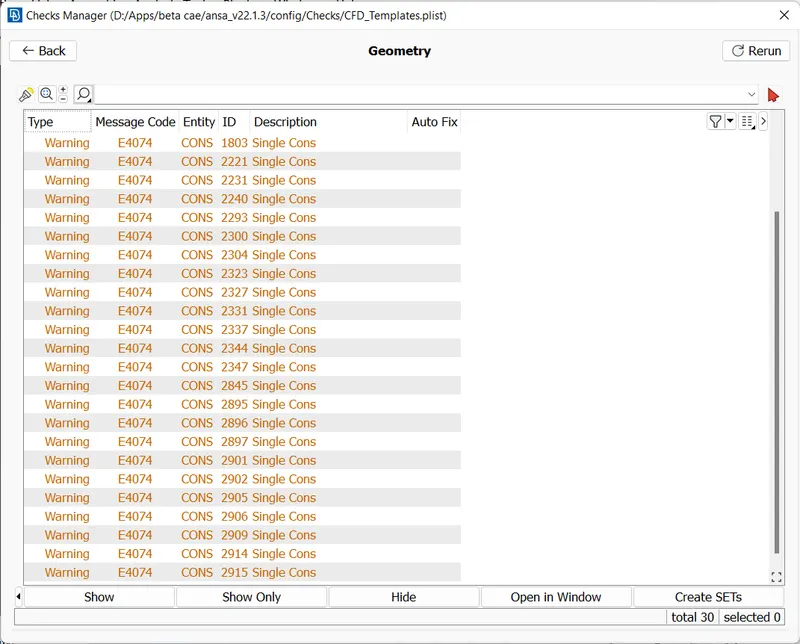
Multiple Single cons show up, we will now use the show only option to isolate the single con and neighbour option to see the nearby geometry.
Once we have taken care of all these single cons, we have to make sure that our geometry does not have open regions:
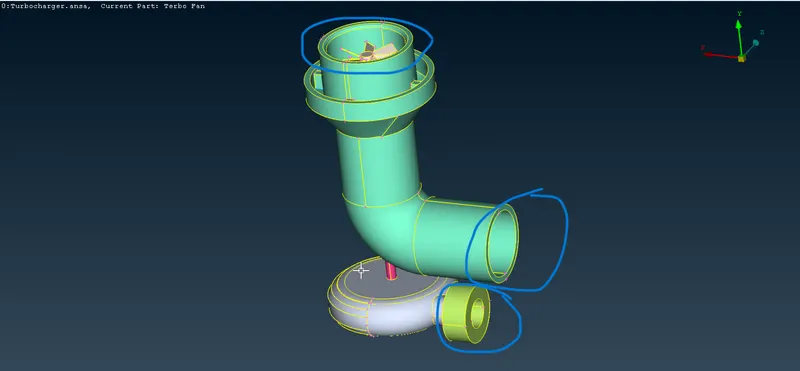
We will look for any other openings in geometry besides these obvious ones and close them:
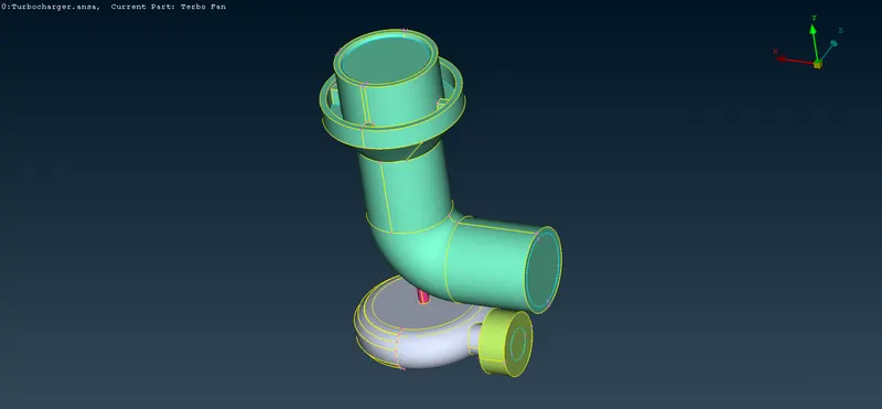
Once done with all the changes we run geometry check again to see if we missed any errors:
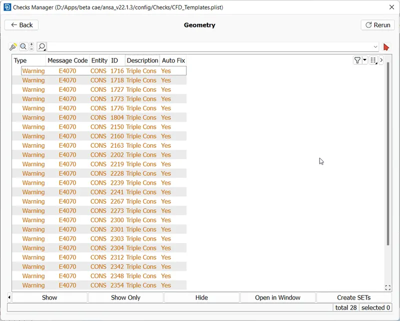
Most of the errors have been fixed and only the triple cons warning remains, we will check if the triple cons are genuine or redundant and then move on to the next step.
PID SEGREGATION:
Next, we segregate the default PIDs into actual components to clearly identify various parts:
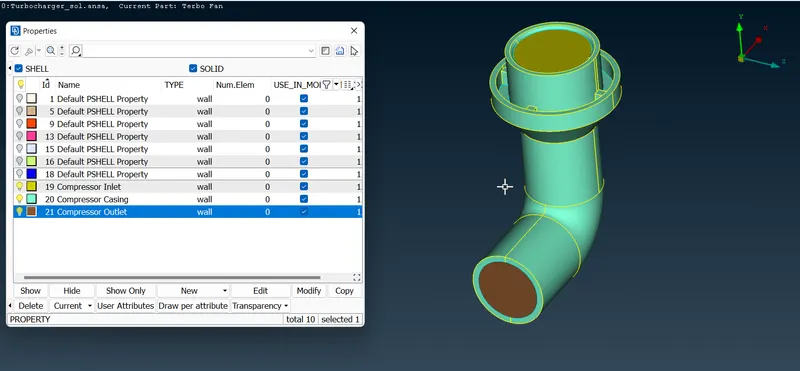
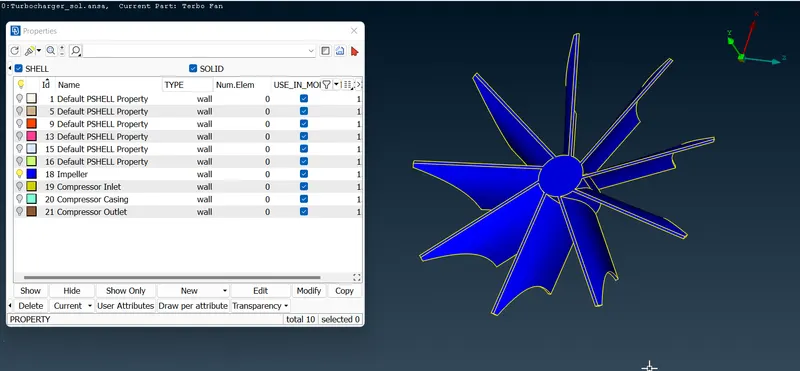
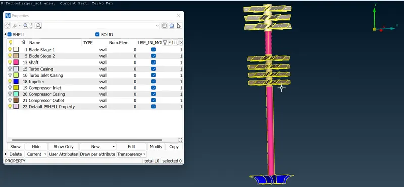
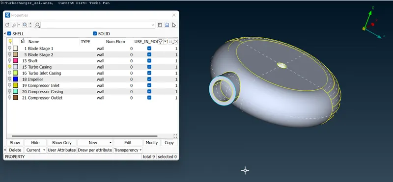
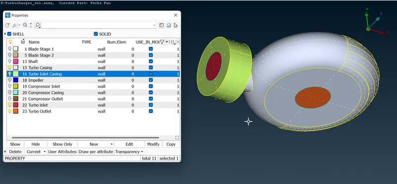
SURFACE MESHING:
We will mesh the respective PIDs with the given Mesh length.
Blade Stage 1 - 1 mm:
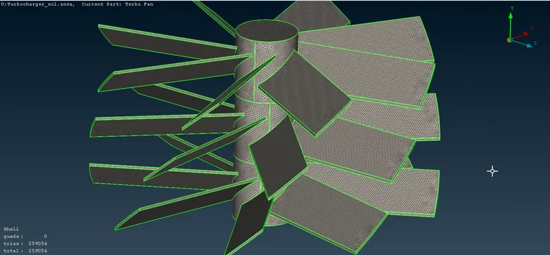
Blade Stage 2 - 1mm:
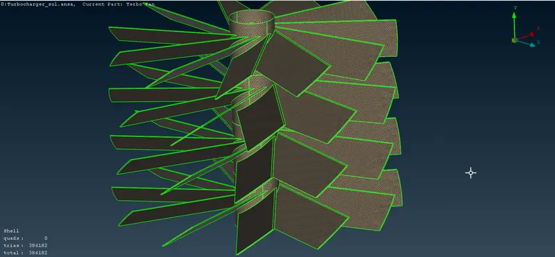
Impeller - 2 mm:
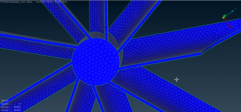
Shaft - 1 mm:
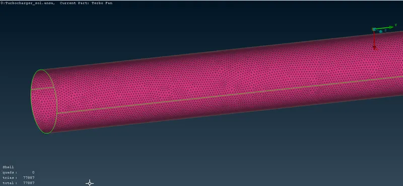
An important issue that occurs here is where places with 2 different element mesh meet overlap and one region loses the mesh near that place as in this example of shaft and propeller:
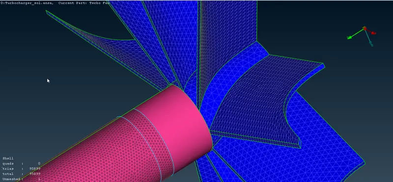
To fix this we need to remesh the region with a variable element length (1-2 in this case) for a smooth transition of size:
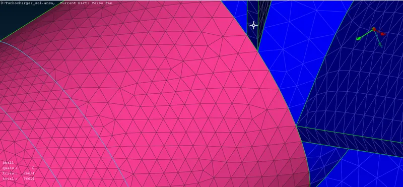
Similarly, we use the Spacing option to give variable mesh size.
Turbo Casing - 5 mm: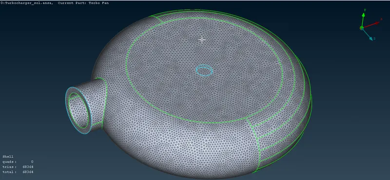
Compressor Casing - 5mm:
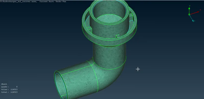
Inlet Casing Cover - 5 mm:
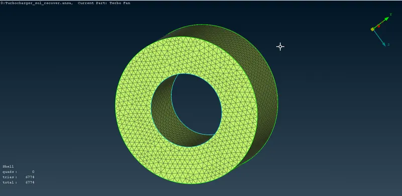
VOLUMETRIC MESH:
Using The define option under the volumetric mesh section, we can auto-detect the volumes of the model:
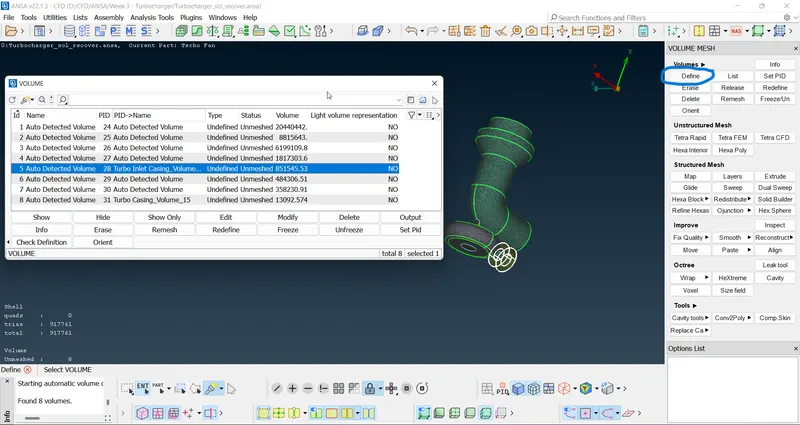
Ansa has detected 8 volumes, we need only the volumes of the hollow so we will not consider the volumes of geometry itself:
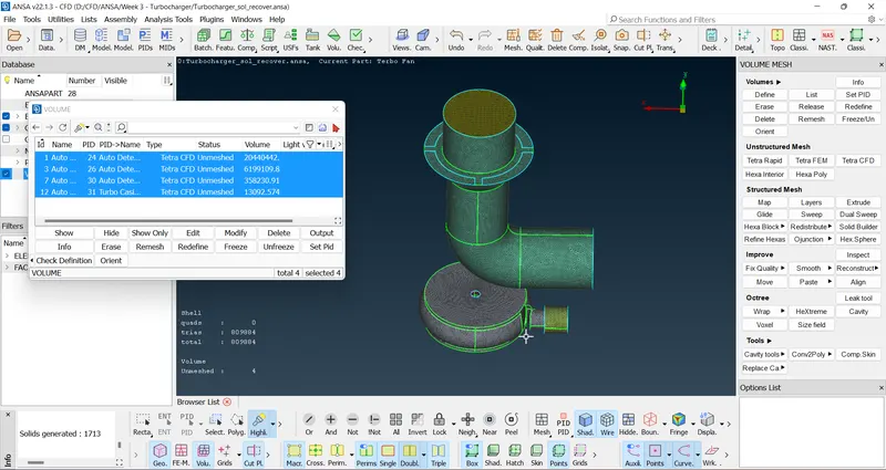
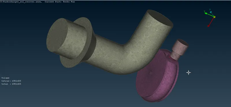
Next, we will use the remesh option and choose Tetra CFD:
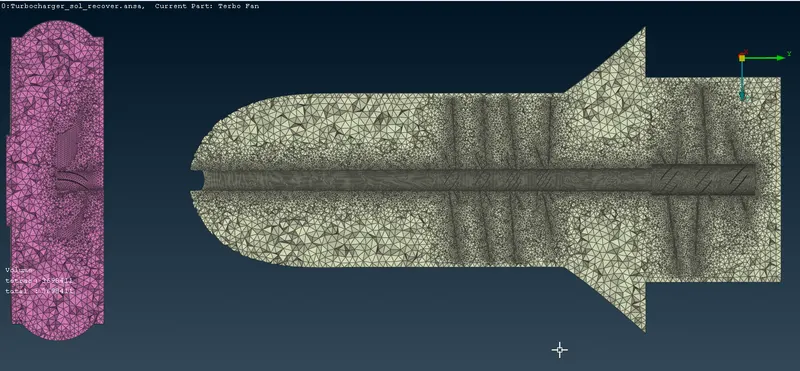
Cross-section:
CONCLUSION:
Thus, we have successfully performed volumetric meshing on the Turbocharger.