Week 3 Challenge : CFD meshing on Turbocharger
Objective:
To perform volumetric mesh for CFD analysis on a given turbocharger model
Procedure:
Topology cleanup:
The given model is imported
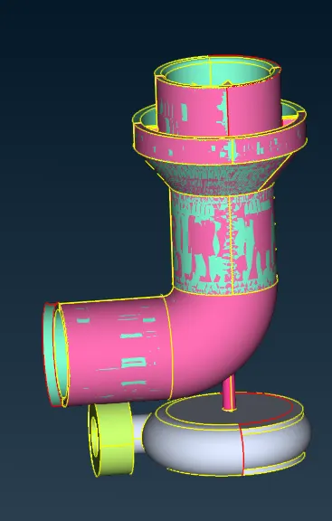
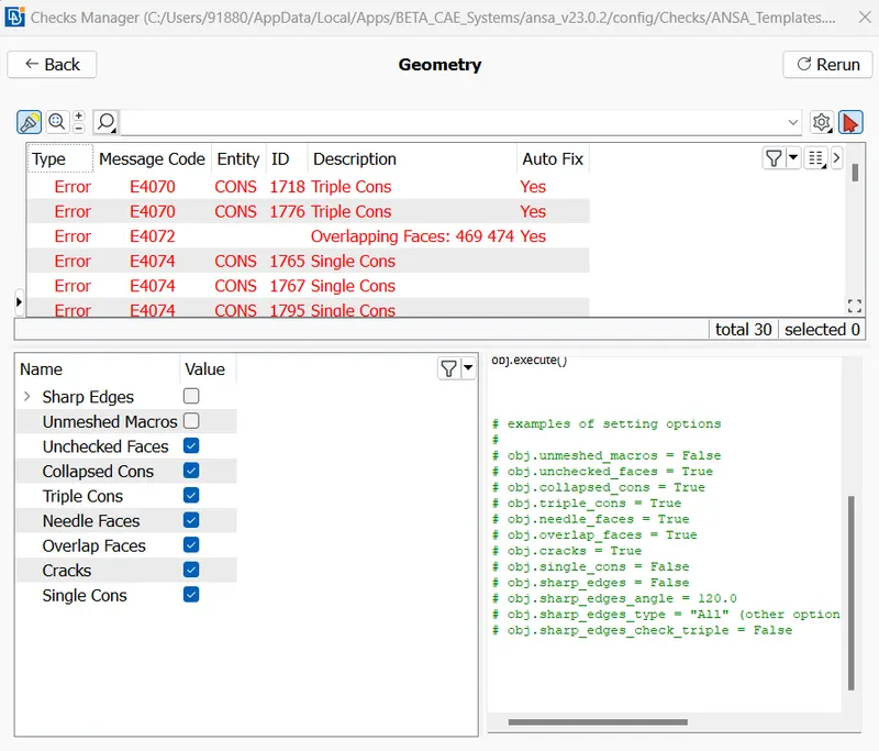
Checked geometry for errors with single cons enabled
Removed overlapped surfaces by deleting the faces
Fixed the single cons by creating a new face
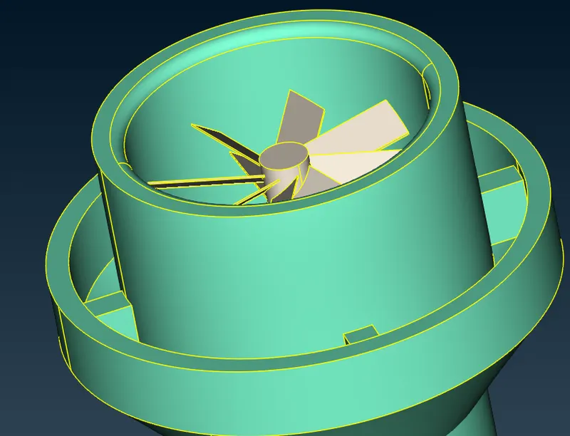
Deleted the extended surface and patched it with a new face
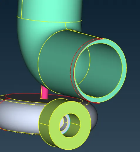
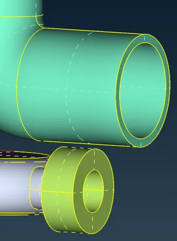
Patched this surface by creating small faces
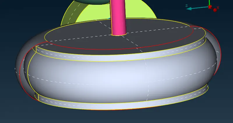
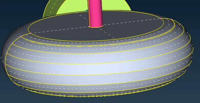
Fixed the intersection using intersect option and deleted the extended surfaces
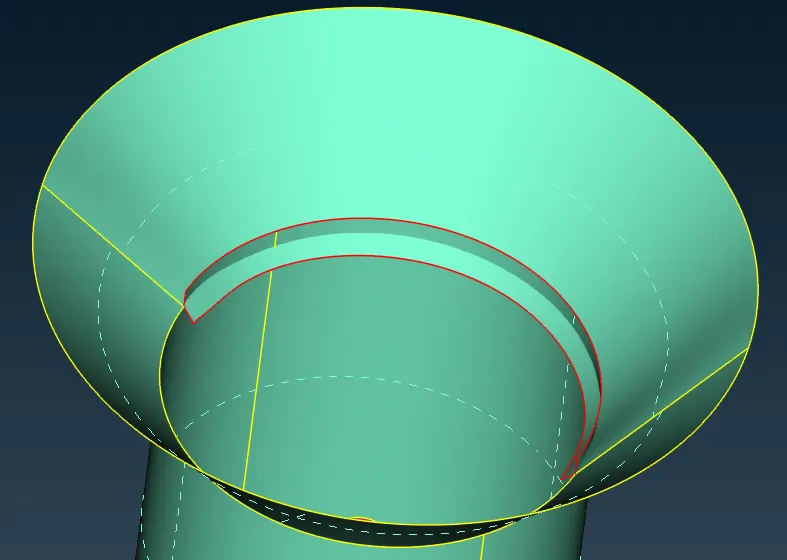
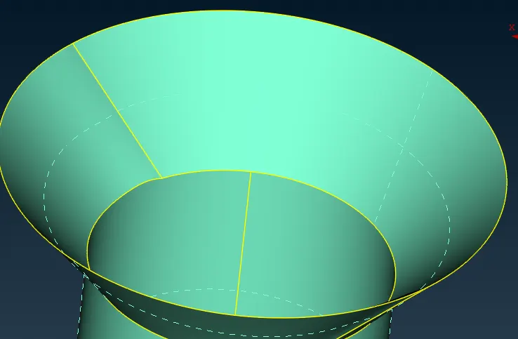
Removed the overlap by projecting the con to another surface and deleting it
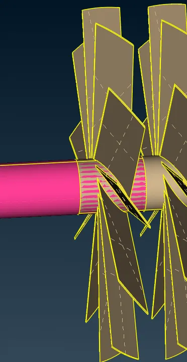
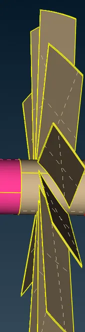
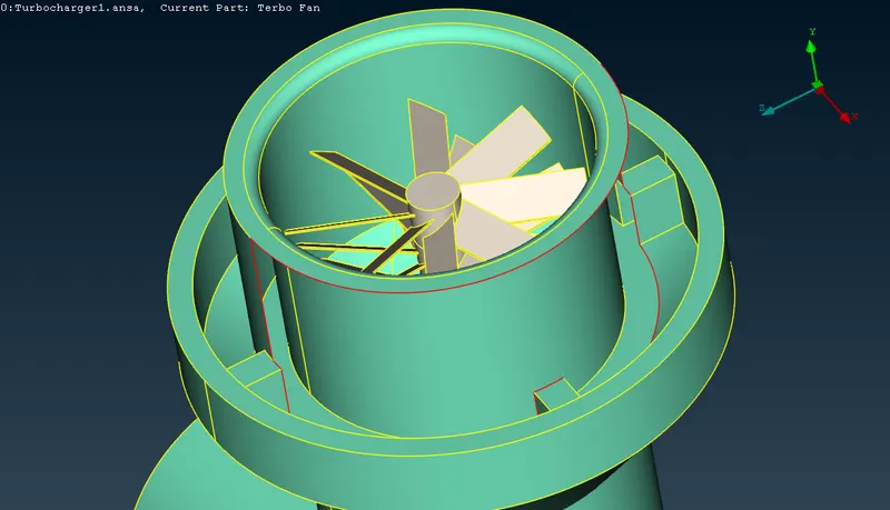
Fixed all the overlapped faces and single cons for the shaft
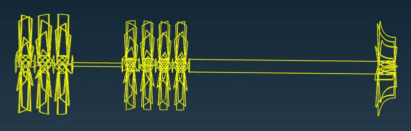
Merged whole rotor shaft into one PID
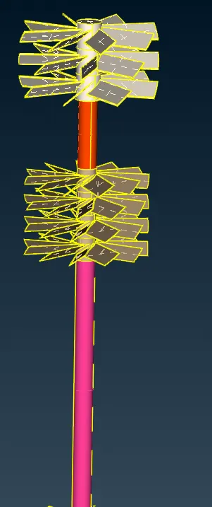
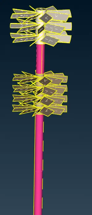
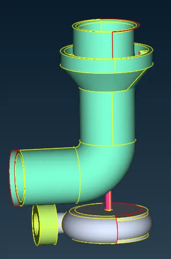
All geometry errors were fixed except necessary triple cons
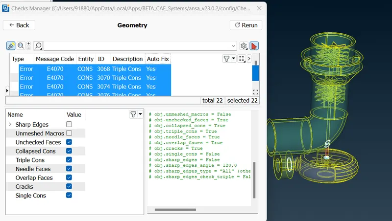
The model is closed and PID regions are created before proceeding to mesh
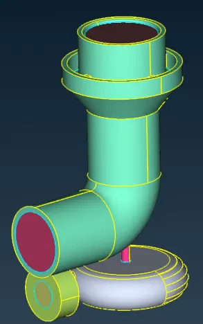
Surface meshing
All the parts have meshed with the following size
- Blade stage-1 = 1 mm
- Blade stage-2 = 1 mm
- Impeller = 2 mm
- Shaft rotor = 1 mm
- Turbo casing = 5 mm
- Compressor casing = 5 mm
- Inlet casing cover = 5 mm
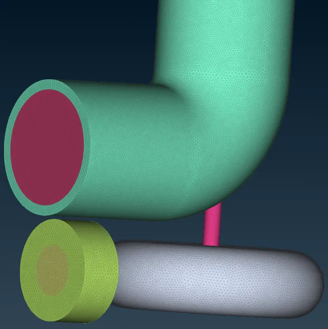
Volume meshing
Auto-detected volumes using define
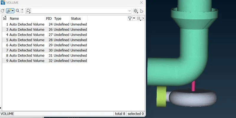
Unwanted volumes are deleted
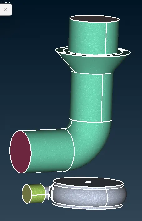
Performed volumetric mesh with element type as tetra CFD
Learning Outcomes:
- Learned to perform volumetric mesh after obtaining a 2D mesh
- Removing overlapped surfaces
- Surface meshing with different mesh lengths
Result:
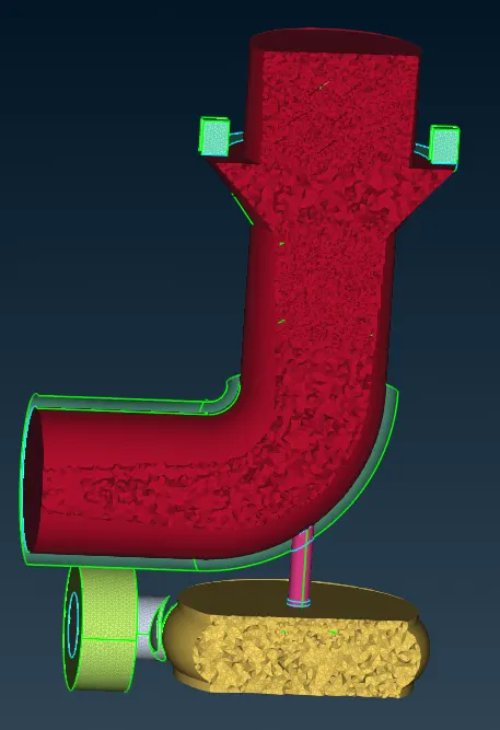
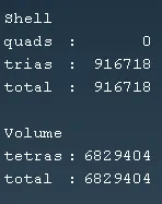
Conclusion:
The volumetric mesh helps in converting the 2D mesh into a 3D mesh, here for volumetric mesh we use tetra CFD elements which has a tetrahedral shape and is mainly useful for CFD simulations. We can see in the results the volumetric mesh follows the sizing of the surface mesh wherever we gave a small mesh size in surface is reflected in volume mesh also.