Week 3 Challenge : CFD meshing on Turbocharger
Objectives:
We document our efforts of the following preprocessing steps carried out on a geometry of turbocharger.
- Clean the topology.
- Generate surface mesh
- Generate volume mesh.
The specifcations of the element size for the surface meshing are as follows:
- Blade stage-1 = 1 mm
- Blade stage-2 = 1 mm
- Impeller = 2 mm
- Shaft rotor = 1 mm
- Turbo casing = 5 mm
- Compressor casing = 5 mm
- Inlet casing cover = 5 mm
Section 1: Topology clean-up:
Our first step would be downloading the model from the repository and then visualize it in the ANSA GUI. The following image was captured before any form of pre-processing has started.
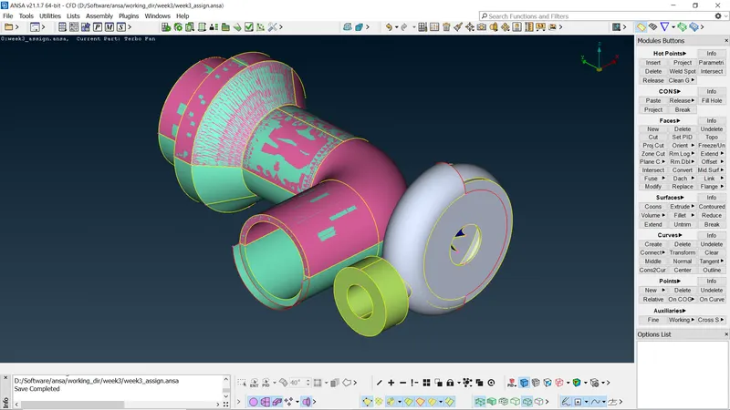
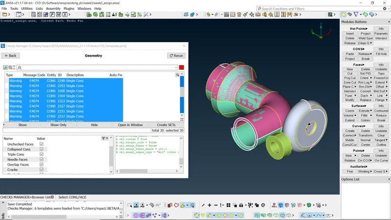
We observe that a lot of topology errors i.e. single, triple cons and glitching surfaces are present in the model. For making an exhaustive list of these errors we use the "Geometry Check" tool in the ANSA GUI. Some of the errors in the topology after we perform the checks are as follows:
After identifying these errors, we start correcting them. We skip showing the correction of all single cons, but we showcase the filling of the hole in the topology, which provides extremely poor filling only using the base edges.
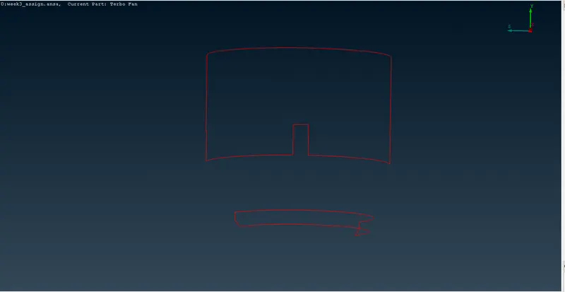
To mitigate this situation, we divide the longer edges using hotpoints using multi-project tool. The idea is to provide a "guiding hand" to the tool to fill the hole in a certain order.
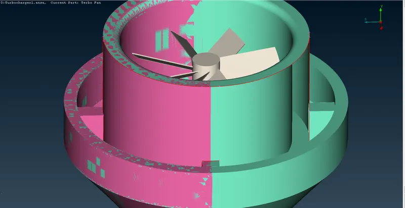
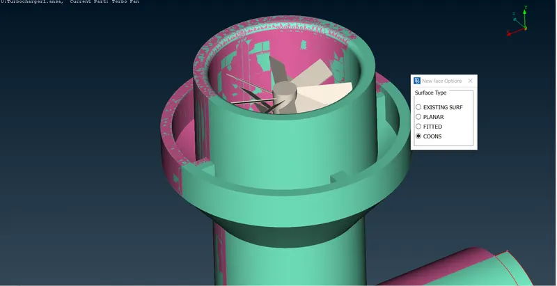
Before adding further topological corrections, we wish to solve the glitches "multiple surfaces in the same location" for our sanity. For this, we identify triple cons and try to recity them. We note that not all triple cons are errors, as some of them represent connection between two different volumes.
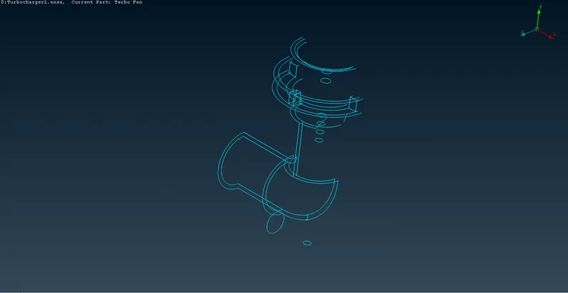
To remove these extra surfaces, we use the Delete faces tool inconjunction with the PID Region tool, to select maximum amount of contiguous volume and delete it. This is done for reducing our efforts.
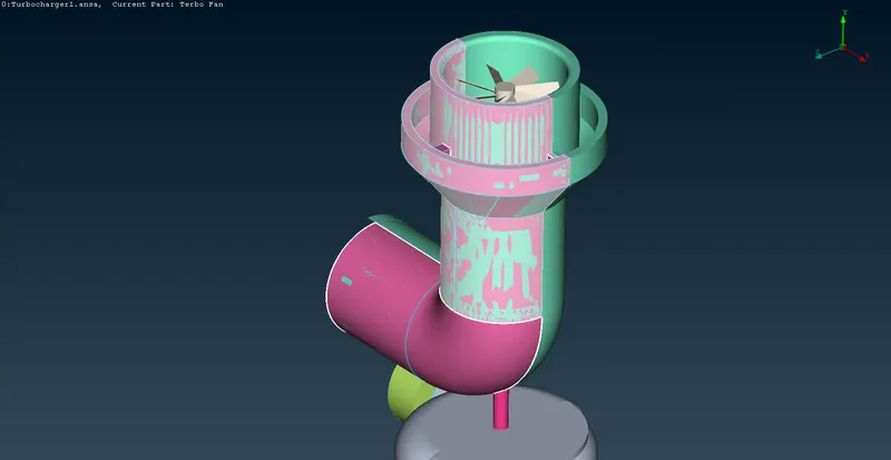
As we see in the following image, the glitches from the section which was selected has been successfully removed. We perform this steps for other triple cons without explicity showing it in this document, for the sake of brevity.
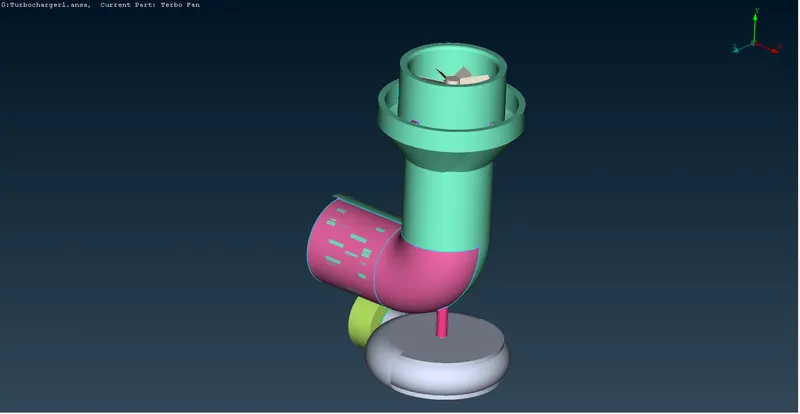
We also observe certain faces which have dimensions that do not match with their neighbors. In this case, we delete it and intentionally create a hole.
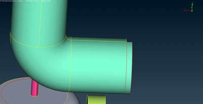
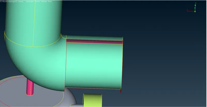
After this process, we fill the hole using the fill surface tool and so that the new surface while have the appropriate shape.
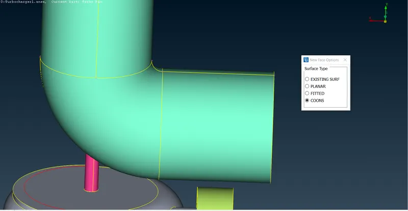
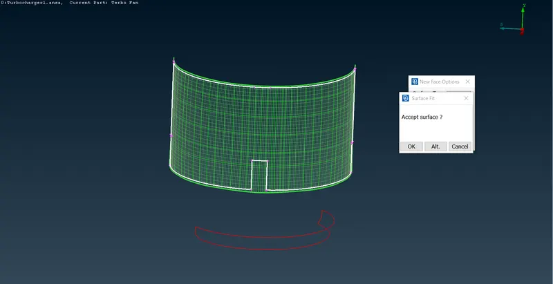
To fill the following hole, we need to again provide some form of "guidance" to the new face tool. For this, we generate several new hot points using parametric tool on the curved surfaces, so that the new surface can make a satisfactory curve to follow it.
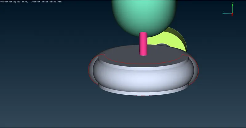
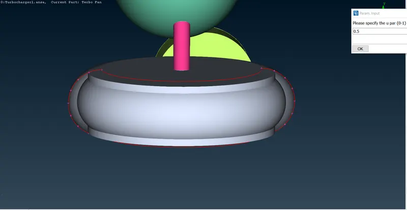
Now using these points, we create the surfaces to patch the hole.
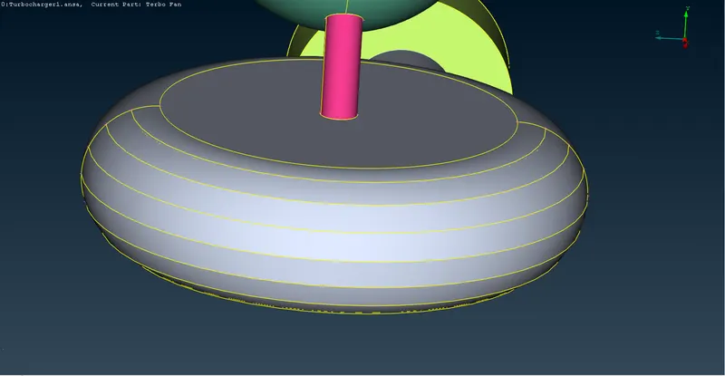
For solving the intersecting faces single edges error, we use the intersect face tool to trim the extra surface. We chose the first and second face as follows:
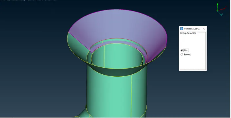
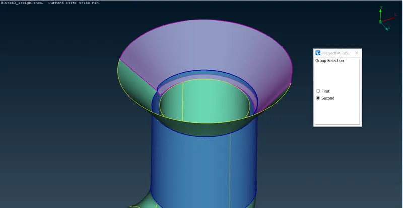
After trimming the intersecting edges, we get the desired double coons.
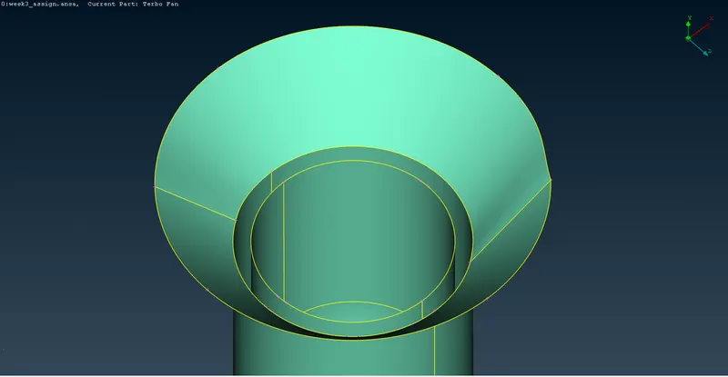
Now, we focus on the remaining triple cons of the model, particularly on the shaft that connects the compressor blades to turbine blades.
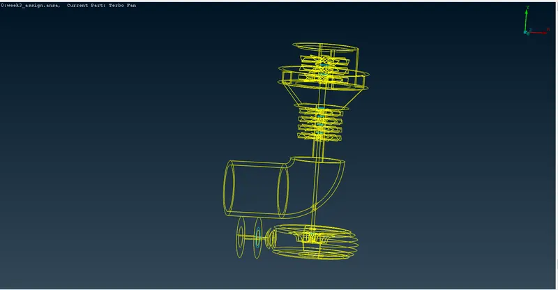
We begin mitigating this error by deleting the extra surface inside the channel to transform the triple cons to double cons.
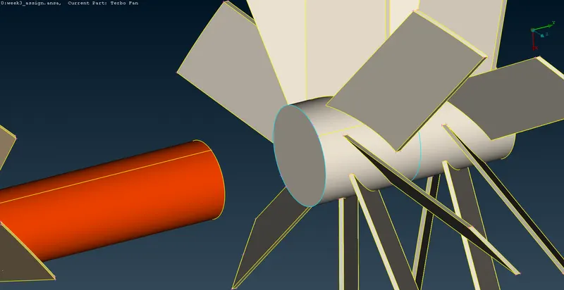
The corrected connection is as follows. we follow this same step for the rest of the triple cons which are formed because of the extra surfaces.
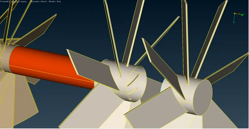
To mitigate the following triple con, which is formed because of the overlap of two surfaces as shown in the following image, we first project the cons of one surface on another and then remove the overlapping part.
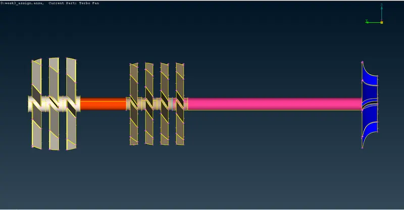
After projecting, we observe that the shaft has a limited accuracy in capturing the shaft cross-section. For this, we use the fine auxillary tool for capturing the surface with better accuracy
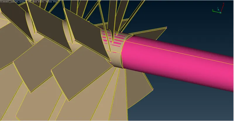
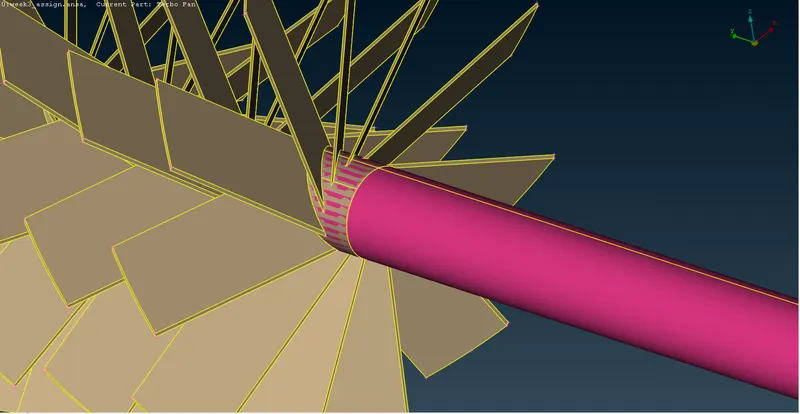
Now, we remove all the extra overlapping surfaces and get the following correct result with no glitched-put surfaces
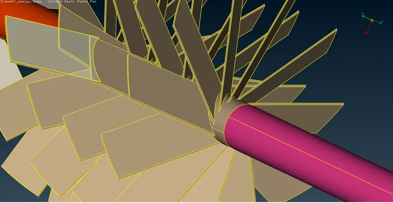
We execute geometry check for the above model, we see that there are no triple and single cons present
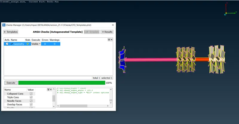
After successfully solving the errors in the entire geometry, we now close the geometry in-order to form an enclosed volume.
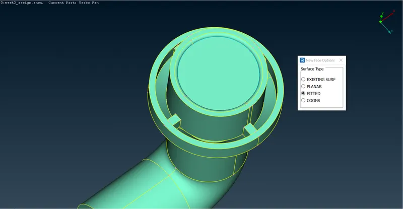
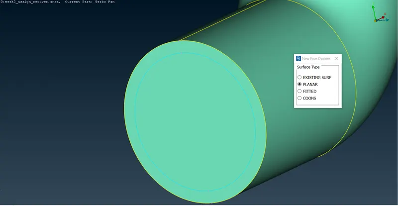
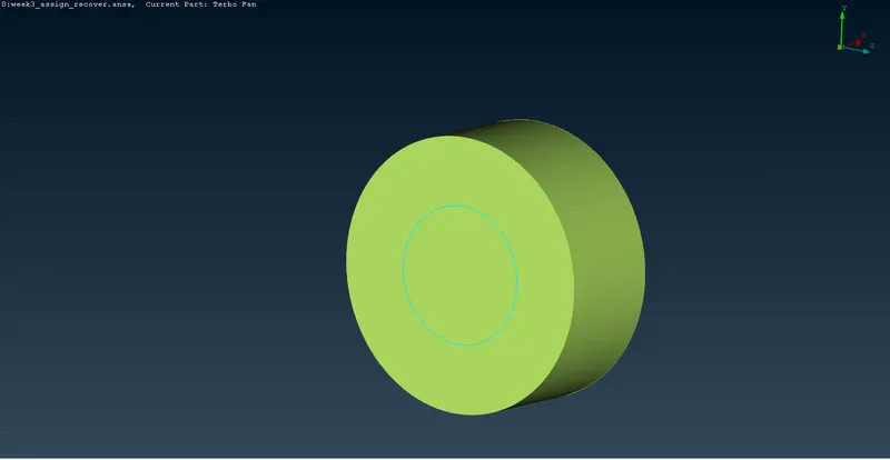
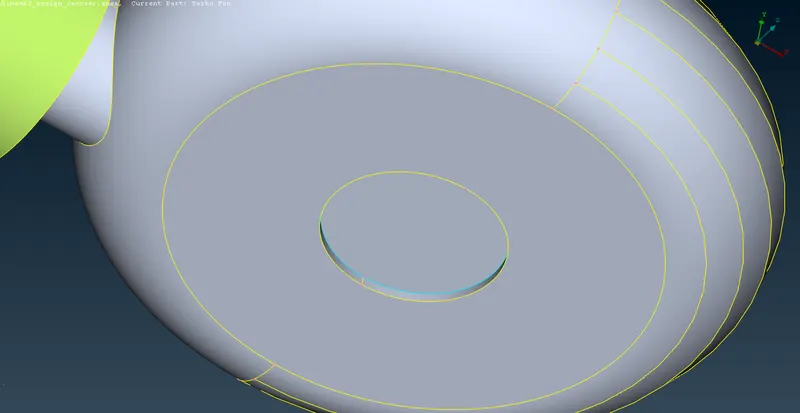
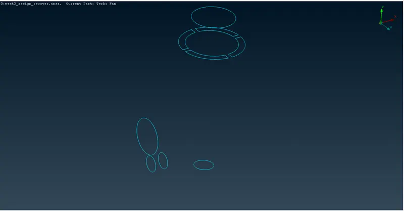
The following triple cons are acceptable as they either enclose or separate volumes.
Section 2: PID Naming:
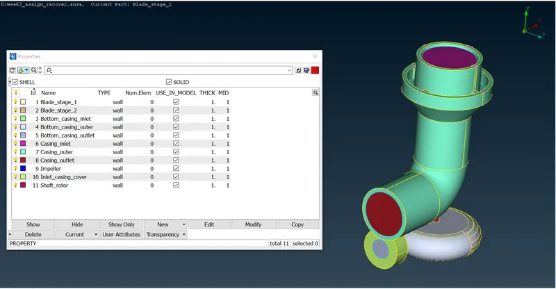
For the intent of getting a better control on the generation of surface meshes, volumes for volume meshing. We provide appropriate names based on the geometrical features observed in the model.
Section 3: Surface Meshing:
For our study, we have chosen the following dimensions for the surface mesh
- Blade stage-1 = 1 mm
- Blade stage-2 = 1 mm
- Impeller = 2 mm
- Shaft rotor = 1 mm
- Turbo casing = 5 mm
- Compressor casing = 5 mm
- Inlet casing cover = 5 mm
We first mesh the compressor casing, along with its inlets and outlets with a mesh element size 5mm. For this we use the length tool and in Mesh parameters set the min length as 3mm and max length as 7mm
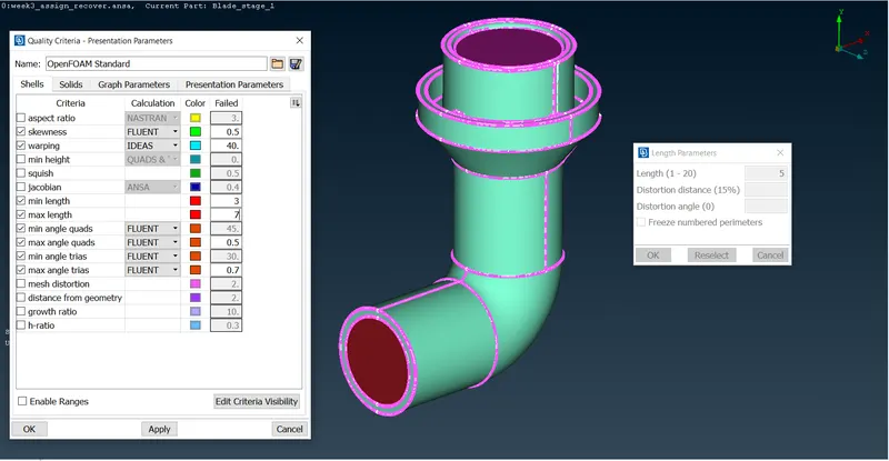
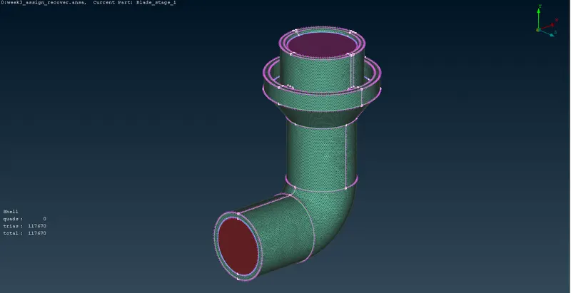
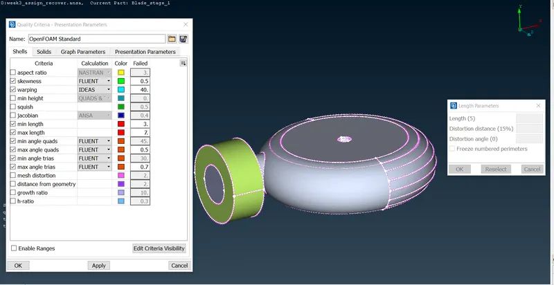
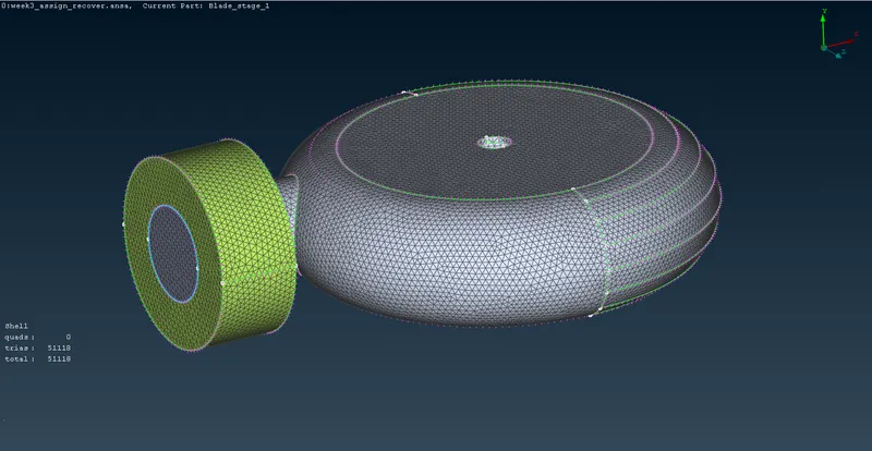
Next, we generate surface mesh for turbo casing and inlet casing with a target mesh element length of 5mm. We will follow similar procedure used for the compressor casing.
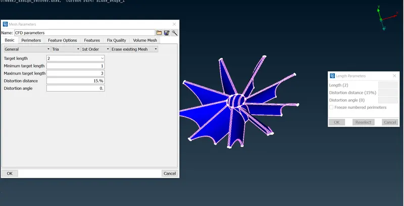
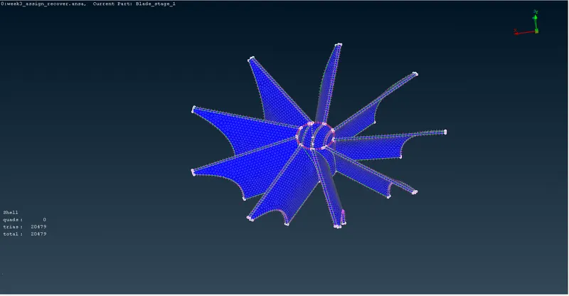
We set the mesh length for the impeller as 2mm ,and min length as 1mm and max length as 3mm in Mesh parameters.
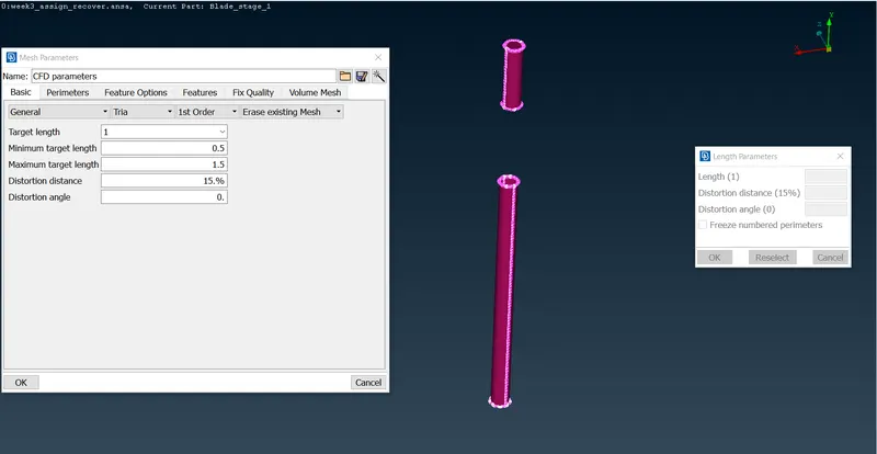
We set the mesh length for the shaft rod as 1mm ,and min length as 0.5 mm and max length as 1.5 mm in Mesh parameters.
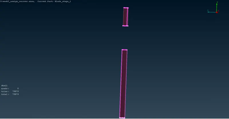
Identical to previous step, we set the mesh size for stage 1 and stage 2 blades as 1mm
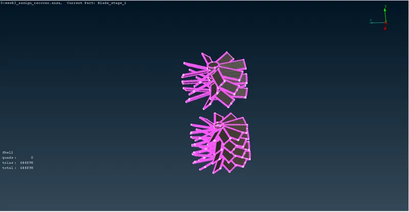
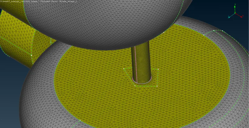
After this, we observe that certain 18 shells are unmeshed and to visualize them, we use the show only tool. We identify the source of the problem as the discrepancy between the cell length which changes from 5mm to 2mm.
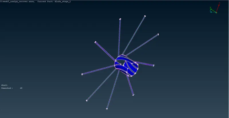
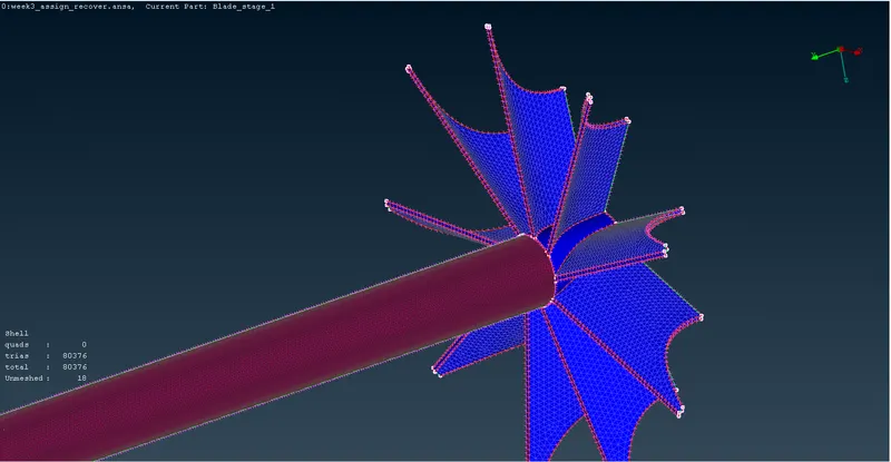
We fix the issue by fixining the mesh length to the shaft rod as 1mm, and varying the length on the parts connected to them. After doing this, we will observe that there will be adaptive growth of cell length away from the shaft.
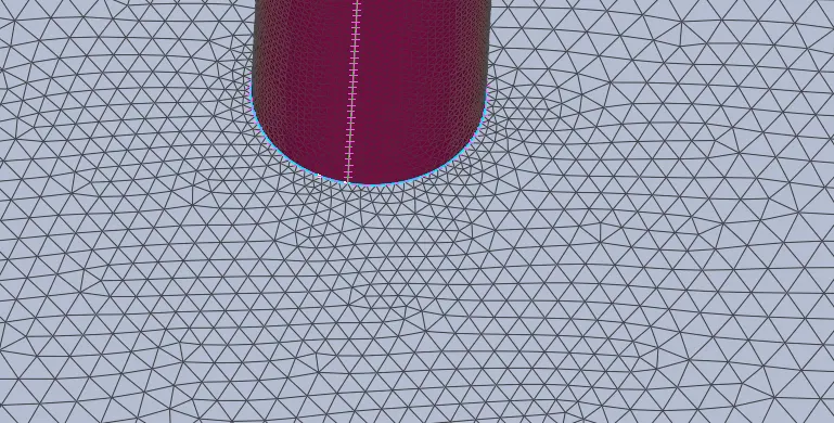
To reduce the transition region, we use the cut macro option.
Section 4: Volumetric Meshing
We first determine the volumes that will be used for building the volumetric mesh after building the surface mesh.
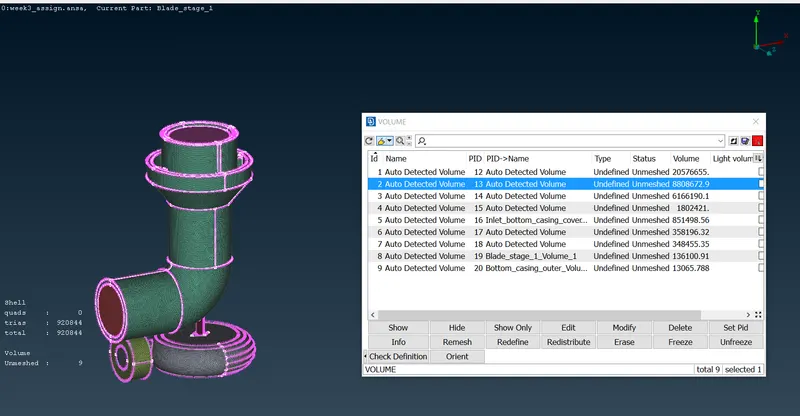
Here we will keep only those PIDs/volumes which are the part of the fluid domain.
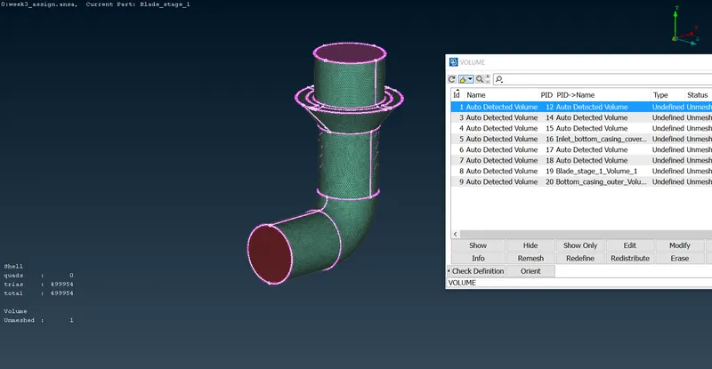
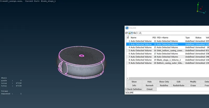
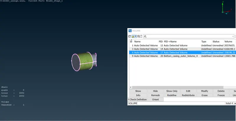
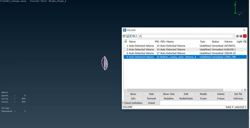
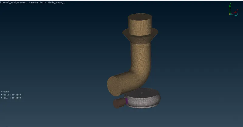
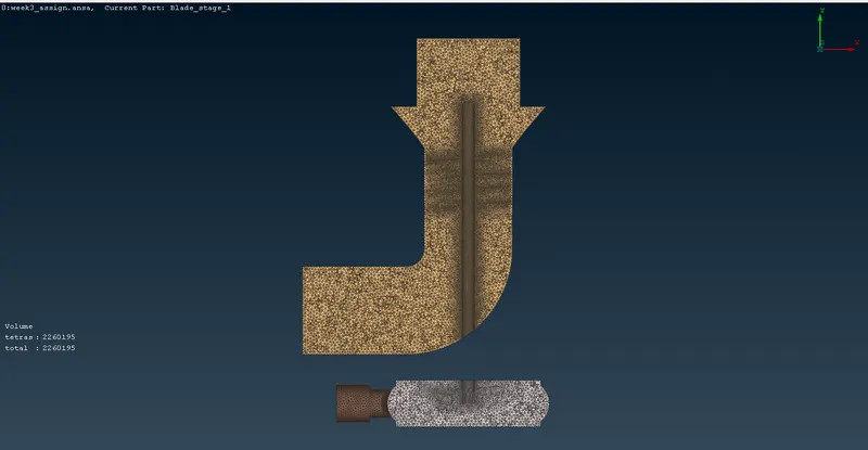
After volume meshing is completed, we see the following mesh. From the cut section view of the mesh, we can see the variation of the cell size (1-2mm to 5mm) from the blades of the compressor/turbine and shaft rod as we move away from them.
CONCLUSION:
Thus, the geometrical errors like single, double and triple con are checked and PIDs are assigned accordingly to the requirement and the surface is generated for with the given target lengths. Then volumetric meshing is performed for the volumed required successfully.