Week 3 Challenge : CFD meshing on Turbocharger
Aim:
check for the geometrical errors to make appropriate volumes. Create and assign PIDs as shown in the video. Perform surface mesh with the given target lengths as per PIDs.
- Blade stage-1 = 1 mm
- Blade stage-2 = 1 mm
- Impeller = 2 mm
- Shaft rotor = 1 mm
- Turbo casing = 5 mm
- Compressor casing = 5 mm
- Inlet casing cover = 5 mm
Procedure:
1. import .ansa file by File→Open→select file
2.for surface mesh and volumetric mesh we have to prepare model by eliminating surface errors we need to apply geometry cleanup
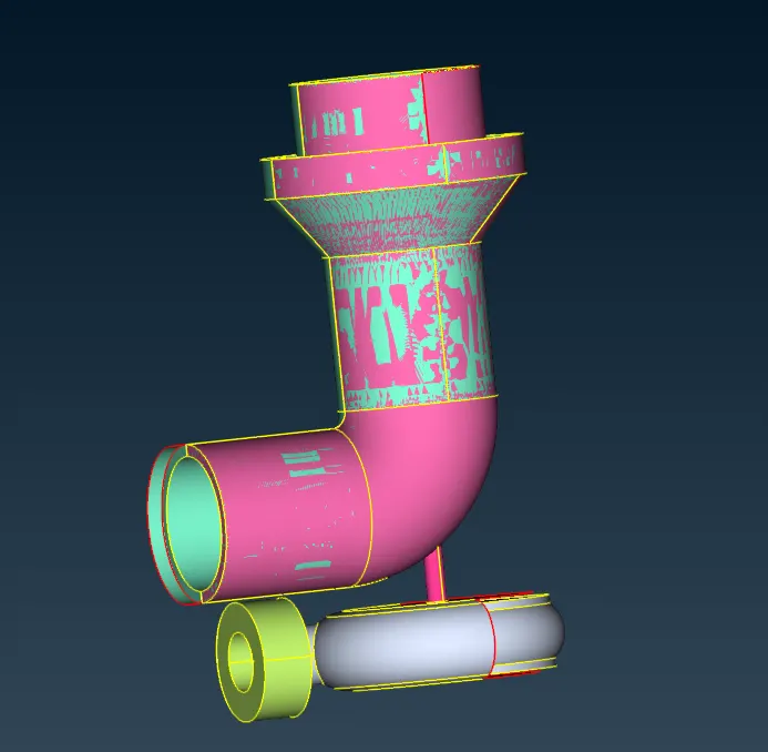
3 from PID option show only 11 no PID And Delete force fully by using compress option.
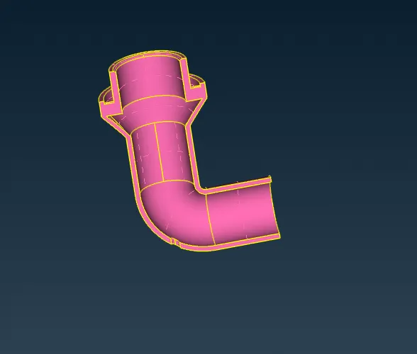
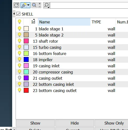
4.rename PID which helps to identify different parts from model.
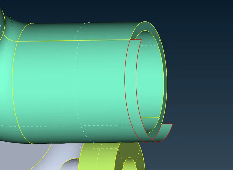
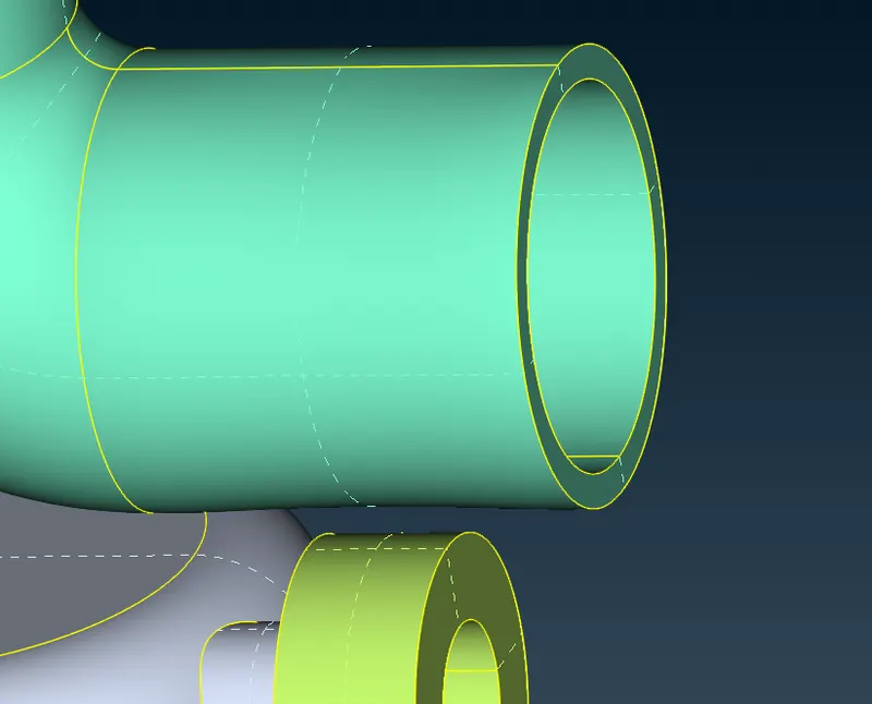
5.now we have to clean one by one PID region. show only compressor casing and see what has been done at this PID region.we have to delete some extended surface .as shown in below snap .
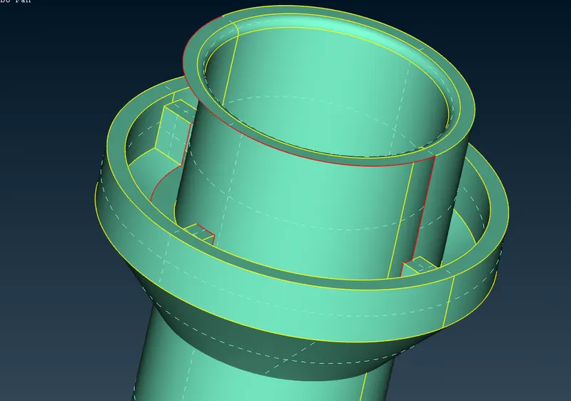
6.after this region. we need to patch this surface for that we are going to use multi project option in order to create hot point on top cone . by this we create small surfaces .and patch done successfully.
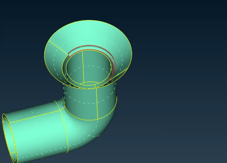
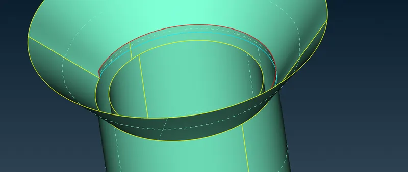
7. by using Intersect option we can delete unwanted merge surface .and surface look like.
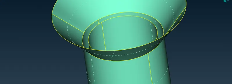
8.going at turbo casing also this region we can't able to patch surface in single attempt .we have to create some hot point for that purpose use parametric option and create hot point . by activating ent mode select cones and new surface created.by goes on we convert single cones to double.
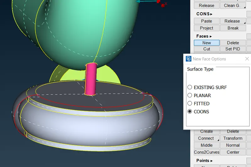
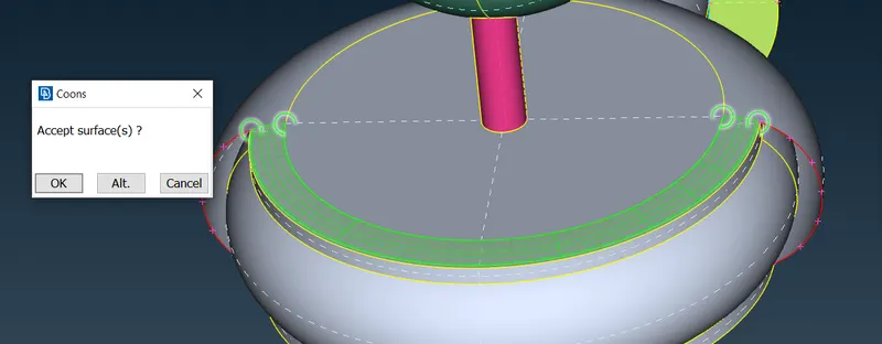
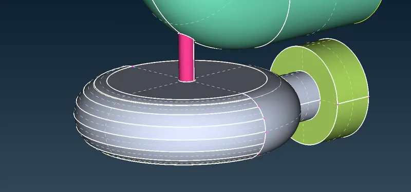
9.by execte geometry cleanup we notice there are many triple cone. avoid this triple cones if not needed.
10.now we need to delete overlapped surface from blade region. by deleting those surface we get closed volume which is required for mesh
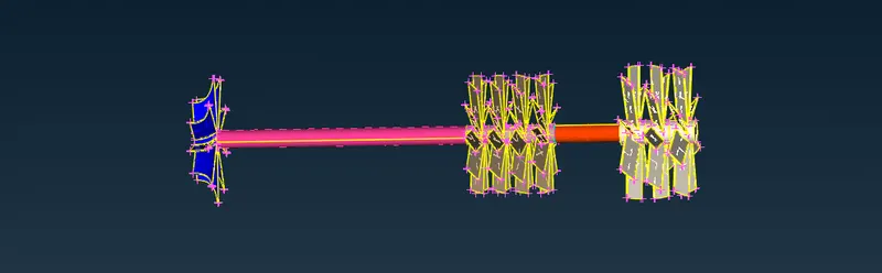
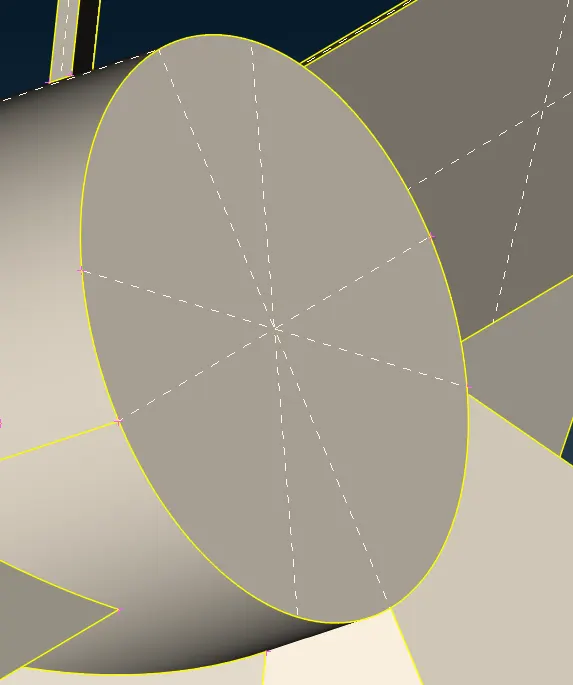
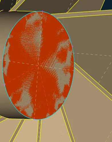
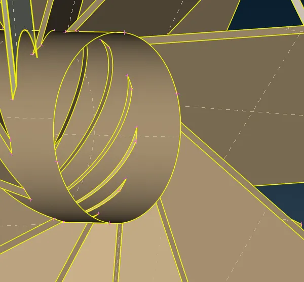
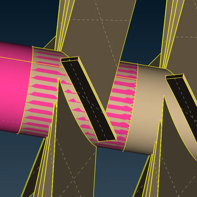
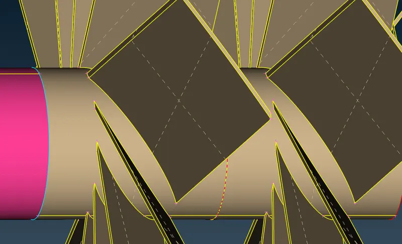
11.jump on the lower blade region. we need to apply cut over there in order to create or delete surface.
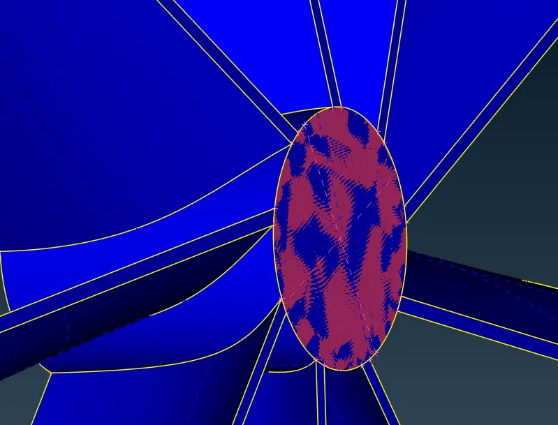
11.make sure you delete all overlapped surface .
12.we need closed volume for volumetric mesh .for that patch inlet outlet of casing .
13. now go to surface mesh assign mesh parameter and Quality criteria as given
- Blade stage-1 = 1 mm
- Blade stage-2 = 1 mm
- Impeller = 2 mm
- Shaft rotor = 1 mm
- Turbo casing = 5 mm
- Compressor casing = 5 mm
- Inlet casing cover = 5 mm
by spot mesh we got the mesh
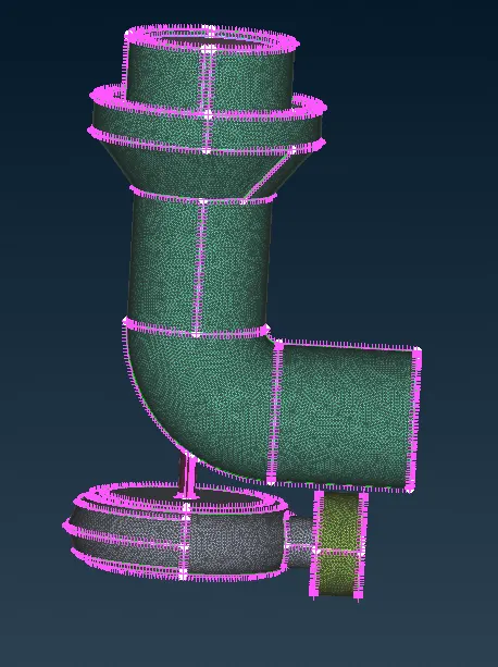
14.by adding few cuts at the mating region of mesh we got good mesh .and we saperate mesh region which is variying 1mm to 5mm. for that use paramatric cut .
16.go to volume mesh.click on define and choose whole db.we got 8 volumes. from which we required only inner volume. we have to delete that volume which not required or which are contain thickness.
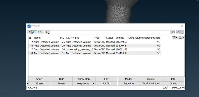
17.use tetra cfd and remesh the 4 volume in which fluid flows.
18.go at topo mode .we observe gliches this is nothing but volume .
18.by using not option we can observe the 3d elements.
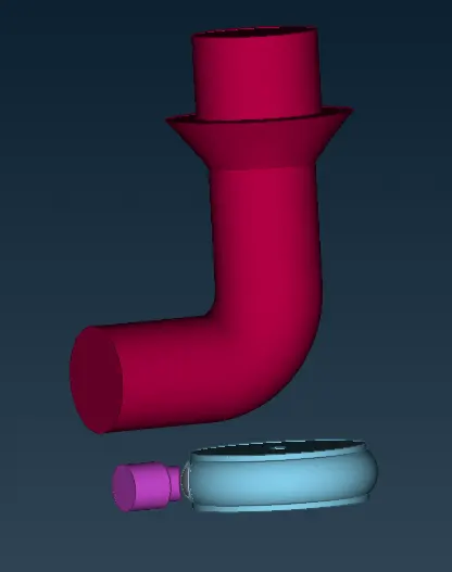
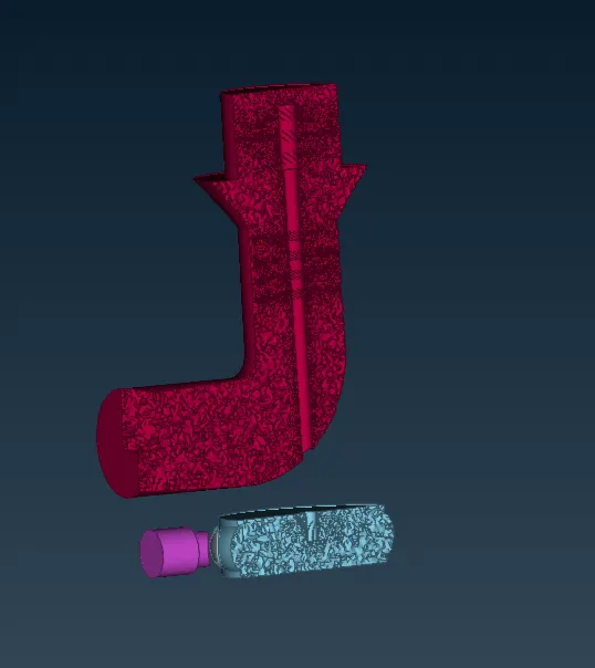
RESULT : from this we can oberve the volume mesh. what is at the blade region and where elements are smaller
what I learn from this challange.
1.import of model
2.patch the surface
3.assign PID for diffrent region
4.set mesh parameter
5.set quality criteria
6.deploy mesh
7.various isolating options
8.hidde options
9.topo clean-up
10.surfacemesh
11.intersect
12.volume mesh