Week 3 Challenge : CFD meshing on Turbocharger
AIM: Volumetric Meshing for the required Volumes of a Model of Turbocharger using Ansa.
OBJECTIVE:
Perform surface mesh with the given target lengths as per PIDs.
- Blade stage-1 = 1 mm
- Blade stage-2 = 1 mm
- Impeller = 2 mm
- Shaft rotor = 1 mm
- Turbo casing = 5 mm
- Compressor casing = 5 mm
- Inlet casing cover = 5 mm
THEORY:
Turbocharger:
A turbocharger (technically a turbosupercharger), colloquially known as turbo, is a turbine-driven, forced induction device that increases an internal combustion engine's power output by forcing extra compressed air into the combustion chamber. This improvement over a naturally aspirated engine's power output is because the compressor can force more air—and proportionately more fuel—into the combustion chamber than atmospheric pressure (and for that matter, ram air intakes) alone.
Manufacturers commonly use turbochargers in trucks, cars, trains, aircraft, and construction-equipment engines. They are most often used with Otto cycle and diesel cycle internal combustion engines.
Turbocharger construction and flow of gases
A turbocharger consists of a compressor wheel and exhaust gas turbine wheel coupled together by a solid shaft and that is used to boost the intake air pressure of an internal combustion engine. The exhaust gas turbine extracts energy from the exhaust gas and uses it to drive the compressor and overcome friction. In most automotive-type applications, both the compressor and turbine wheel are of the radial flow type. Some applications, such as medium- and low- speed diesel engines, can use an axial flow turbine wheel instead of a radial flow turbine. The flow of gases through a typical turbocharger with radial flow compressor and turbine wheels
Volumetric Meshing using ANSA:-
METHODOLOGY:-
- Topology Clean up
- Surface Meshing
- Volumetric Meshing
- Topology clean up:-
first we have to import Geometry
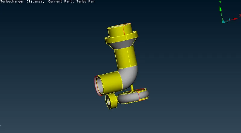
After that we have ot check the Single, double and triple cons. First we have to Delete the overlap surefaces. click on the cross section of the Overlaped surface and then Delete that surface.
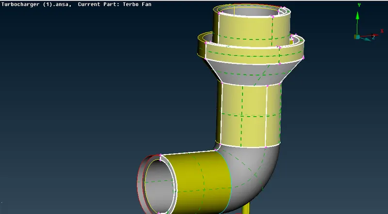
After Deleting the overlaped surface we have also deleted the extended surface and then Fill this by new surface. go to face> new> coons> select the cons and then click ok.
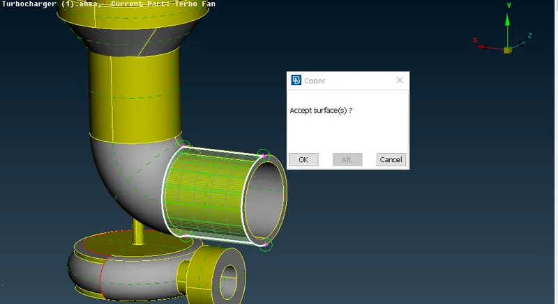
for the Bottom part we will create surface by the Projected Hot-points because when we generate the surface for the bottom part we don't get it the desired shape So, for the desired shape of the bottom part we generate the surface by adding the hot-points. Go to parameter > give the distance as 0.5> Click on the edge of the cons and add the hot-points at the edge of the cons and then Add the Hot-points and Generate the surface shown as the Image below:
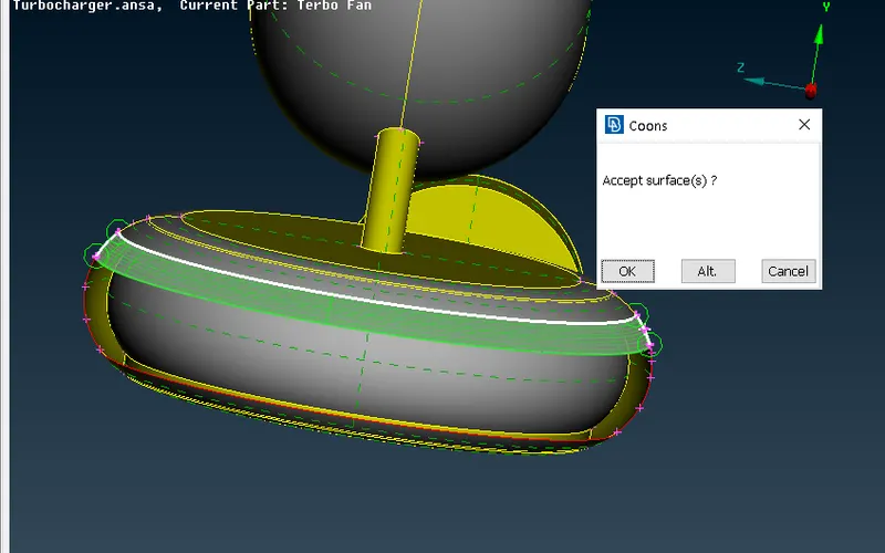
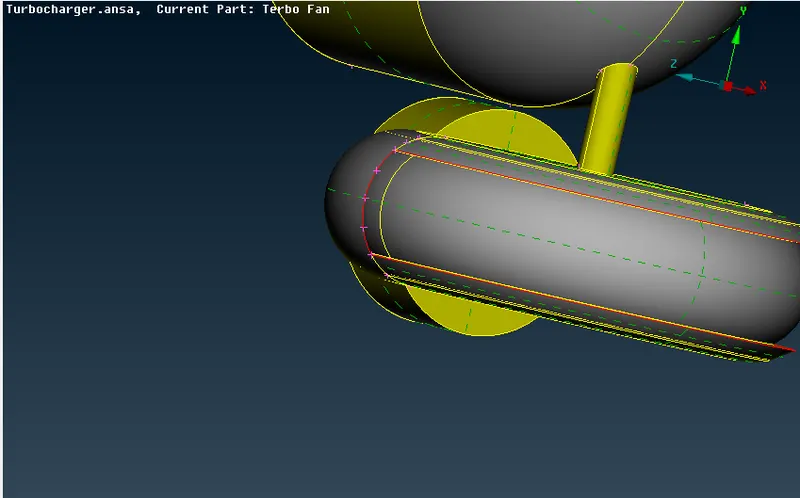
Like these Add the hot-point and Generate the Bottom Surface. Hence, we have Generated Surface Image shown in below:
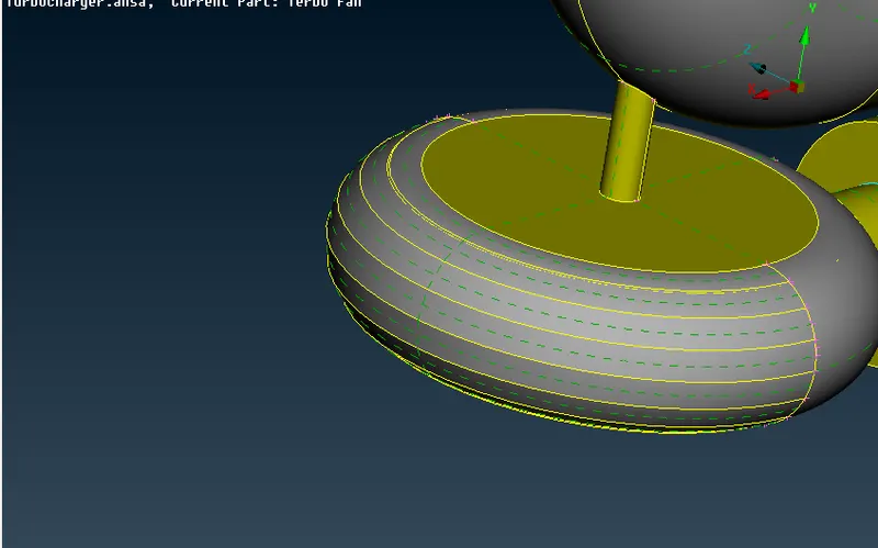
After that we will create surface here at the single cons but here are also overlap surface (i.e, here are triple cons) To delete triple cons First we hide the unwanted surfaces and then delete the overlap surfaces as shown in the Images below:
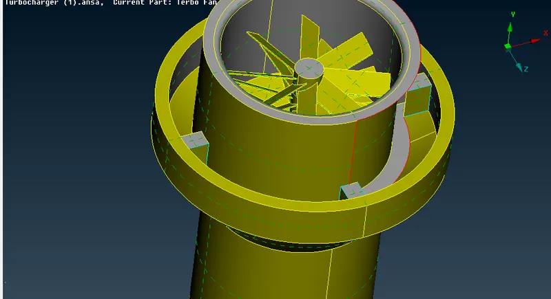
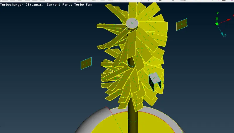
After deleting the overlap or triple surfaces we will generate the surfaces as the single cons to overcome this error.
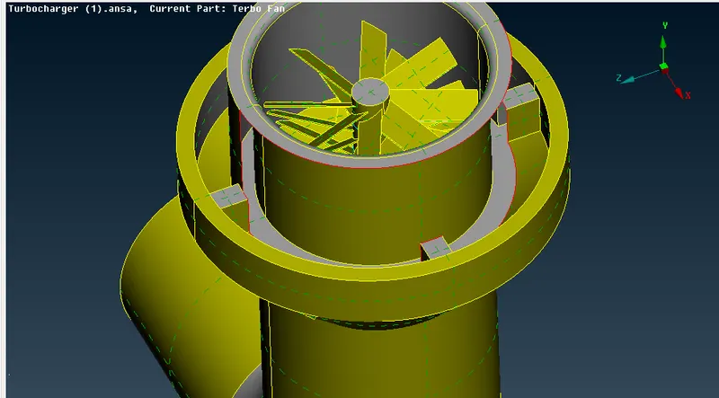
When we try to generate the surface by coons method the surface is generated wrong So, to generate the desired shape of surface First we will projected the hot-points at the parallel cons as shown in the Image below:
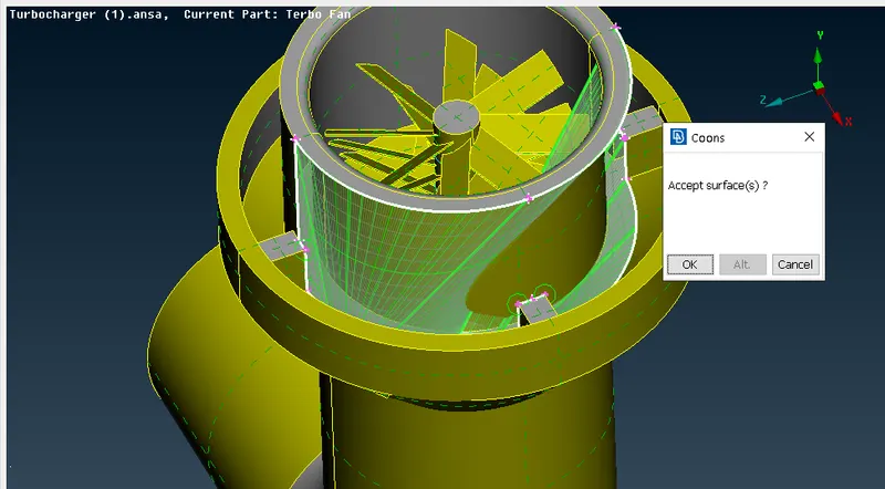
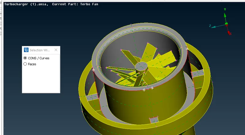
After that Go to faces> new>Coons> select the cons as per the hot-points as shown in the Image below:
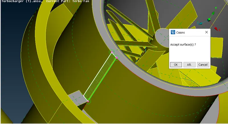
Like this Generate the all surfaces after this we left only the Rectangular single cons we have filled this surface by hole/ coons method.
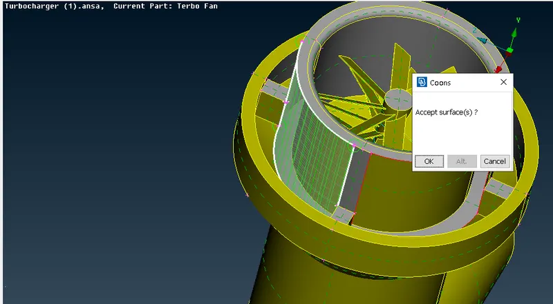
Here, is our final surface
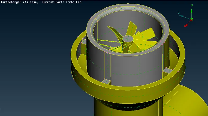
After that again we have chcked for the Single cons we got in this area To overcome this error Isolated all the unwanted surfaces and check. We got the intersect the surfaces In order to delete these surfaces Go to Faces> Intersect> Select the first face> Middle click for confirmation> select the 2nd face> Click ok
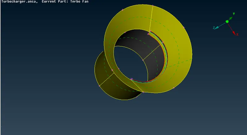
Pink face represents the first Intersecting face and Blue face represents the second Intersecting face.
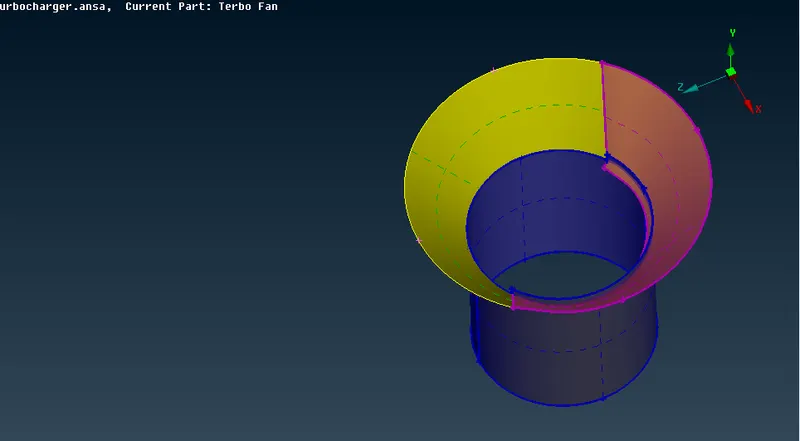
After that we got the Intersecting surface and then we will delete the Intersecting surface.
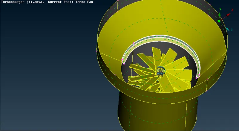
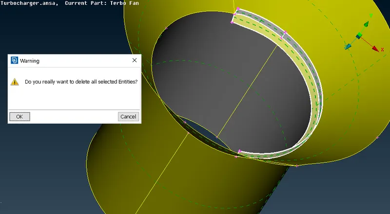
Here, is our geometry after deleting the Intersecting surface.
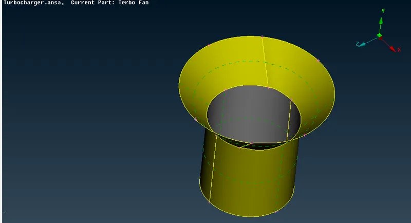
After that we again checked for Intersecting surface. Our single cons errors are now, Resolved.
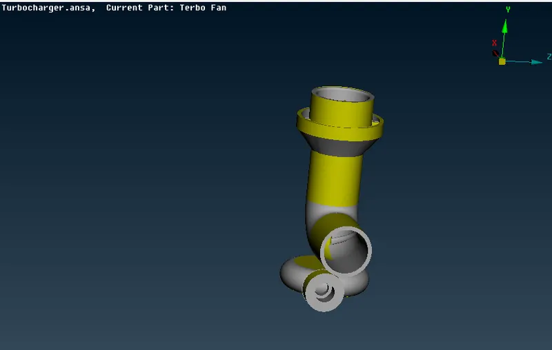
Then we checked for triple cons The bottom part triple cons are necessary and the then we checked our triple cons at upper part.
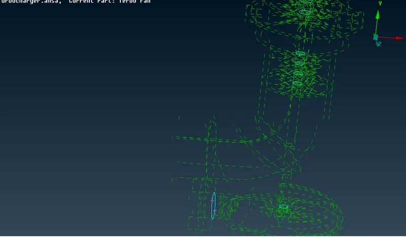
Isolate the rest of the parts and check the overlaped surfaces and delete them one by one.
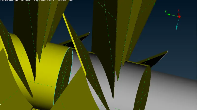
To delete the overlaped surface at the Impeller first we cut the surfaces from the blades through hot -points and then cut the required overlaped surface.
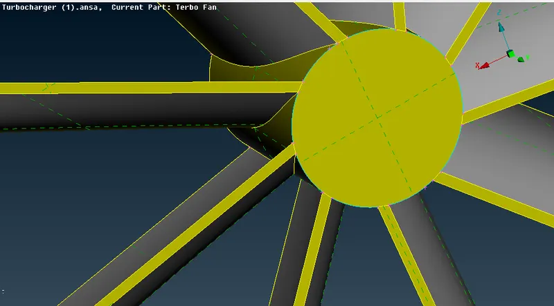
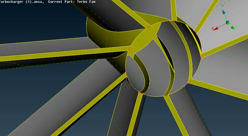
After that we find the triple cons here, the rotor shaft and at the Impeller For this First we have to project the area throuch at which the entire length goes upto and after that delete that surface and triple cons is not formed.
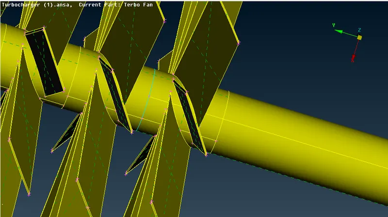
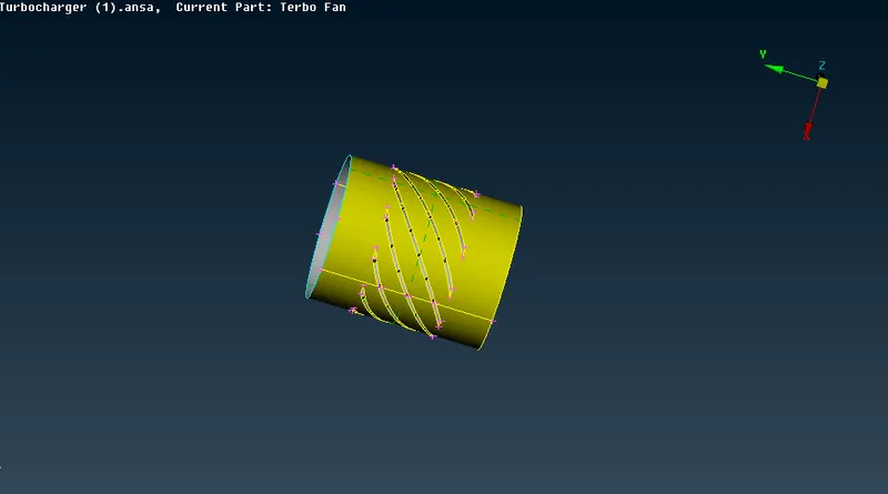
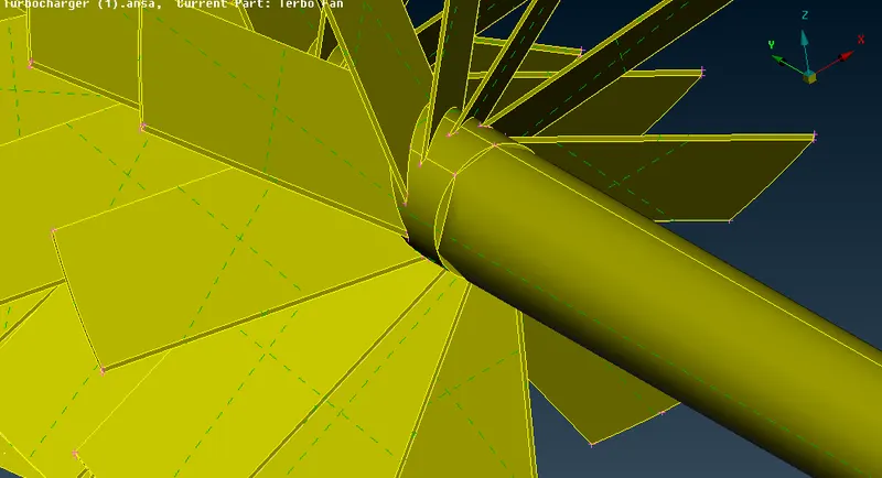
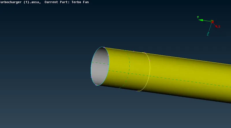
Delete this length upto projected part and then double cons is formed here, that is necessary.
- Surface Meshing:-
For the Surface Meshing First we have to Define the PID's
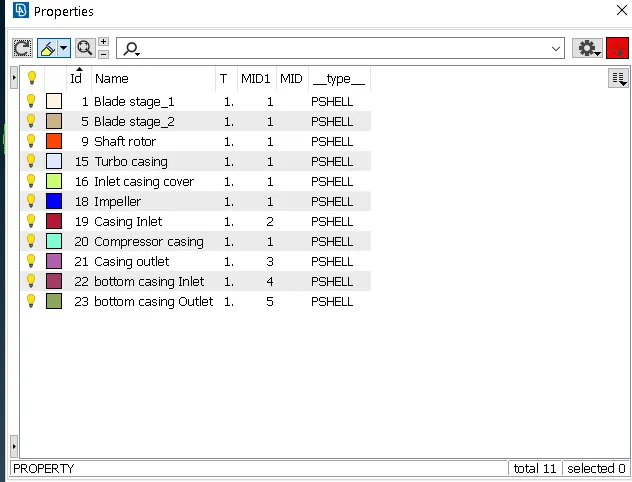
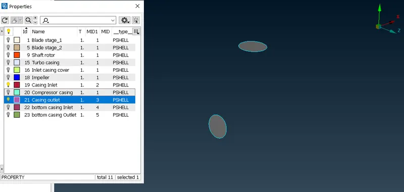
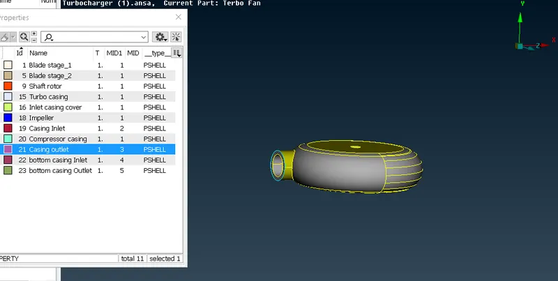
And after creating PID's we have to assigned thema according to the Geometry as shown below:-
Compressor Casing
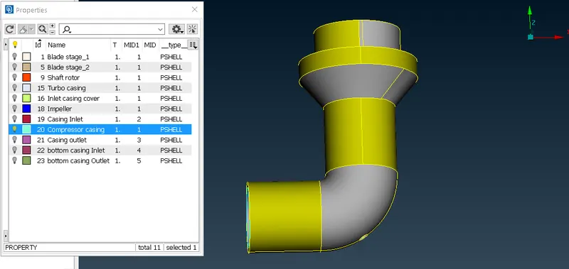
Casing Inlet and Outlet
TurboCasing
Bottom casing Inlet and Outlet
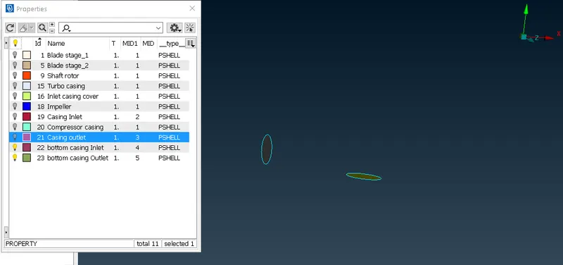
Inlet casing cover
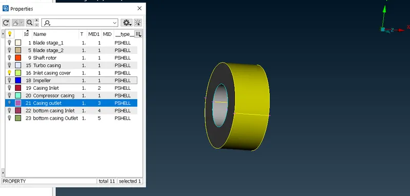
Inner body PID's we have created
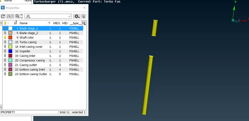
Rotor shaft
Impeller
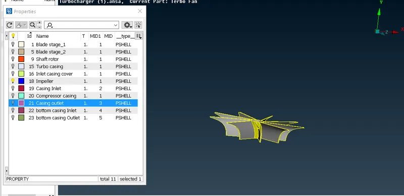
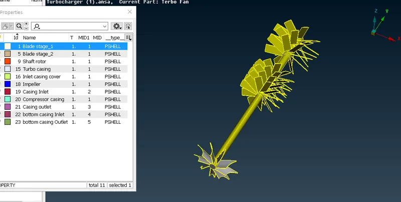
Blade stage1 and Blade stage2
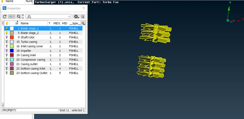
After creating PID's now our Geometry is ready for Meshing. In the Meshing first we created the Mesh Length by 4 parameters:
- Perimeter> Length> first we select the First Parameter> then select the whole body> middle click for confirmation> Input the Mesh length> then press Ok.
- Macros same as the Perimeter.
- Mesh quality criteria. Setting the minimum and maximum Mesh length.
- Mesh parameters set up. Target length, Minimum and maximum Mesh length set up. Element set up is also we done as Triangular Mesh Elements.
For this Study we Perform surface mesh with the given target Mesh lengths as per PIDs.
- Blade stage-1 = 1 mm
- Blade stage-2 = 1 mm
- Impeller = 2 mm
- Shaft rotor = 1 mm
- Turbo casing = 5 mm
- Compressor casing = 5 mm
- Inlet casing cover = 5 mm
Here, is the Meshed Geometry as shown below in the Images
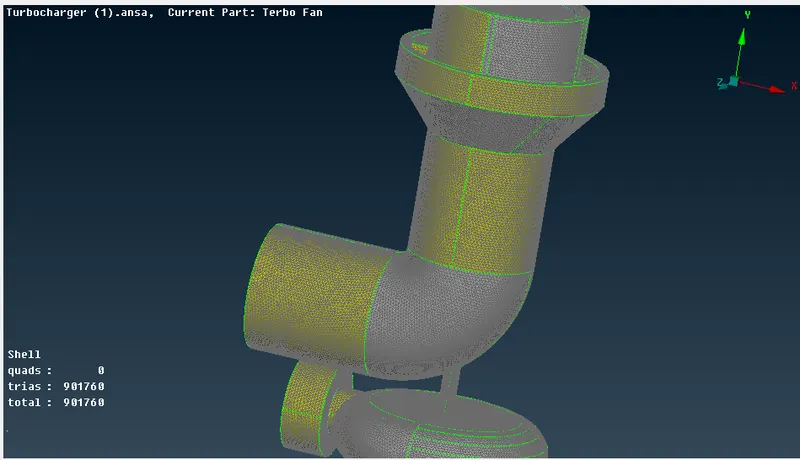
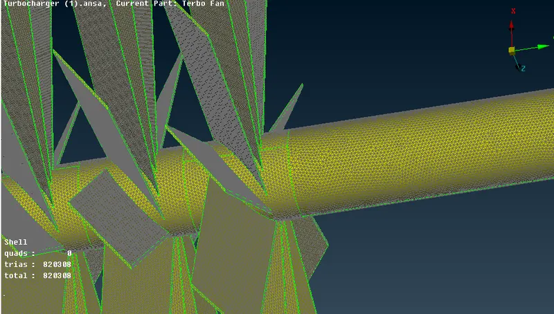
After that we Perform Volumetric Meshing:
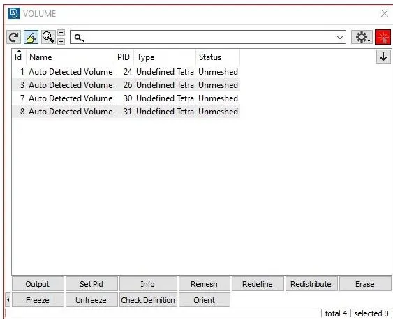
- Volume module> Define. In that defining the which model effect the Volume of the fluid.
- After defining the Required Volume we do Delete the unwanted Volume.
Here, is our Meshed Model:
https://drive.google.com/file/d/1hf7YgbNWMcluGN_LyHibU2A6Hyi_cSSl/view?usp=sharing
Conclusion:
- Geometry Clean up is carried out by removing the all the errors, interfacing components and overlaping components.
- Volumetric Mesh is done by uisng tetrahedral Mesh and using the above picture.