Week 3 Challenge : CFD meshing on Turbocharger
AIM:
To clear all the Geometrical and Intersection in the provided geometry & have to assign the PID with respect to the components in the assembly. And to mesh the component in the PID with the respective mesh length provided. And to perform the volumetric mesh for the geometry.
NEW TOOLS LEARNED:
- Hot Points ------> Insert (To insert the hot points in the preffered location)
- Hot Points ------> Project (To project the hot points to the chosen CONS)
- Curve ------->Transform (To project a new curve similar to the existing CONS as selected with respect to nodes)
- Transform -------> Copy -------> Symmetry (To make a symmetry of the existing entity or nodes)
- CONS --------> Project (To project a existing CONS on a face selected)
- Macros -------> Freeze/Unfreeze (To freeze/unfreeze the macros selected in the part. By freezing it, it will not chage with respect to the other part)
PROCEDURE:
1. Geometry Checkup:
After the geometry get loaded up, we have to check the errors in the component using Geometry Checkup Option.
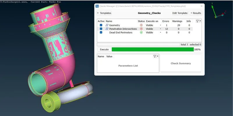
In the geometry provided, we are having 1 Errors and 29 Warnings in Geometry & 12 Errors in Intersections. We have to clear all these errors and warnings in order to go for the meshing.
2.Error rectification:
- Initially it is suggested to do the Faces------->Topo to merge the faces if it is not connected properly. By doing the topo we can merge the faces in a proper manner.
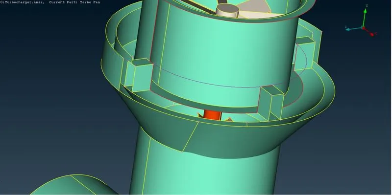
- CURVE CREATION: In the provided geometry one face is missing. So in order to create the face in ease manner, we are going to use Transform -------> Curve Option by which we can project the desirable CONS with respect the node points(Hot points) selected. The purple line shows in the image is the curve created using transform option. Then with respect to the curve we can create faces using Faces -------> New option. Here the faces is created using CONS. After creation of the new faces, we can delete the curve that is not in need anymore.
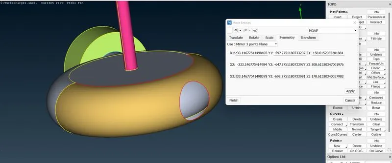
- Symmetry Entity Creation : In the turbine casing provided, half of the outer part is missing. By the normal way of creating faces it is not possible to create the missing faces. So here we are using the symmetry option to create the replica of the already existing entity in the geometry. We have to be do it carefully after understanding the part is a symmetrical one with respect to the axis point. We have to choose Transform -------> Copy -------> Symmetry option. In these option there comes various option of creating the entity with respect to what. So here we are choosing 3 point symmetry, whereas it will required 3 point to create the new entity. The image shows the creation of entity using symmetry option using 3 points.
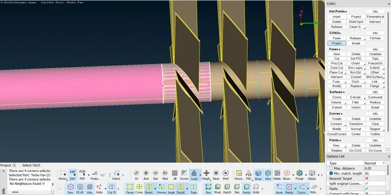
- CONS projection: In the geometry provided, we are having two parts intersected with each other. On that we dont want the particular space occupied by one part over the another. By here comes the trouble we cant able to delete that particular space because during delete the entire shaft will get selected for it. So we need to seperate that shaft into two to delete the desired space. For that CONS ------> Project will be used to seperate the part into two by creation of the CONS over the surface. After the CONS is created as shown in the figure we can easily delete that particular space using the Faces-------> Delete Option.
- In the shaft rotor, rotor blade1, rotor blade 2 and impeller, it is found that it is assembled as a seperate part. So for that ANSA will consider each part as a seperate volume. As viewing the geometry and understanding it requirements, the flow will only occur at the outer part of the components. So better we can make all these parts with a single volume. For that we have to delete all the faces on the each and every component assembled and make it as a single volume component.
- In the part where compressor casing and the rotor shaft assembled, it is found that it get intersected with each other. So we use the Faces -------> Delete option to remove the unwanted faces.
3. Closing of all open area for Volumetric Meshing:
After clearing all the errors and warnings we have to go for meshing. Before that we have to create new faces on all the open sides of the assembly. Because ANSA will only do volumetric analysis in a closed component internally. So for that we used the Faces-------->New------->Planar to close all the open faces of the component to ensure there must not be any open side on the way where we want to do volumetric analysis.
4. Setting of PID:
In the project it is given to mesh in a localized manner. That is each and every part assembled to the component have different Spacing Length. In order to do it effectively we have to set PID for each and every component with the name we can easily understand. So after doing that there are still certain unassigned PID that we dont want. For deleting the Unassigned PID we can use Compress option to delete the unassigned PIDs
5. Surface Meshing:
After doing the needs now we are good to go with the surface meshing. We have to choose the PID with respect to the Target Length and start doing the meshing operation by using Spacing -------> Auto CFD option. Here I upload all the images done while meshing.
Meshing of 1mm in Shaft Rotor, Rotor Blade 1 and Rotor Blade 2:
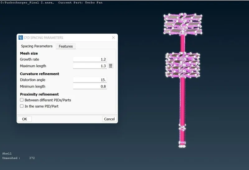
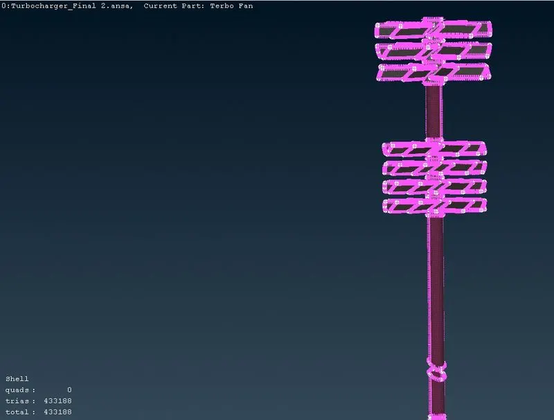
The mesh generated after this is 433188.
Meshing of 2mm in Impeller:
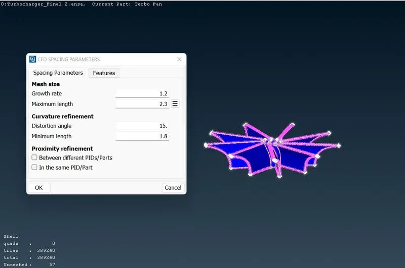
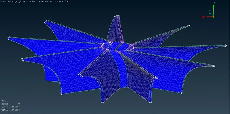
Meshing of 5mm in Compressor Casing, Turbine casing and Inlet casing cover:
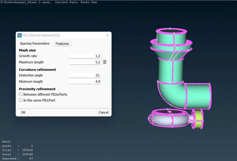
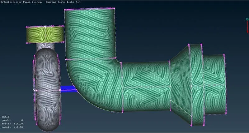
The total number of elements after meshing is 614100.
6. Volumetric Meshing:
After doing the surface meshing, then we can do the volumetric meshing. For that go to the Volumetric option. On that we have to define it. By doing that One dialog box will appear that shows the every volume the ANSA found in the part loaded. So we have to carefully choose the volume part depending upon the flow requirements particularly needed for the project. After choosing that, in the same dialog box itself in the mesh type we have to give the required mesh type. We have to choose depending upon the requirement of the mesh type. Here we chose Tetra CFD option and then we have to mesh it.
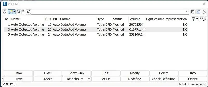
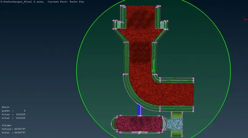
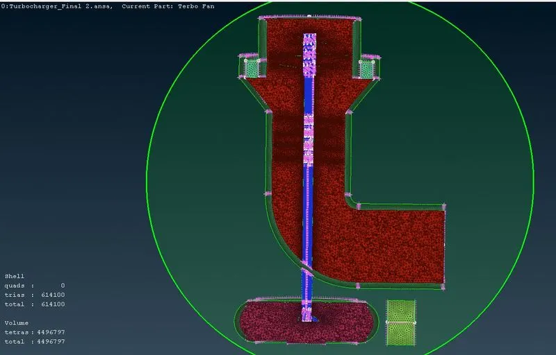
The total number of elements present in the volume is 44,96,797.
Here I also include the images of the volume of the volumetric meshing alone.
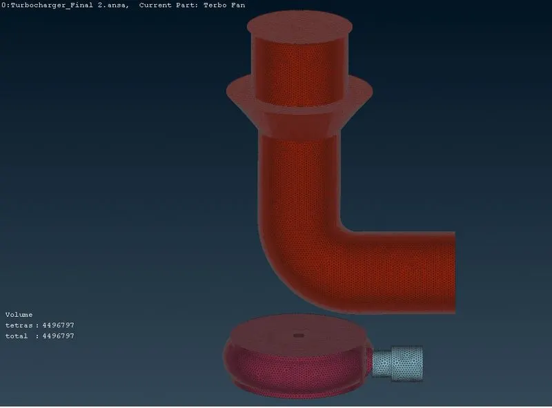
https://drive.google.com/drive/folders/1YqDd69aJ0ADWkO6h1SDtpVpsRbZVracO?usp=share_link
Result:
Thus by that with the given geometry we found the errors in the geometry. And we cleared the errors. And then we assigned PID for each component to allocate the different target length for surface meshing. And the volumetric meshing is done.