Week 3 Challenge : CFD meshing on Turbocharger
Aim: To perform surface meshing followed by volumetric meshing on a turbocharger, with target lengths as mentioned in the problem.
Working: Turbocharger is a device which is used to increase the pressure of air in IC engine. It uses the exhaust gas to run the turbine blade which is connected to the compressor blade. So as turbine blade rotates, compressor blade also turns, cause air to pass through it increases the pressure, and high pressure air go to the inlet system of engine.
Procedure: First we will check for units and resolution. Units is in mm and resolution is also good quality. Then we will check for the geometry checks. We will get 1 geometry error and 29 warnings ( 2 triple cons and 27 single cons); 12 intersection errors. We will remove all the errors; and then finally we will get 2 triple cons which is unavoidable. Then we will give the PIDs for all the parts, i.e; Turbine casing, compressor casing, turbine inlet, first stage blade, second stage blade and impeller. Then we will do the surface meshing. For that we will give the target lengths accordingly given in the challenge and generate mesh. We will get 4,65,828 number of triangular elements. Then volumetric mesh is done, using volumetric mesh option, and we will delete all the external surface and we will remain with the 3 internal fluid domain. Then tetrahedral CFD mesh is generated for all the three domains. Thus we will generate volumetric mesh. We will get 3789263 number of tetrahedral elements.
Preprocessor settings:
The intial geometry is given below.
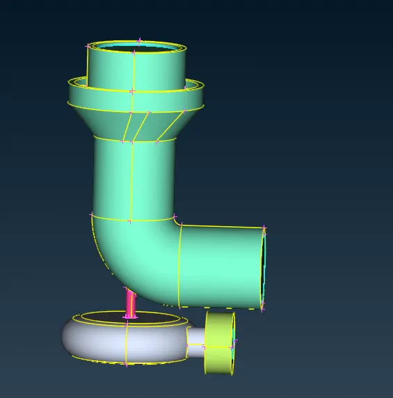
Starting we have 1 geometric error and 29 warnings; and 12 intersection errors. After the cleanup we will have just 2 warnings only (triple cons which are unavoidable as it is intersection of 3 faces)
Then we will assign PIDs to the domains.
Solid domains
(a) Turbine casing
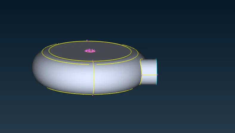
(b) inlet cover casing
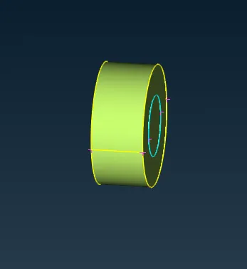
(c) Compressor casing
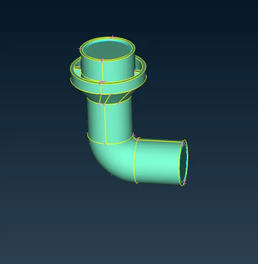
(d) impeller
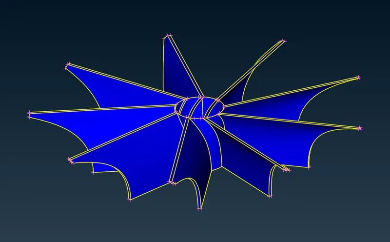
(e) Blade stage 1
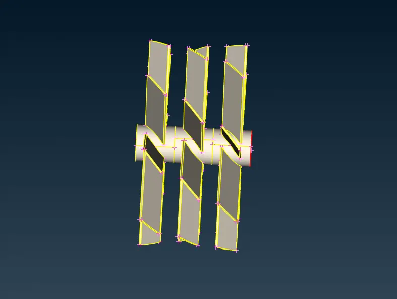
(f) Blade stage 2
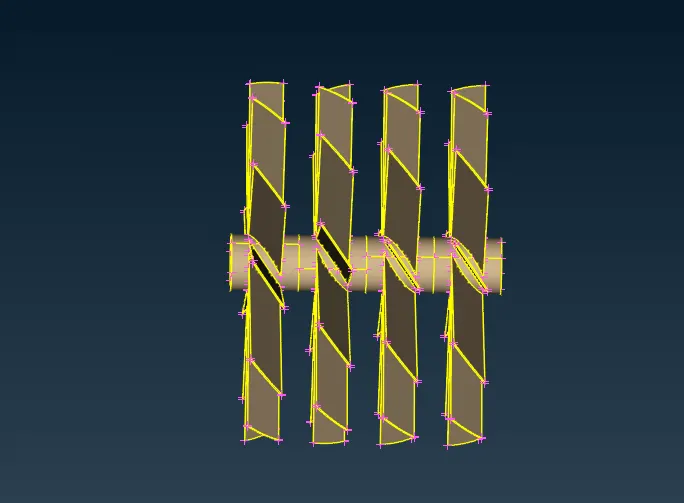
All the PIDs are given below
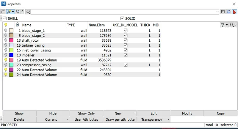
Now the surface meshing is done using Spacing and AutoCFD and will give perimeters with minimum and maximum target length, then with macros with minimum and maximum target length and then perform meshing using CFD mesh algorithm.
(i) Target length of 1 mm.
Components: Blade stage 1, Blade stage 2 and shaft rotor
Minimum Target length 0.3 mm
Maximum Target length 1.5 mm
(ii) Target length of 2mm.
Components: Impeller
Minimum Target length 1 mm
Maximum Target length 3 mm
(iii) Target length of 5 mm.
Components: Turbine casing, Inlet casing cover and compressor casing
Minimum Target length 1 mm
Maximum Target length 3 mm
Results:
(a) Surface mesh
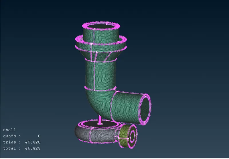
This is the surface mesh generated. The total number of triangular mesh is 465828. Make sure to use Freeze option while meshing.
Now we will perform the volumetric mesh.
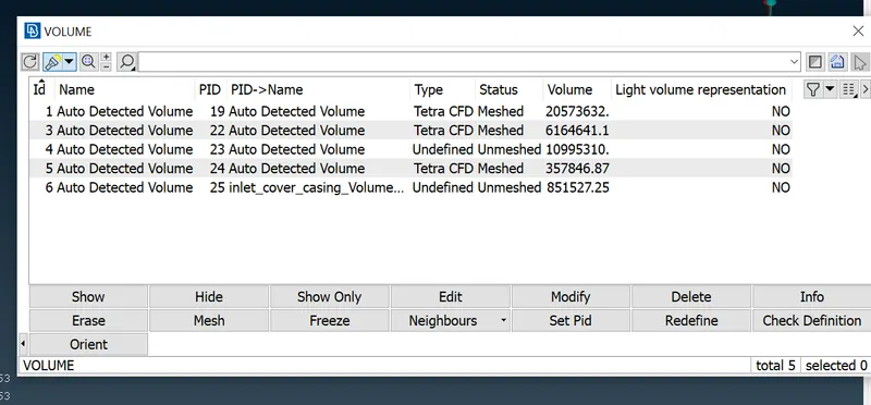
Here will do fluid domain creation of internal surface. We will give Tetra cfd mesh and create mesh. Other domains we will delete.
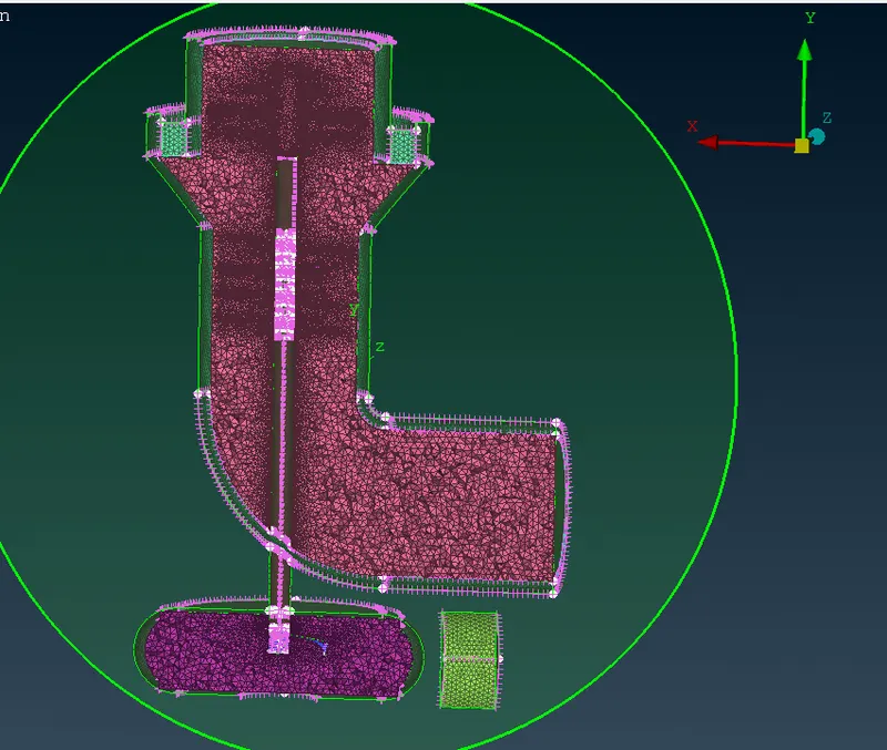
This is the volumetric mesh we obtained and it is in XY plane view.
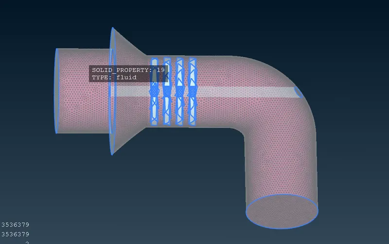
Fluid domain volumetric mesh
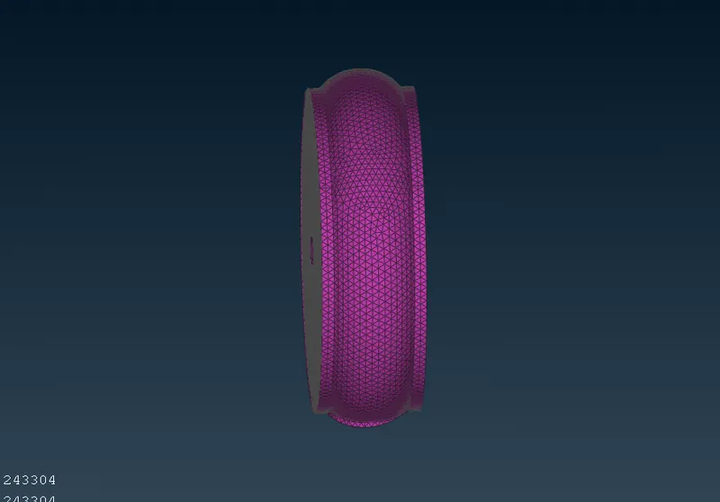
Fluid domain volumetric mesh
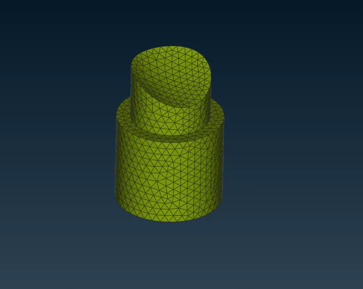
Fluid domain volumetric mesh
Conclusions:
We have obtained surface meshing and volumetric meshing of turbocharger. The surface mesh was done using the target lengths given in problem; while volumetric mesh was done by creating fluid domain inside ; and we have to ensure there is no open surface so have to close all the open surface. We have obtained total of 4,65,828 number of triangular elements (surface mesh) and 37,89,263 number of tetrahehdral elements (volumetric mesh)