Week 3 Challenge : CFD meshing on Turbocharger
Aim
To mesh different parts of a turbocharger with the above given target values.
Introduction
A turbocharger is a forced induction device that is powered by the flow of exhaust gases. It uses this energy to compress the intake gas,forcing more air into the engine in order to produce more power for a given displacement.
Like other forced induction devices, a compressor in the turbocharger pressurises the intake air before it enters the inlet manifold In the case of a turbocharger, the compressor is powered by the kinetic energy of the engine's exhaust gases, which is extracted by the turbocharger's turbine.
The main components of the turbocharger are:
- Turbine – usually a radial turbine design
- Compressor – usually a centrifugal compressor
- Center housing hub rotating assembly
Procedure
1.The file was copied into ANSA as it is.
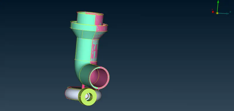
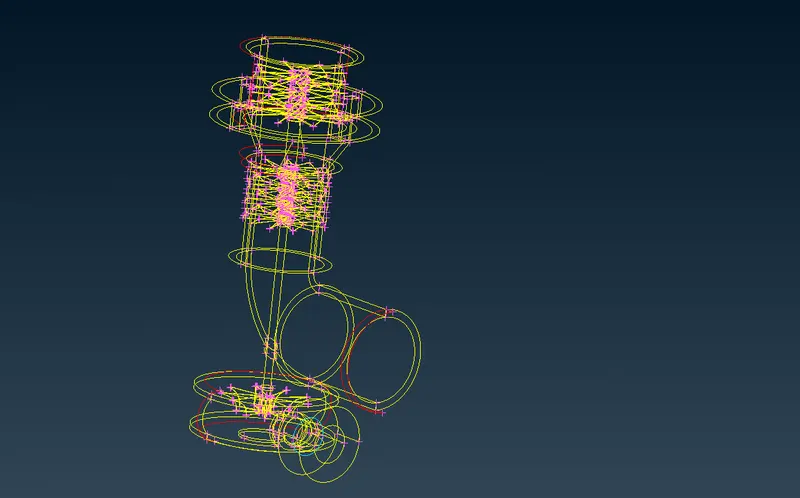
2. The errors of this geometry were rectified ,the PID's were assigned and the meshing was done.
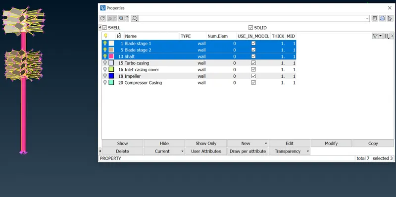
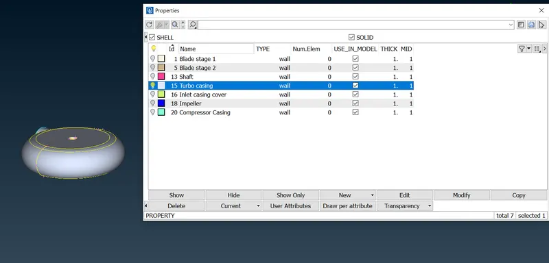
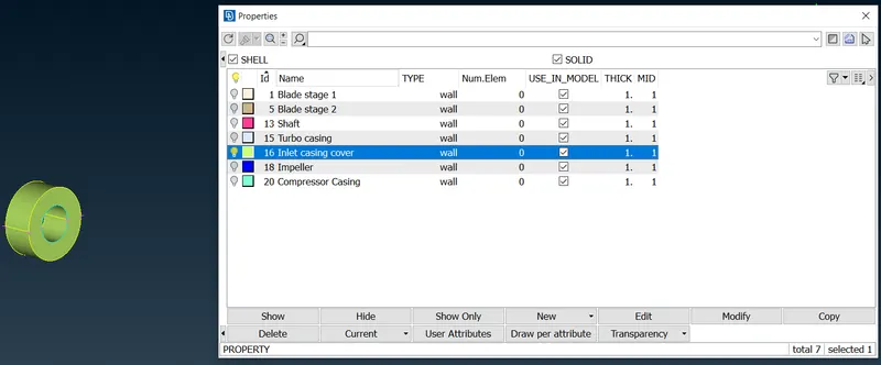
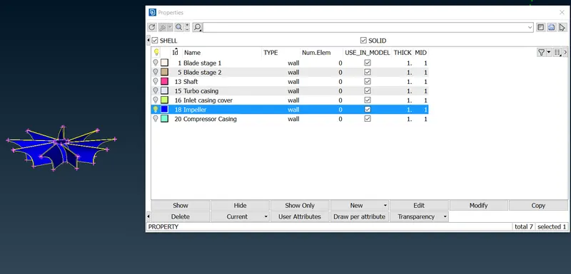
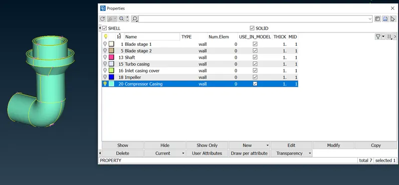
PID's are as shown below
Meshing
1.Surface meshing
Blade stage-1 = 1 mm
Blade stage-2 = 1 mm
Shaft rotor = 1 mm
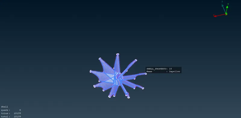
 Impeller = 2 mm
 Turbo casing = 5 mm
Compressor casing = 5 mm
Inlet casing cover = 5 mm
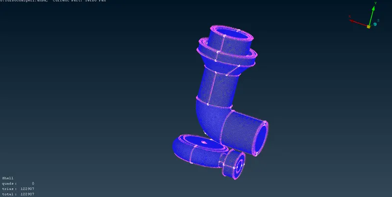
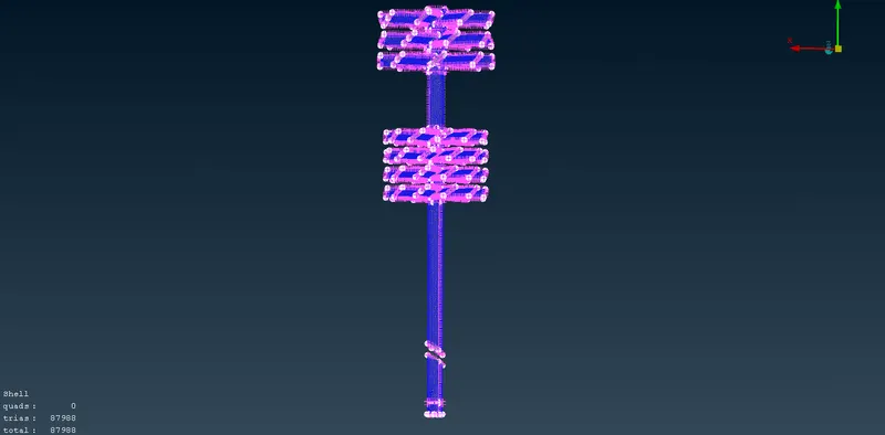
Final mesh
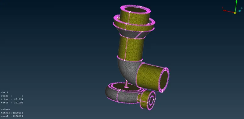
2.Volumetric mesh
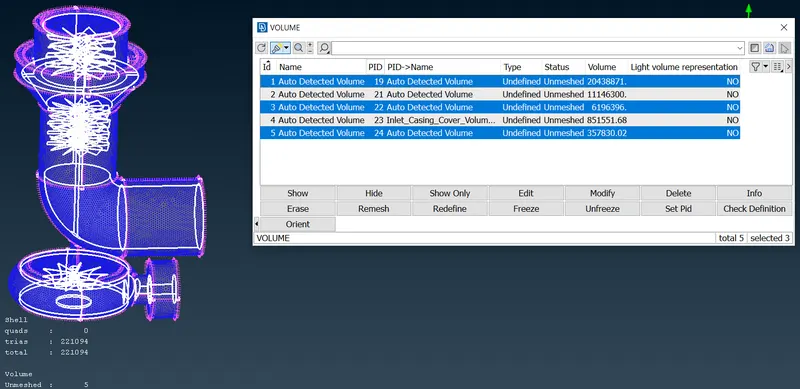
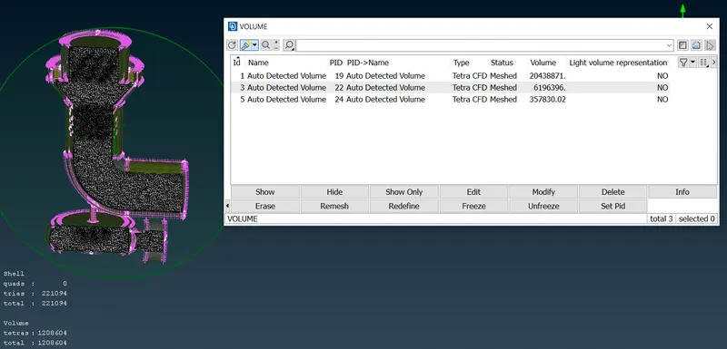
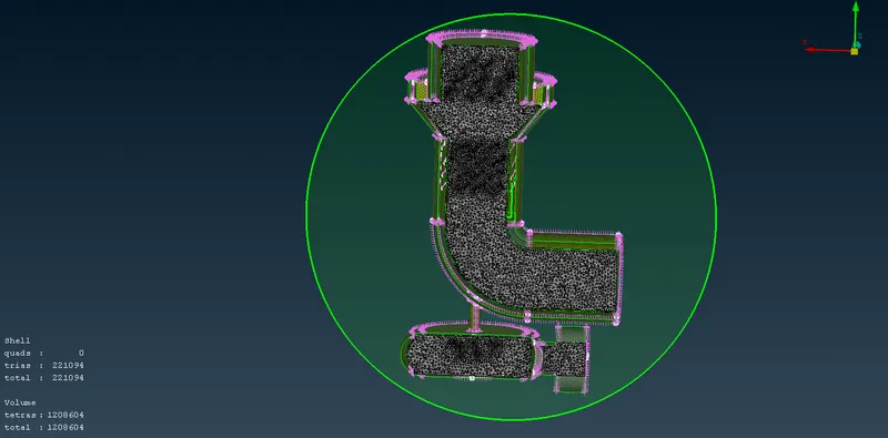
From the above picture only the highlighted parts were kept and the parts were removed as we required only the volumetric mesh i.e, only the inside part of the turbo charger was considered the outside portion was deleted.
Result
The given turbocharger model was corrected,named & meshed according to the target length valuesand the given mesh diagrams are shown above.