CFD meshing on Turbocharger
OBJECTIVE:
- To perform topological clean-up on the given CAD geometry of a turbocharger.
- To make proper surface & volumetric mesh for CFD simulations.
INTRODUCTION:
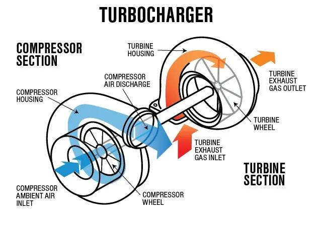
A turbocharger (often called a turbo) is a forced induction device that is powered by the flow of exhaust gases generated at the outlet of an internal combustion engine.
The flow energy of exhaust gases turns the rotor of the turbine blades which is also coupled to an air compressor.
The air compressor increases the density of inlet air supplied to the I.C. engine which increases its power output. The only drawback of a turbocharger is that at low engine speeds the exhaust gases do not provide adequate kinetic energy for the compressor to work and only increase the back pressure at the engine exhaust.
This is why a turbocharger is used mostly in high-powered engines. In low-powered engines, a turbocharger can be used by carefully selecting the engine configurations and budget constraints for engine parts.
PROCEDURE:
- Topological cleanup
- Imported image
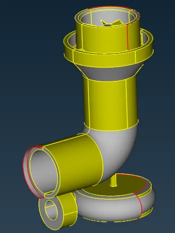
- Closing compressor casing
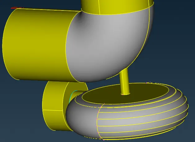
- Deleting extra surfaces (pink-colored regions)
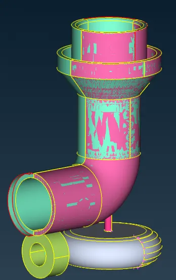
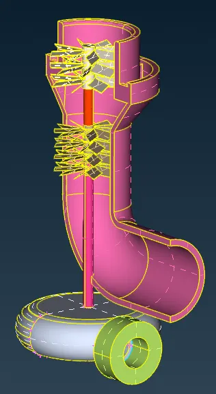
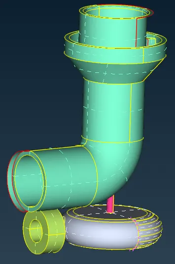
- Deleting extended surface. First, the old surface is deleted to remove the surface flange then, a new surface is created.
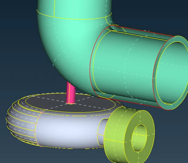
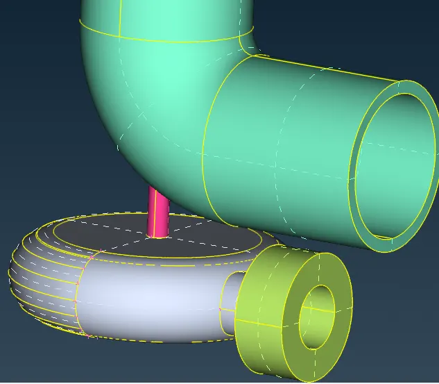
- Patching empty faces near the turbine outlet.
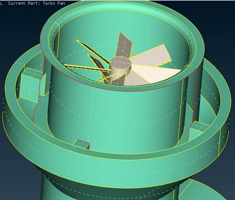
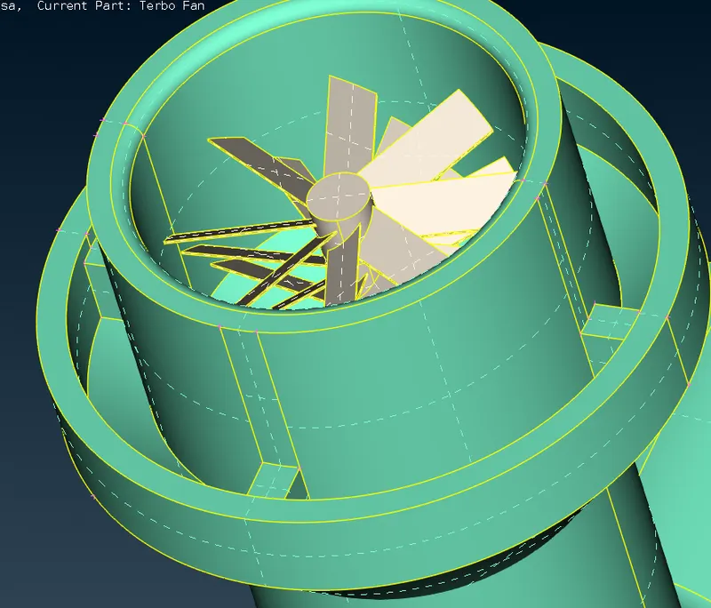
- Overlapping surfaces near turbine outlet. These surfaces extend into each other but no triple CONS are there so, we need to intersect the overlapping surfaces so as to delete them.
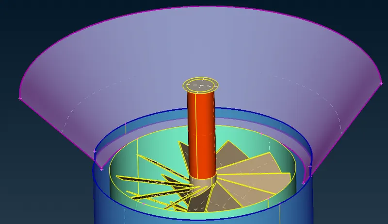
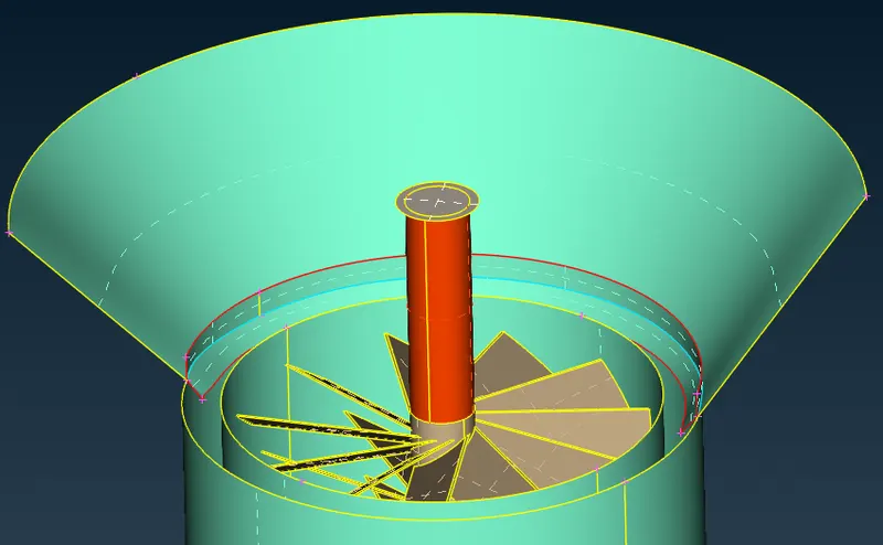
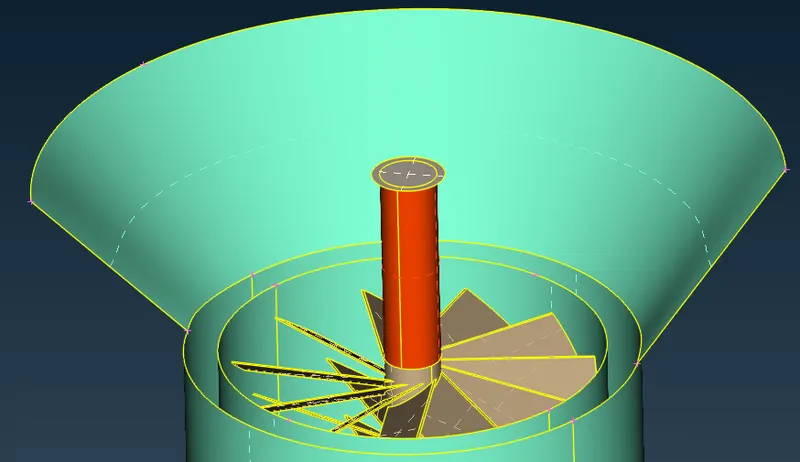
- Deleting extra surfaces on the turbine shaft.
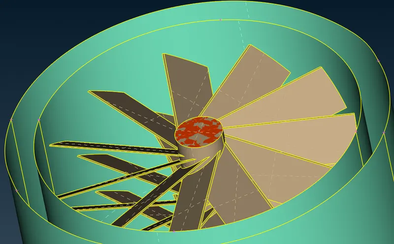
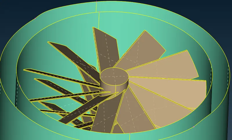
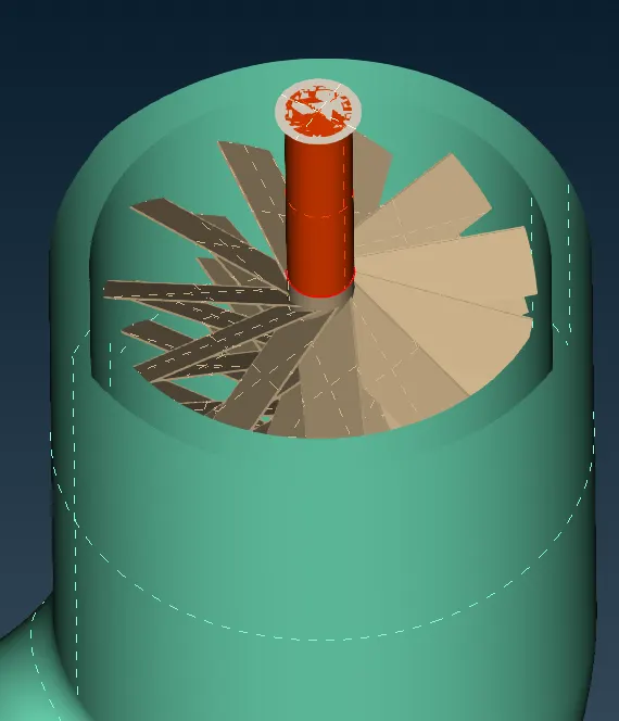
- Checking the geometry. The triple CONS on the compressor outlet are needed and hence are not a geometry error.
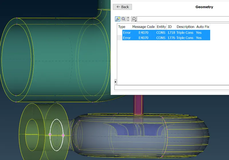
- Closing the geometry.
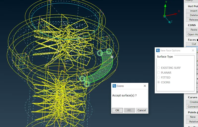
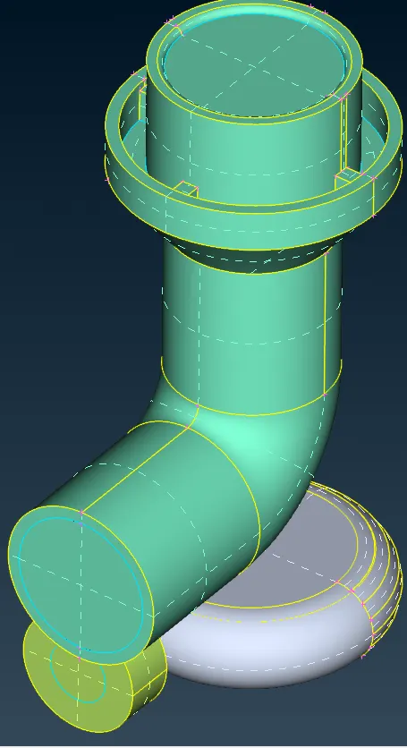
- Setting PIDs.
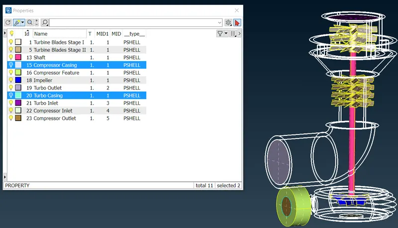
- Imported image
- Meshing
- After topological clean-up, the surface mesh is generated with the given specifications.
- Blade stage-1 = 1 mm
- Blade stage-2 = 1 mm
- Impeller = 2 mm
- Shaft rotor = 1 mm
- Turbo casing = 5 mm
- Compressor casing = 5 mm
- Inlet casing cover = 5 mm
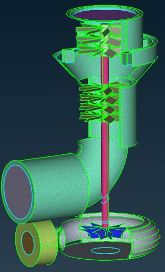
- For volumetric mesh, the volumes are auto-defined using ANSA and relevant volumes are retained.
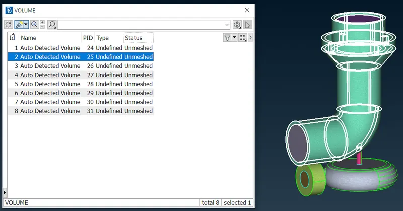
- For CFD, only volumes through which fluid flows are relevant. So, the volumes below are deleted.
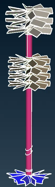
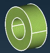
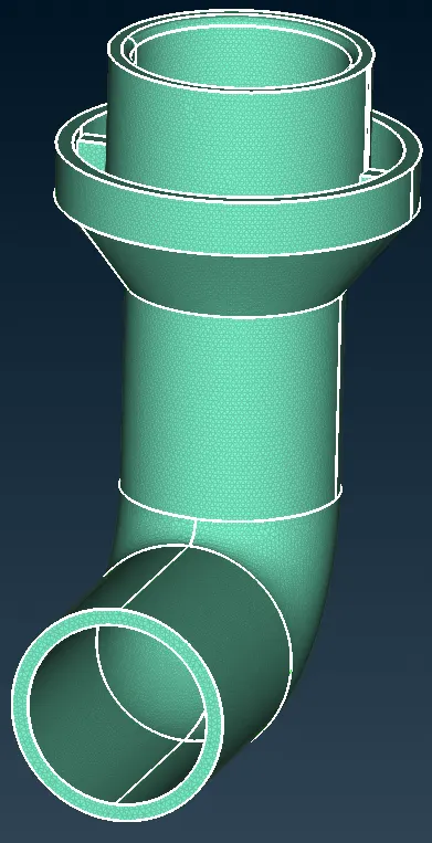
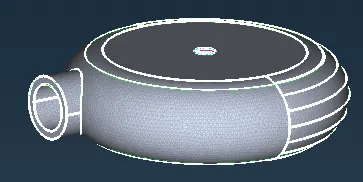
- The remaining regions are meshed.
- After topological clean-up, the surface mesh is generated with the given specifications.
- Conclusion
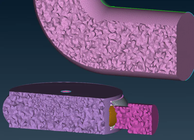
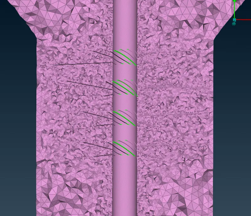
- Above meshes are finer near turbine and compressor blades.
- This is important for CFD appications so that flow variations are captured well near blades.