Week 3 Challenge : CFD meshing on Turbocharger
Aim: CFD meshing on Turbocharger
Procedure:
Initially, the 3D model is imported in the software.
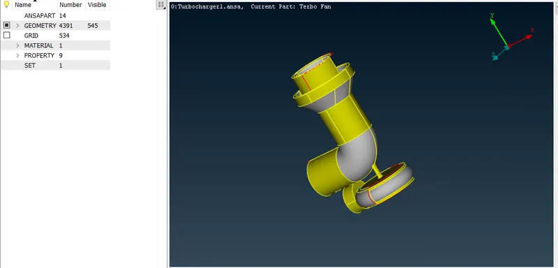
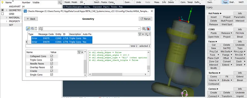
Single and triple cons are identified by usng geometry check.
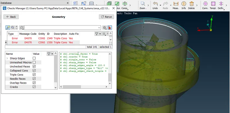
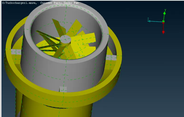
Empty spaces and single con are filled. The one case is shown below
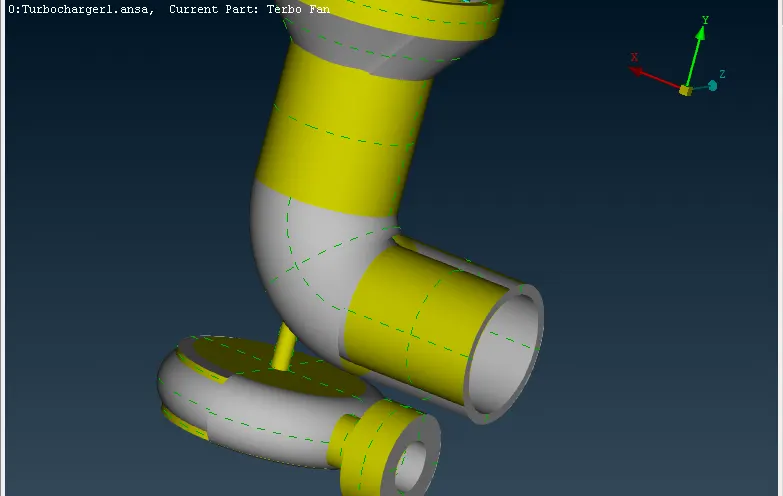
The remaining part is patched using the New Face option.
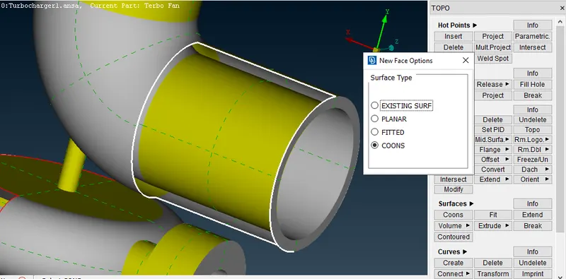
The similar procedure is done on the other single con.
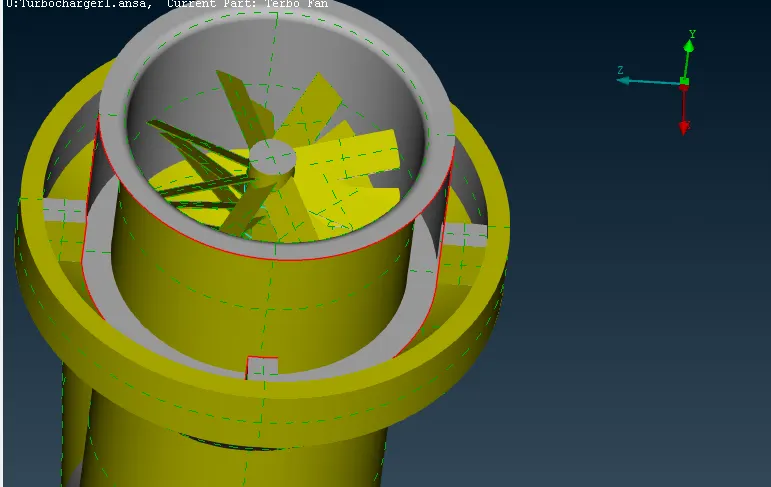
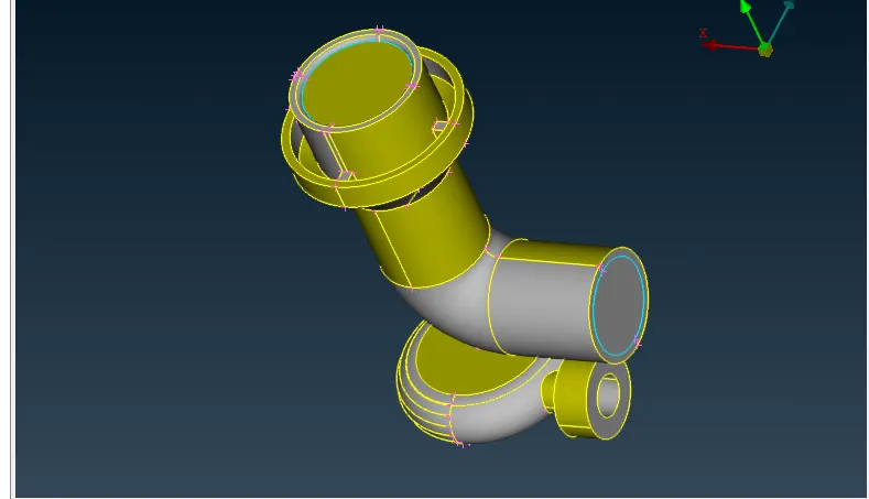
The Final surface after patching looks as below.
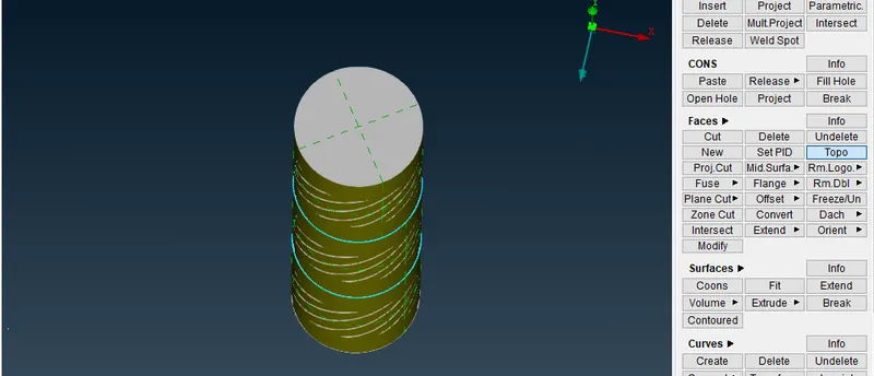
Triple con are found on the inner shaft. It is removed as follows:
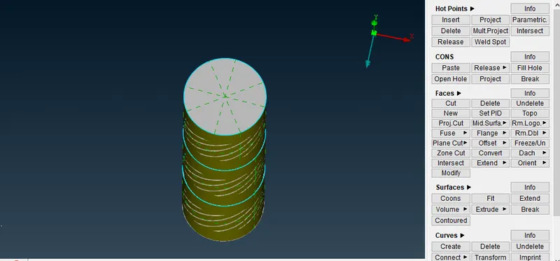
The surfaces in between the saft are deleted so as to loose the con.
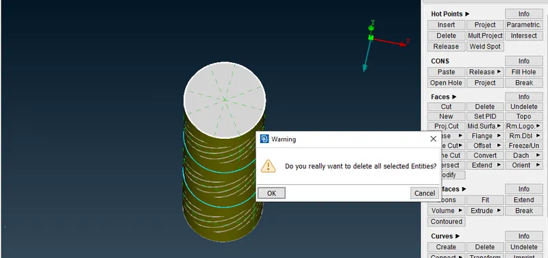
By using the release con on the deleted face, single ocn is obtained and further by using the TOPO command it is converted back to the double con.
The following image shows the tidious patch to be made. Any direct surface is difficult to be made here. so the side cons are divided in the number of cons.
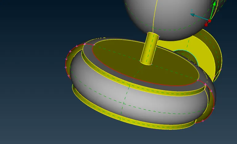
All th surface is made using different small patches.
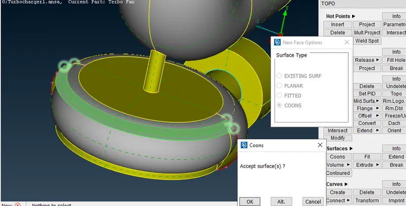
Finally, a full surface is obtained.
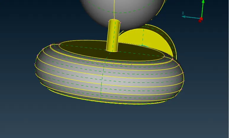
The whole geometry is out of errors, the only left triple can not be deleted as it not a problem and it is required to be there.
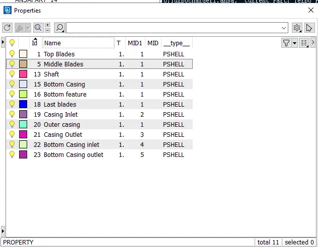
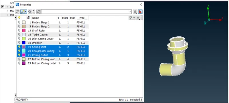
Each of the PID is gien some random naming initially.
Surface Mesh:
The surface mesh for each of the part is made and each is defined below.
- Blade stage-1 = 1 mm
- Blade stage-2 = 1 mm
- Impeller = 2 mm
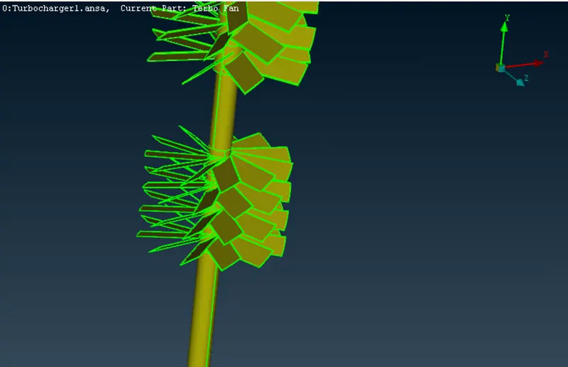
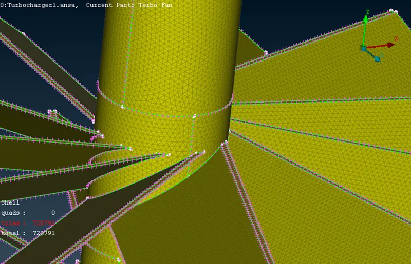
- Shaft rotor = 1 mm
- Turbo casing = 5 mm
- Compressor casing = 5 mm
- Inlet casing cover = 5 mm
Compressor casing
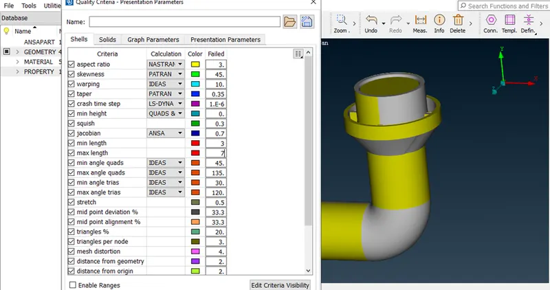
Min and max size is defined for the mesh.
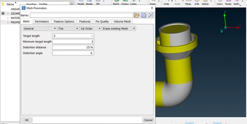
Target mesh size is defined then.
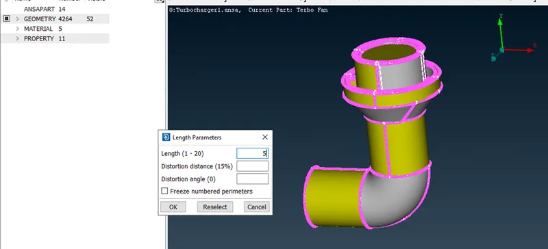
Macros and perimeters are further defined.
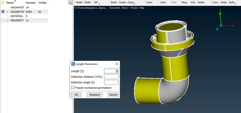
The meshed surface is available.
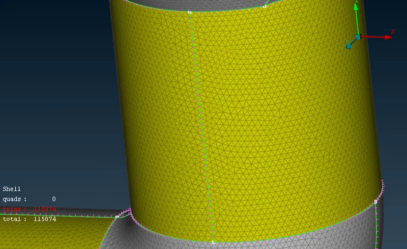
Inlet casing cover and Turbo casing (5mm)
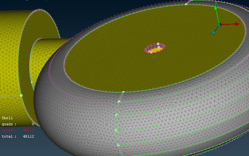
Bottom casing inlet and outlet (5mm)
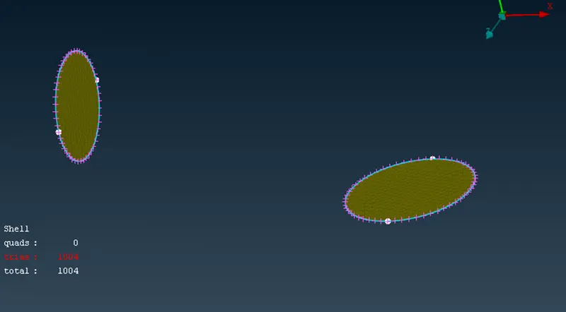
Impeller (2 mm)
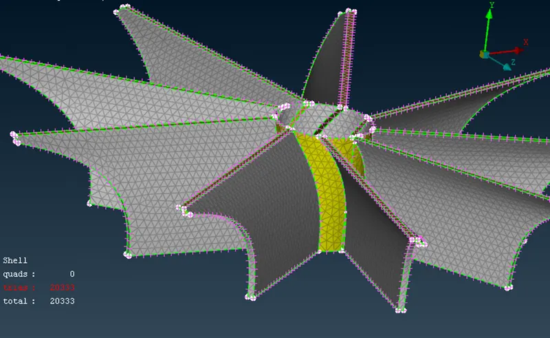
Blade stage-1 & 2, Shaft rotor (1mm)
Volumetric Mesh:
After completing the surface meshing, volumetric meshing is defined and the automatic volume identification is enabled.
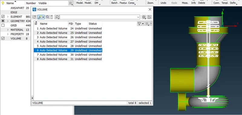
Deleting all the thckness volumes and keeping the inside volumes, gives us the remaining volumes a
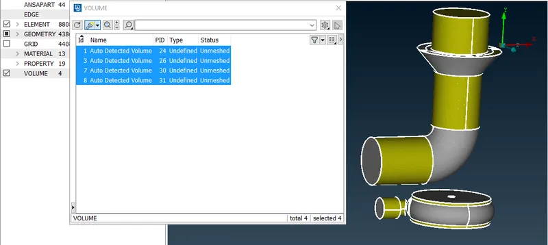
In the table, the meshing is not done. So, each volume is meshed by using the tetra CFD option and remeshing them further. All the meshed volumes are defined below.
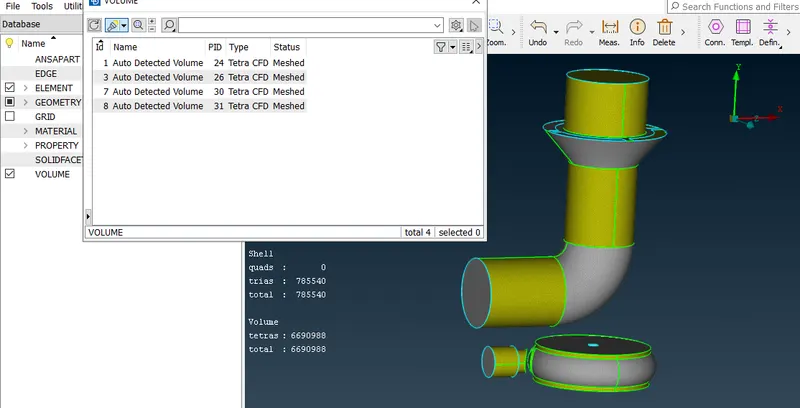
The finally available mesh can be observed in the section view of the volumes.
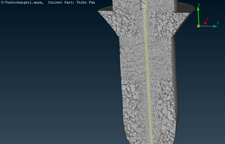
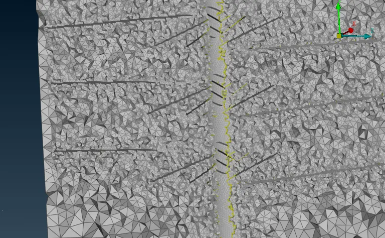
The zoom in view of the volume is shown below.
The lower casing is also meshed properly.
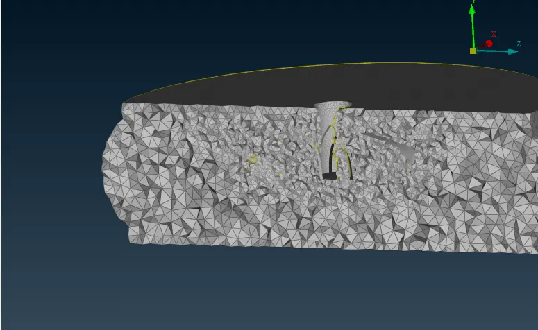
From the final zooming in view it can thus be observed that the mesh size is smaller near the blades and the shaft whose size is 1mm. So the mesh refinement based on the boundary mesh is done successful. As we go away from the inner shaft the mesh size seems to be increasing as the defined size is 5mm near there.
So, the Turbocharger is meshed by using the TETRA Elements and the meshing is done by keeping the different mesh sizes in consideration.