Week 8 - BlockMesh Drill down challenge
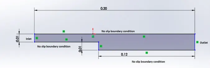
In this challenge, the objective was to simulate an incompressible-laminar-viscous flow through the backward facing step geometry, transient simulation is performed. The openFoam software tool was used in ubuntu OS.
OpenFOAM (for "Open-source Field Operation And Manipulation") is a C++ toolbox for the development of customized numerical solvers, and pre-/post-processing utilities for the solution of continuum mechanics problems, most prominently including computational fluid dynamics (CFD). It is one of the most versatile tool used in the industry to solve and simulate the real world problem.
The main objectives in this challange were:
Case 1 - Simulate the flow without using any grading factor (i.e., GF = 1)
Case 2 - Simulate the flow with grading factor of 0.2. The cells should be finer near the walls (includig the step wall).
The geometry is shown as:
The above two cases are solved as shown below by making the changes in the Tutorials available in the Tutorial folder of Openfoam directory.
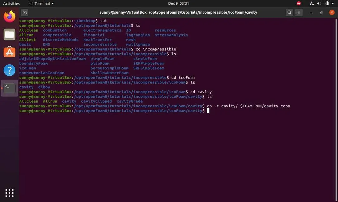
Case 1- In this case, the steps to copy the file from the tutorial:
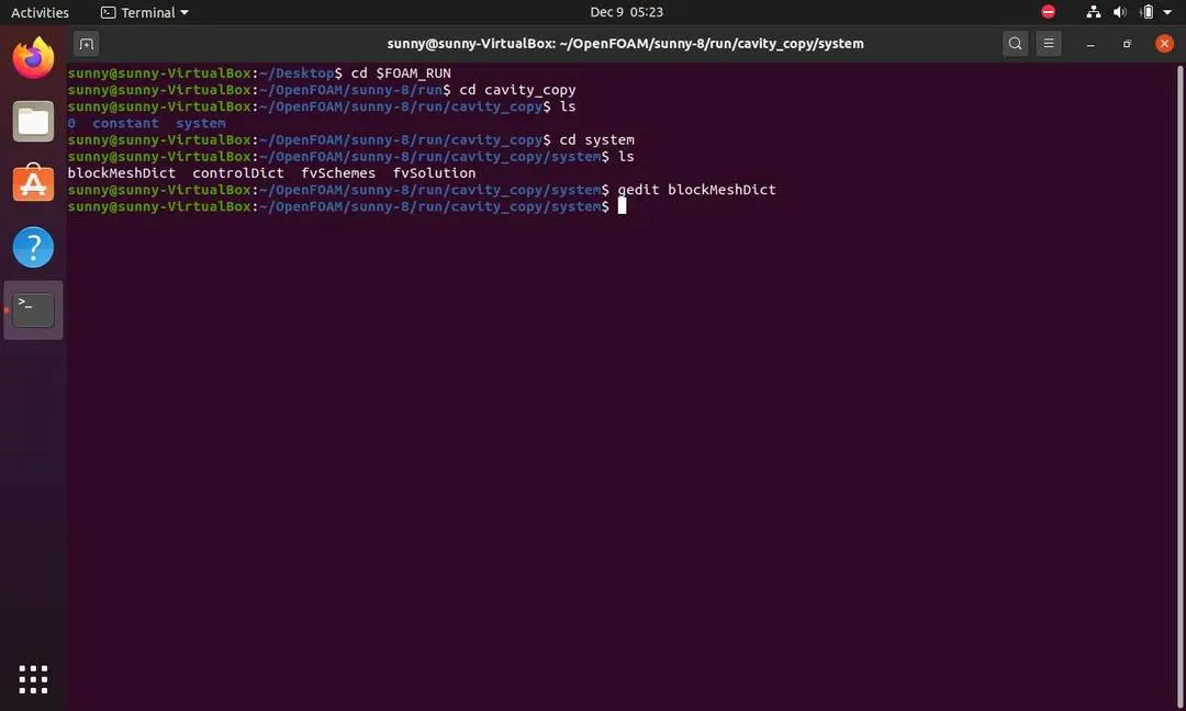
The steps to acess the files to edit the tutorial are:
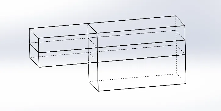
In the blockMeshDIct file the the geometry is defined and the meshing is further defined . The 3d view of the geometry and dividing it in parts is shown in following images.
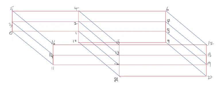
The final Blockmeshdict file after making changes is shown below and the changes are also explained:
/*--------------------------------*- C++ -*----------------------------------*
  =========                 |
  \      /  F ield         | OpenFOAM: The Open Source CFD Toolbox
   \    /   O peration     | Website:  https://openfoam.org
    \  /    A nd           | Version:  8
     \/     M anipulation  |
*---------------------------------------------------------------------------*/
FoamFile
{
    version     2.0;
    format      ascii;
    class       dictionary;
    object      blockMeshDict;
}
// * * * * * * * * * * * * * * * * * * * * * * * * * * * * * * * * * * * * * //

convertToMeters 0.01;

vertices
(
    (0 0 0)        //0
    (8 0 0)        //1
    (8 0.5 0)      //2
    (0 0.5 0)      //3
    (8 1 0)        //4
    (0 1 0)        //5
    (20 1 0)       //6
    (20 0.5 0)     //7
    (20 0 0)       //8
    (20 -1 0)      //9
    (8 -1 0)       //10
    (0 0 0.1)      //11
    (8 0 0.1)      //12
    (8 0.5 0.1)    //13
    (0 0.5 0.1)    //14
    (8 1 0.1)      //15
    (0 1 0.1)      //16
    (20 1 0.1)     //17
    (20 0.5 0.1)   //18
    (20 0 0.1)     //19
    (20 -1 0.1)    //20
    (8 -1 0.1)     //21

);

blocks
(
    hex (0 1 2 3 11 12 13 14) (80 5 1) simpleGrading (1 1 1)
    hex (3 2 4 5 14 13 15 16) (80 5 1) simpleGrading (1 1 1)

    hex (2 7 6 4 13 18 17 15) (120 5 1) simpleGrading (1 1 1)

    hex (1 8 7 2 12 19 18 13) (120 5 1) simpleGrading (1 1 1)

    hex (10 9 8 1 21 20 19 12) (120 10 1) simpleGrading (1 1 1)
);

edges
(
);

boundary
(
    inlet
    {
        type wall;
        faces
        (
            (0 11 14 3)
            (3 14 16 5)
        );
    }
    outlet
    {
        type wall;
        faces
        (
            (9 8 19 20)
            (8 7 18 19)
            (7 6 17 18)

        );
    }
    fixed
    {
        type wall;
        faces
        (
            (4 5 16 15)
            (6 4 15 17)
            (12 11 0 1)
            (12 1 10 21)
            (10 9 20 21)
        );
    }
    frontAndBack
    {
        type empty;
        faces
        (
            (14 13 15 16)
            (11 12 13 14)
            (21 20 19 12)
            (19 18 13 12)
            (13 18 17 15)
            (3 5 4 2)
            (0 3 2 1)
            (2 4 6 7)
            (1 2 7 8)
            (10 1 8 9)
       );
    }
);

mergePatchPairs
(
);

// ************************************************************************* //
The vertices block in the above file is the main sub block as it defines the points of our geometry. As this is written in ordered form automatically and the points are used to make block and faces in below code.
The blocks defines the number of blocks we require . and for this problem we divide the complete diagram into 5blocks as shown in image above.
Next The boundary defines various walls ie. Inlet, Outlet, fixed(Top and Bottom), topAndBottom.
Now The inlet conditions are changed and the values of Initial pressure and velocity are changed:
Pressure
/*--------------------------------*- C++ -*----------------------------------*
  =========                 |
  \      /  F ield         | OpenFOAM: The Open Source CFD Toolbox
   \    /   O peration     | Website:  https://openfoam.org
    \  /    A nd           | Version:  8
     \/     M anipulation  |
*---------------------------------------------------------------------------*/
FoamFile
{
    version     2.0;
    format      ascii;
    class       volVectorField;
    object      U;
}
// * * * * * * * * * * * * * * * * * * * * * * * * * * * * * * * * * * * * * //

dimensions      [0 1 -1 0 0 0 0];

internalField   uniform (0 0 0);

boundaryField
{
    inlet
    {
        type            fixedValue;
        value           uniform (1 0 0);
    }
    outlet
    {
        type            zeroGradient;
    }

    fixed
    {
        type            noSlip;
    }

    frontAndBack
    {
        type            empty;
    }
}

// ************************************************************************* //
In the above file of Pressure boundary condtion at every face is given as:
1. Inlet- Since the inlet should be always const. and it should have a fixed value, so the inlet pressure is 1m/s in 1D.
2. Outlet - The outlet is to be calculated and thus we define it as a ZeroGradient condition as there should be no change with respect with time as continuous output is preferred.
3. Fixed - Since there should be no effect of the walls of top and bottom we define as noslip condition as there should be no Boundary layer development.
4. Front and Back - since due to its 2D study there should be no effect in 3rd dimension it is set as empty.
Velocity
/*--------------------------------*- C++ -*----------------------------------*
  =========                 |
  \      /  F ield         | OpenFOAM: The Open Source CFD Toolbox
   \    /   O peration     | Website:  https://openfoam.org
    \  /    A nd           | Version:  8
     \/     M anipulation  |
*---------------------------------------------------------------------------*/
FoamFile
{
    version     2.0;
    format      ascii;
    class       volVectorField;
    object      U;
}
// * * * * * * * * * * * * * * * * * * * * * * * * * * * * * * * * * * * * * //

dimensions      [0 1 -1 0 0 0 0];

internalField   uniform (0 0 0);

boundaryField
{
    inlet
    {
        type            fixedValue;
        value           uniform (1 0 0);
    }
    outlet
    {
        type            zeroGradient;
    }

    fixed
    {
        type            noSlip;
    }

    frontAndBack
    {
        type            empty;
    }
}

// ************************************************************************* //
The values at different faces are said to have a similar explanation as discussed in case of pressure.
ControlDict
/*--------------------------------*- C++ -*----------------------------------*
  =========                 |
  \      /  F ield         | OpenFOAM: The Open Source CFD Toolbox
   \    /   O peration     | Website:  https://openfoam.org
    \  /    A nd           | Version:  8
     \/     M anipulation  |
*---------------------------------------------------------------------------*/
FoamFile
{
    version     2.0;
    format      ascii;
    class       dictionary;
    location    "system";
    object      controlDict;
}
// * * * * * * * * * * * * * * * * * * * * * * * * * * * * * * * * * * * * * //

application     icoFoam;

startFrom       startTime;

startTime       0;

stopAt          endTime;

endTime         0.5;

deltaT          0.0001;

writeControl    timeStep;

writeInterval   20;

purgeWrite      0;

writeFormat     ascii;

writePrecision  6;

writeCompression off;

timeFormat      general;

timePrecision   6;

runTimeModifiable true;


// ************************************************************************* //
After setting up all the parameters, to check about the meshing command blockMesh is eecuted in terminal and then paraFoam command. The structure in result we got is:
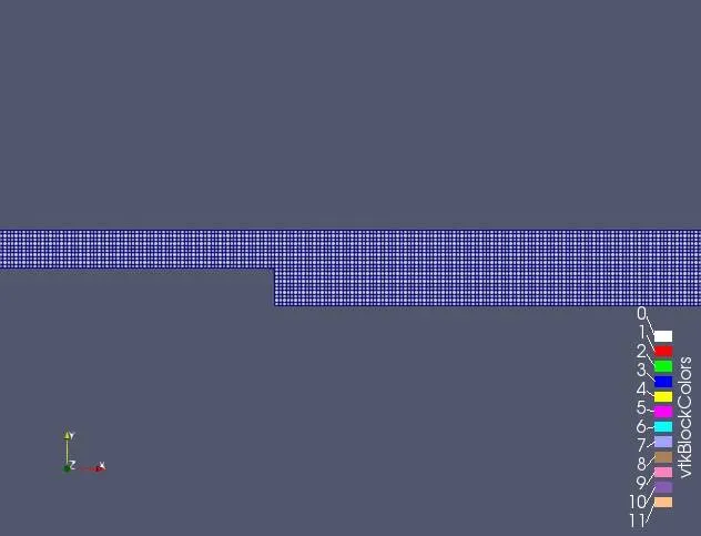
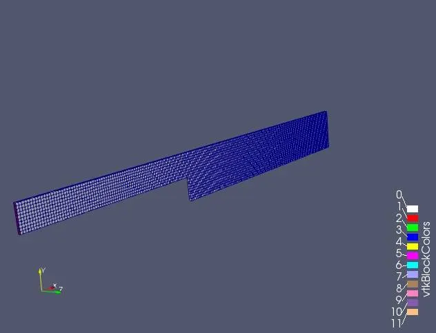
As it can be observed that mesh is completely fine and equal along X and Y.
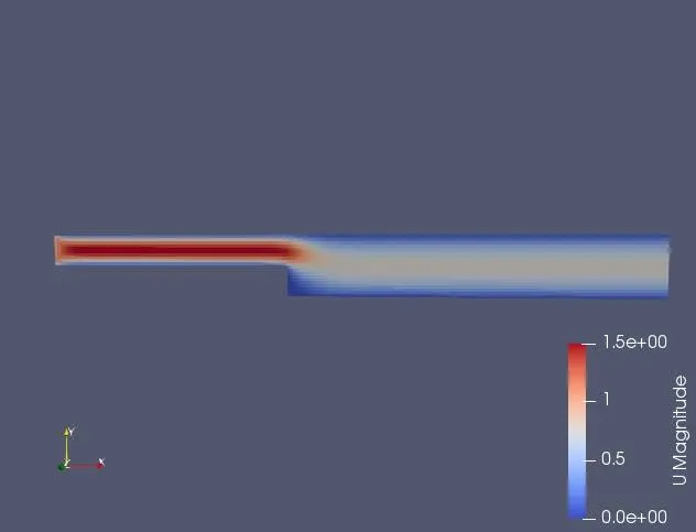
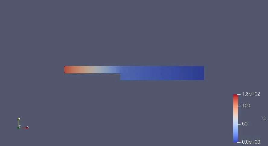
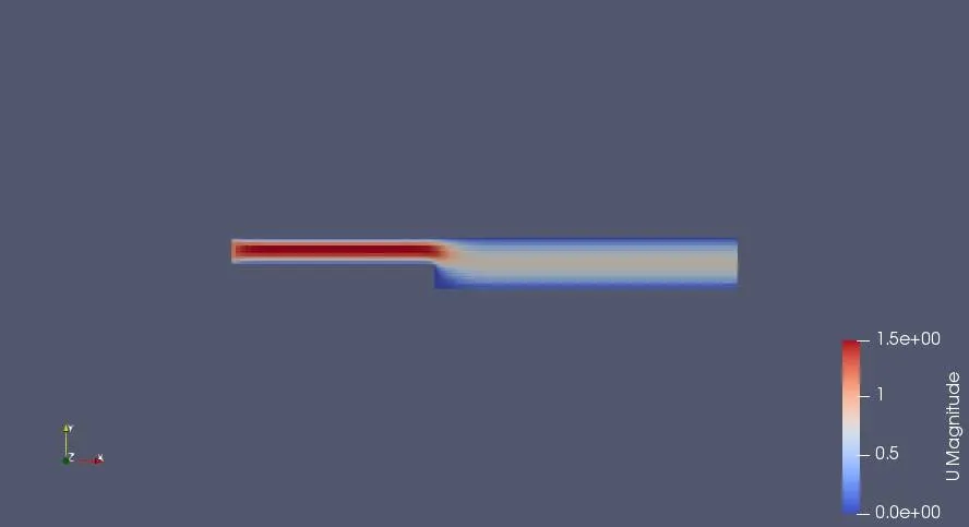
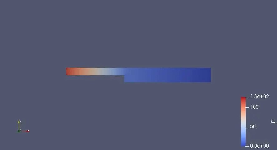
After Observing mesh, The icoFoam solver is made to run. And in result we get the output in paraview window by paraFoam command. we get the prssure and velocity distribution as:
Velocity variation along length:
Pressure variation along length:
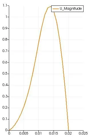
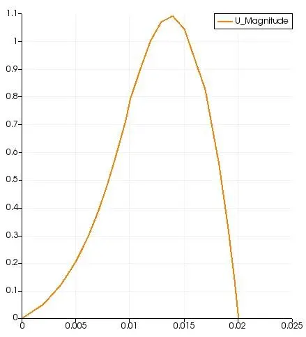
The velocity profile at a distance of 0.085 m near the step from inlet is given as-
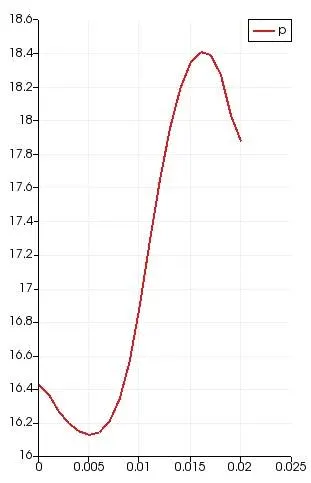
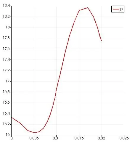
The pressure profile at a distance of 0.085 m near the step from inlet is given as-
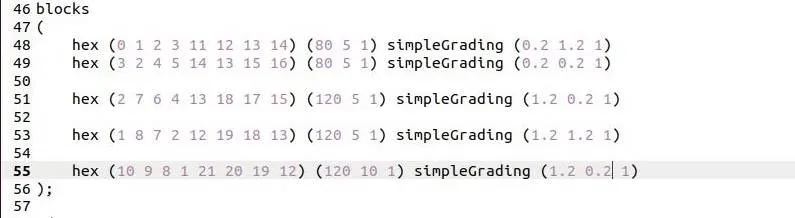
Case 2- For a grading factor of 0.2. The whole code for this is same only there is change in grading of mesh. The changes are made in blockMeshDict file as:
The mesh obtained in this case is:
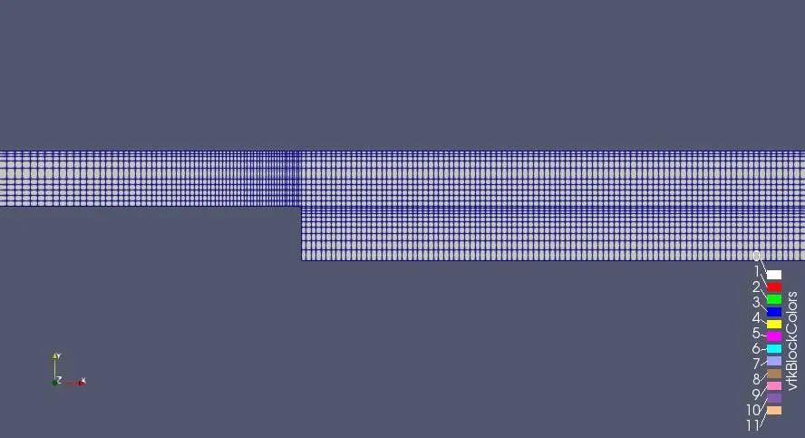
It is easily incurred that the mesh is mainly concentrated near the step wall, and the corners to achieve more accuracy.
The distributions are-
Velocity variation along length:
Pressure variation along length:
The velocity profile at a distance of 0.085 m near the step from inlet is given as-
The pressure profile at a distance of 0.085 m near the step from inlet is given as-
 .
.
Comparision of two cases:
| Mesh Grading Factor | Pressure at 0.085m from inlet | Velocity at 0.085m from inlet | Execution time of Simulation |
| 1 | 16.455 | 0.574203 | 38 sec |
| 0.2 | 16.26005 | 0.56359 | 38.84 sec |
From the above comparision, it can be concluded that-
1. By having a non-linear/inconsitent mesh grading or different mesh size, the execution time got increased.
2. After having a more mesh points at critical areas, we get more accurate results as we achieve near to real life results.