Week 3 Challenge : CFD meshing on Turbocharger
1. Introduction
The main objective of the challenge is to perform a Topology Cleanup and mesh the given geometry of a Turbocharger with different mesh length elements to understand the variation in the mesh lengths which is to be forwarded for physics simulations. Also to perform the Volumetric Mesh as per the reference videos.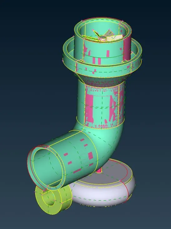
2. Procedure to Mesh
This section is differentiated into following subsections for the procedures of meshing different components of the Turbocharger.
2.1. Topology Cleanup for Geometry
Sometimes upon importing a geometry into ANSA there will be cases of missing faces, inconsistent edges overlapping or hole formation on the geometry surface which are undesirable. This is set to be cleaned up to perform mesh by using the topology Clean up methods.
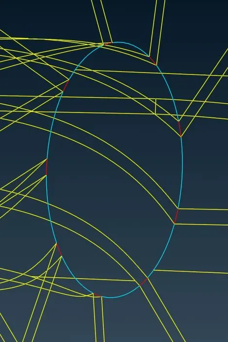
These inconsistencies in ANSA can be identified by looking for edges with a red colour indicating a requirement for cleanup.
- After completing the initial Geometry Checks, the intersecting regions are to be looked for from the TOPO deck.
- Upon getting the list of errors from the imported geometry, each error can be seen in the geometry by clicking on the errors individually for easier understanding and differentiation.
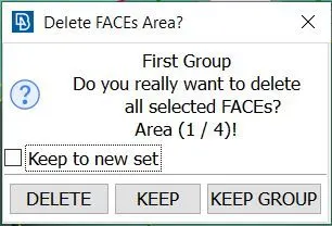
- For the Overlapping faces, these overlapping faces are to be deleted. After entering PID mode, the different faces are observed to be represented in different colors. In this case, green and pink are represented. from this as pink surface is observed to be overlapping. For this, the green surfaces are hide so the pink colored surface is left which is deleted.
- For sections where void spaces are created due to this overlapping of faces. For this the overlapping face is deleted. To fill the void created, FILL HOLE option is selected. This is done to solve the inconsistences on the geometry faces.
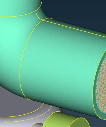
- Sometimes, the FILL HOLE option shows inconsistencies as the edges that are to be used has inconsistencies in it as a root cause for improper face formation. For this, INSERT HOT POINTS option is used to insert hot points in-order to get the desired edge lengths. Upon using this, FILL HOLE is implemented.
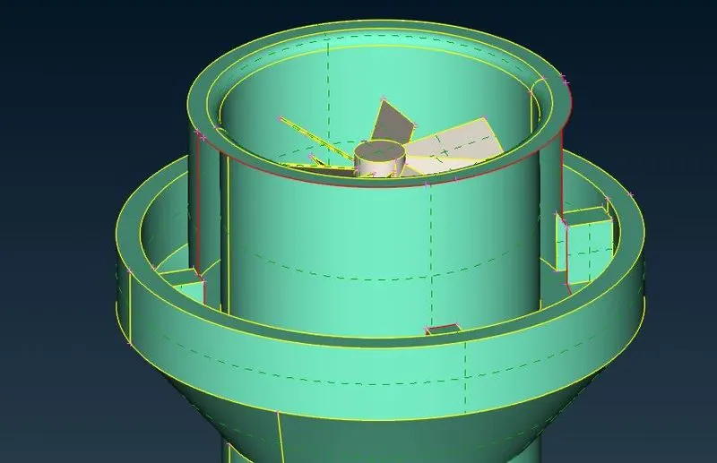
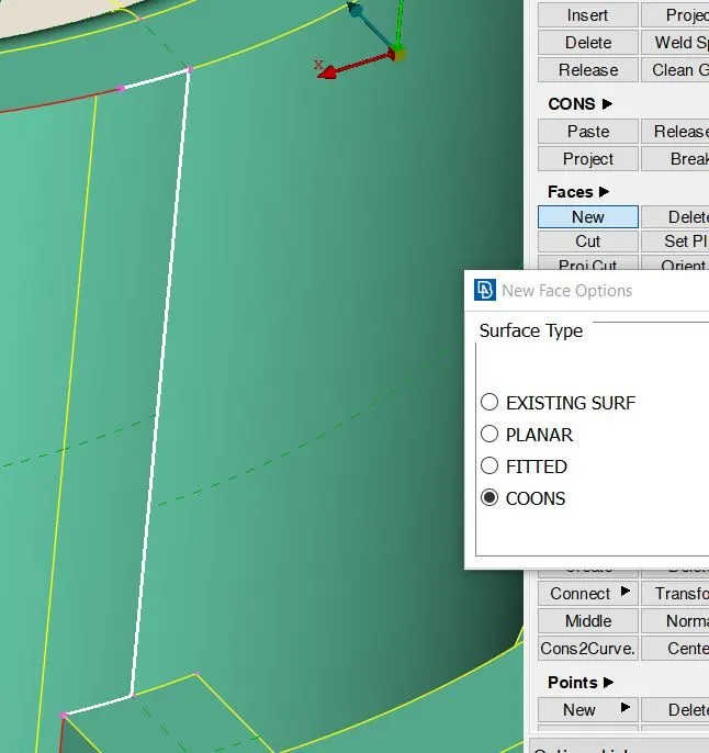
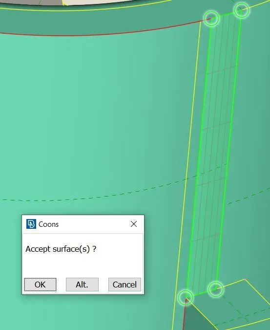
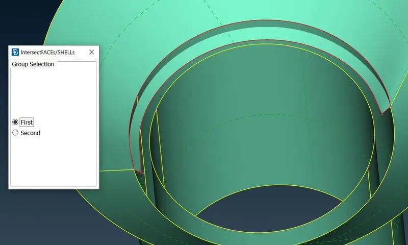
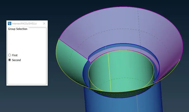
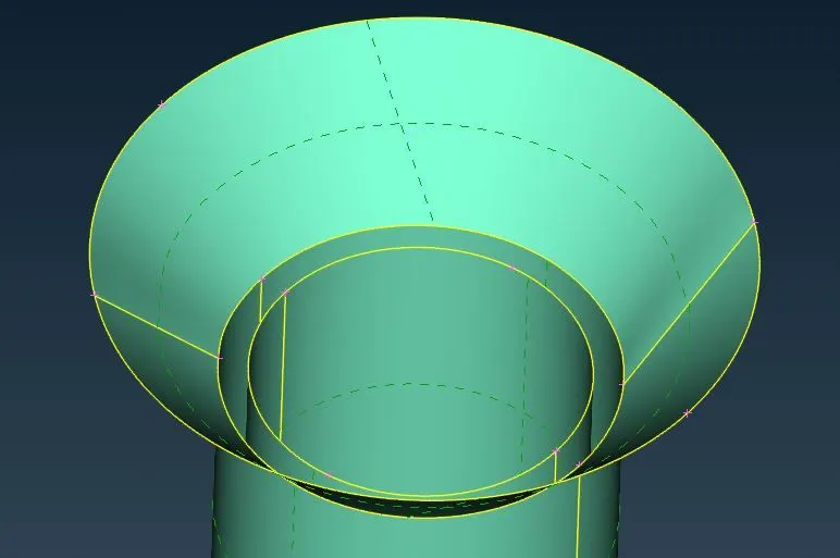
- Some surfaces are observed to be intersecting with each other. To solve this issue, the INTERSECT option is utilized. Upon using this option, these intersecting faces are selected and the unnecessary faces are deleted.
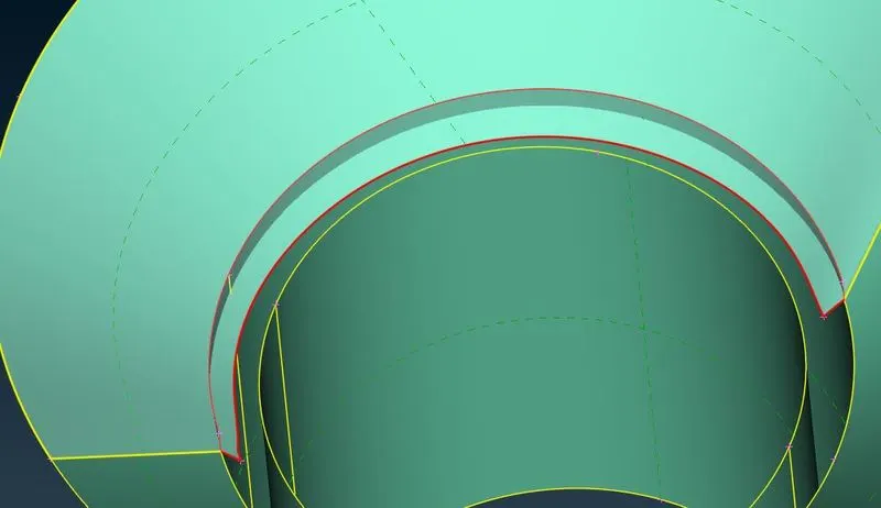
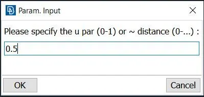
- This is used to create hot points on an existing cons. Select PARAMETRICAL option. It asks you to specify the distance as it assumes the distance is between the rangge of 0 - 1. For this 0.5 is to be assigned.
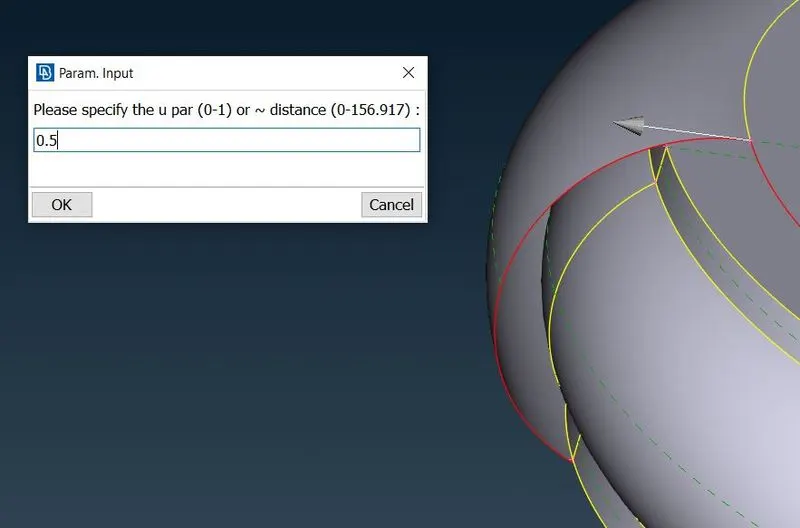
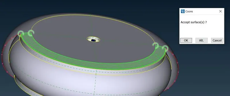
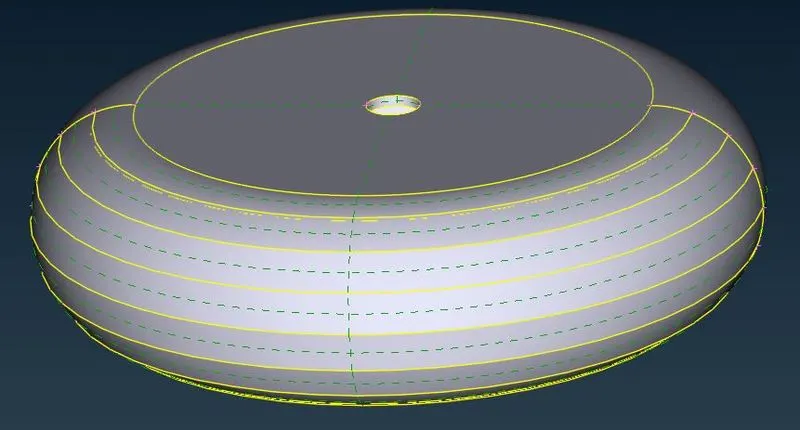
- Removal of some faces as aforementioned is difficult as it forms further inconsistencies. In this case, HOT POINTS are created and are Projected using PROJECT option which projects these hot points to the selected edges and faces. Upon creating these hot points, the overlapping faces are deleted and the remaining voids are filled using methods aforementioned.
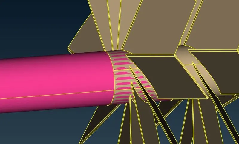
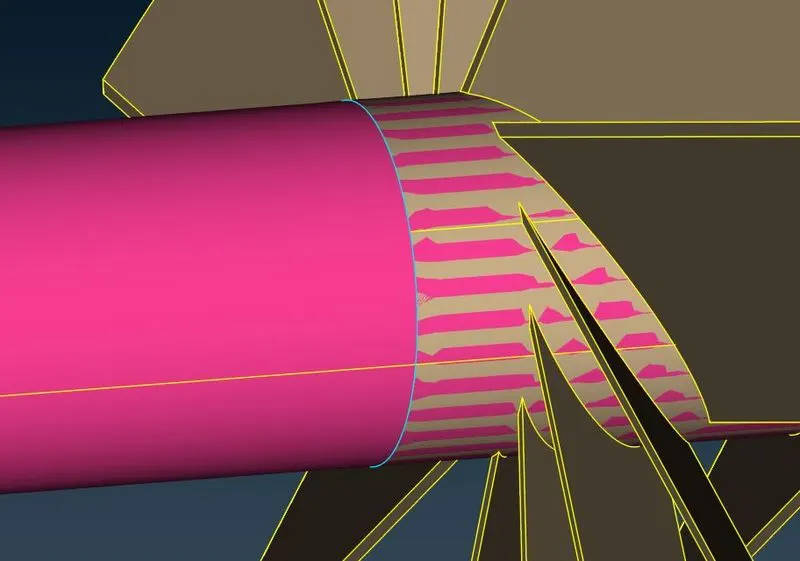
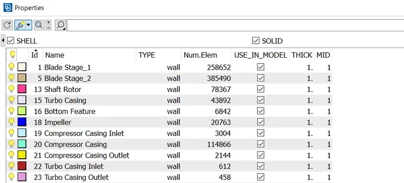
- PIDs are to be assigned at the end of the cleanup procedure to differentiate the Shell and Solid components of the geometry which can be done in the PID section as represented below. This property assignment is indicated in different colors for a better understanding.
2.2. Meshing for Geometry
For this particular Geometry, different components of it are to be assigned with different Mesh Lengths as per the challenge. This is in regards with the observed from the previous challenge, the Mesh Lengths are based on the dimensions of the components as smaller components with larger Mesh Length results in coarse mesh quality which is not suitable for capturing the physics of the geometry.
The assigned Mesh Length values for the components is as follows:
- Blade stage-1: 1 mm
- Blade stage-2: 1 mm
- Impeller: 2 mm
- Shaft Rotor: 1 mm
- Turbo Casing: 5 mm
- Compressor Casing: 5 mm
- Inlet Casing Cover: 5 mm
2.2.1. Blade Stage-1 Mesh:
- To assign the target length of 1 mm for mesh, it is also necessary to provide the Minimum and Maximum Lengths for the same in-order to get the mesh lengths as close to as possible to the target length. For this, a minimum of 0.5 mm and a maximum of 2 mm have been considered.
- These values are to be specified in both Mesh parameters as well as Quality Criteria as shown below.
- As per the challenge, the mesh element type is to be set to TRIA which can be setup in the Mesh Parameters Section as shown above.
- The Mesh Lengths are to be setup in the LENGTH option which opens a pop-up window with sections of PERIMETER and MACROS. The target Length is to be specified in both the sections as per the representation below.
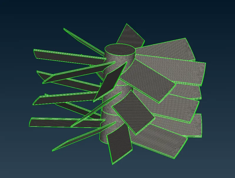
- Though the entire geometry can be meshed at a go, each individual PID region has been meshed separately in this case in-order to understand the continuity of the Mesh and look for any issues with the generated mesh. It is done using SPOT MESH option in MESH GENEREATION SECTION.
2.2.2. Blade Stage-2 Mesh:
- To assign the target length of 1 mm for mesh, it is also necessary to provide the Minimum and Maximum Lengths for the same in-order to get the mesh lengths as close to as possible to the target length. For this, a minimum of 0.5 mm and a maximum of 2 mm have been considered.
- These values are to be specified in both Mesh parameters as well as Quality Criteria as shown below.
- As per the challenge, the mesh element type is to be set to TRIA which can be setup in the Mesh Parameters Section as shown above.
- The Mesh Lengths are to be setup in the LENGTH option which opens a pop-up window with sections of PERIMETER and MACROS. The target Length is to be specified in both the sections as per the representation below.
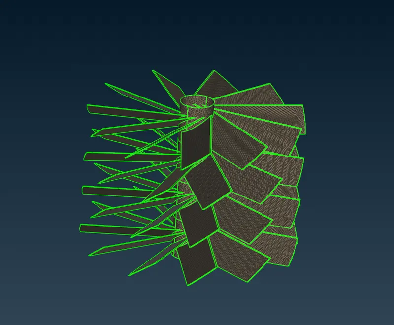
- Though the entire geometry can be meshed at a go, each individual PID region has been meshed separately in this case in-order to understand the continuity of the Mesh and look for any issues with the generated mesh. It is done using SPOT MESH option in MESH GENEREATION SECTION.
2.2.3. Impeller Mesh:
- To assign the target length of 2 mm for mesh, it is also necessary to provide the Minimum and Maximum Lengths for the same in-order to get the mesh lengths as close to as possible to the target length. For this, a minimum of 1 mm and a maximum of 3 mm have been considered.
- These values are to be specified in both Mesh parameters as well as Quality Criteria as shown below.
- As per the challenge, the mesh element type is to be set to TRIA which can be setup in the Mesh Parameters Section as shown above.
- The Mesh Lengths are to be setup in the LENGTH option which opens a pop-up window with sections of PERIMETER and MACROS. The target Length is to be specified in both the sections as per the representation below.
- Though the entire geometry can be meshed at a go, each individual PID region has been meshed separately in this case in-order to understand the continuity of the Mesh and look for any issues with the generated mesh. It is done using SPOT MESH option in MESH GENEREATION SECTION.
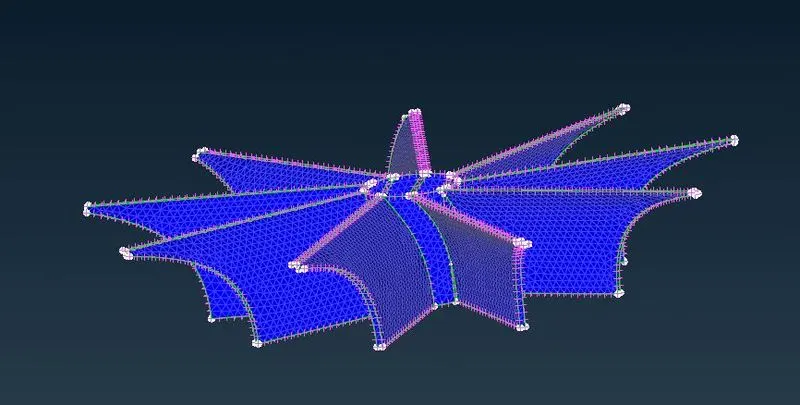
2.2.4. Shaft Rotor:
- To assign the target length of 1mm for mesh, it is also necessary to provide the Minimum and Maximum Lengths for the same in-order to get the mesh lengths as close to as possible to the target length. For this, a minimum of 0.5 mm and a maximum of 2 mm have been considered.
- These values are to be specified in both Mesh parameters as well as Quality Criteria as shown below.
- As per the challenge, the mesh element type is to be set to TRIA which can be setup in the Mesh Parameters Section as shown above.
- The Mesh Lengths are to be setup in the LENGTH option which opens a pop-up window with sections of PERIMETER and MACROS. The target Length is to be specified in both the sections as per the representation below.
- Though the entire geometry can be meshed at a go, each individual PID region has been meshed separately in this case in-order to understand the continuity of the Mesh and look for any issues with the generated mesh. It is done using SPOT MESH option in MESH GENEREATION SECTION.
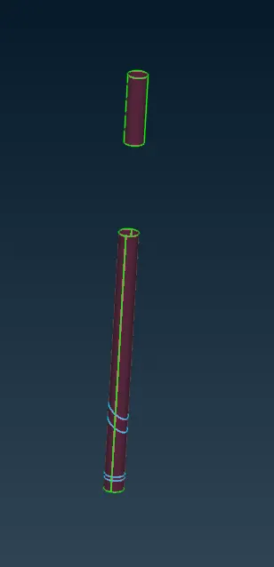
2.2.5. Turbo Casing:
- To assign the target length of 5 mm for mesh, it is also necessary to provide the Minimum and Maximum Lengths for the same in-order to get the mesh lengths as close to as possible to the target length. For this, a minimum of 3 mm and a maximum of 7 mm have been considered.
- These values are to be specified in both Mesh parameters as well as Quality Criteria as shown below.
- As per the challenge, the mesh element type is to be set to TRIA which can be setup in the Mesh Parameters Section as shown above.
- The Mesh Lengths are to be setup in the LENGTH option which opens a pop-up window with sections of PERIMETER and MACROS. The target Length is to be specified in both the sections as per the representation below.
- Though the entire geometry can be meshed at a go, each individual PID region has been meshed separately in this case in-order to understand the continuity of the Mesh and look for any issues with the generated mesh. It is done using SPOT MESH option in MESH GENEREATION SECTION.
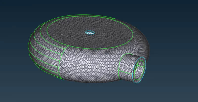
2.2.6. Compressor Casing:
- To assign the target length of 5 mm for mesh, it is also necessary to provide the Minimum and Maximum Lengths for the same in-order to get the mesh lengths as close to as possible to the target length. For this, a minimum of 3 mm and a maximum of 7 mm have been considered.
- These values are to be specified in both Mesh parameters as well as Quality Criteria as shown below.
- As per the challenge, the mesh element type is to be set to TRIA which can be setup in the Mesh Parameters Section as shown above.
- The Mesh Lengths are to be setup in the LENGTH option which opens a pop-up window with sections of PERIMETER and MACROS. The target Length is to be specified in both the sections as per the representation below.
- Though the entire geometry can be meshed at a go, each individual PID region has been meshed separately in this case in-order to understand the continuity of the Mesh and look for any issues with the generated mesh. It is done using SPOT MESH option in MESH GENEREATION SECTION.
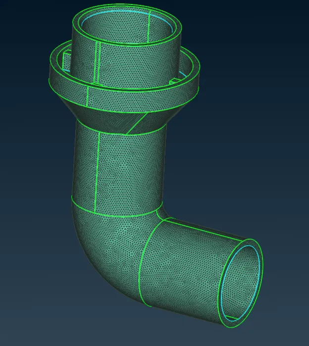
2.2.7. Inner Casing Cover:
- To assign the target length of 5 mm for mesh, it is also necessary to provide the Minimum and Maximum Lengths for the same in-order to get the mesh lengths as close to as possible to the target length. For this, a minimum of 3 mm and a maximum of 7 mm have been considered.
- These values are to be specified in both Mesh parameters as well as Quality Criteria as shown below.
- As per the challenge, the mesh element type is to be set to TRIA which can be setup in the Mesh Parameters Section as shown above.
- The Mesh Lengths are to be setup in the LENGTH option which opens a pop-up window with sections of PERIMETER and MACROS. The target Length is to be specified in both the sections as per the representation below.
- Though the entire geometry can be meshed at a go, each individual PID region has been meshed separately in this case in-order to understand the continuity of the Mesh and look for any issues with the generated mesh. It is done using SPOT MESH option in MESH GENEREATION SECTION.
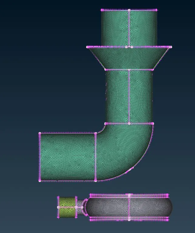
2.3. Volumetric Meshing for Geometry
- Volumetric Meshing is used to mesh the volume of the geometry which is further used in the CFD simulation. This can be done in ANSA by selecting V. MESH from the Deck.
- To start with volumetric meshing, DEFINE option is selected in the VOLUME option leading to opening a pop-up for Volumetric Detection requiring a detection for Whole Database to mesh. The prompt of requiring a surface mesh can be ignored as Surface Mesh is already done. Selecting OK will open up a pop-up window with all the volumes from the geometry.
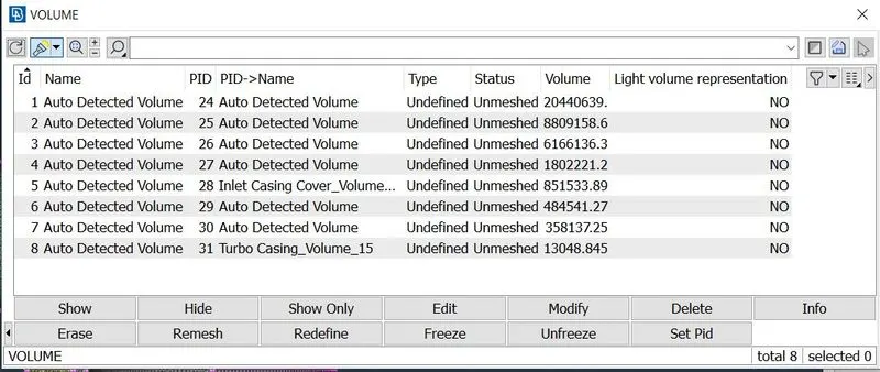
- Alongside main requirement all the other volumes are also generated which are not required as the fluid doesn't flow through it. So, these additional volumes are deleted by confirming with the previews generated.
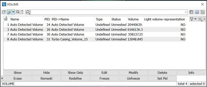
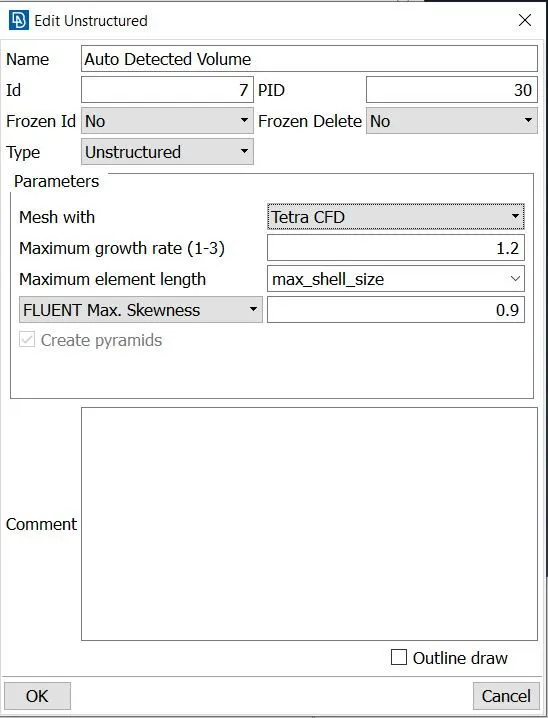
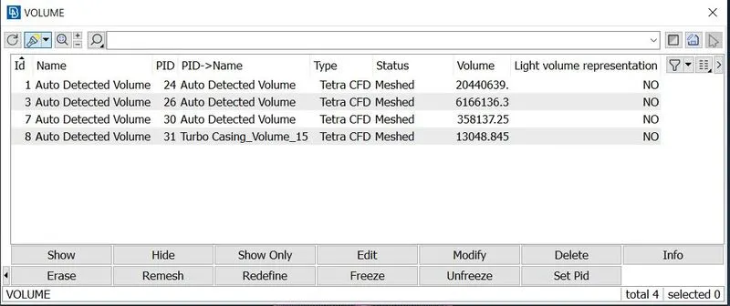
- The Mesh status can still be observed to be Unmeshed as the Mesh Domain is to be specified. In this case, the Mesh Domain is set to "Tetra CFD" and is remeshed. The updated mesh window can be observed as below.
3. Conclusion
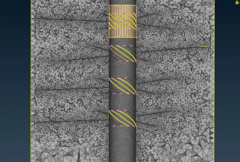
The objective of performing a Topology Cleanup and mesh the geometry of a Turbocharger with different mesh length elements assigned to their respective PID region to get variation in the mesh lengths has been performed and also the volumetric Mesh for the same has been performed. The output representation is as shown below and the supporting Model File has been linked below.
Model Link: Challenge - 3: CFD Meshing on Turbocharger