Week 3 Challenge : CFD meshing on Turbocharger
Aim:
To generate surface and volume mesh for the given turbocharger.
Objective:
To generate the tetra mesh over PID's, with different mesh element size. And to generate volume mesh inside the defined watertight geomentry.
Introduction:
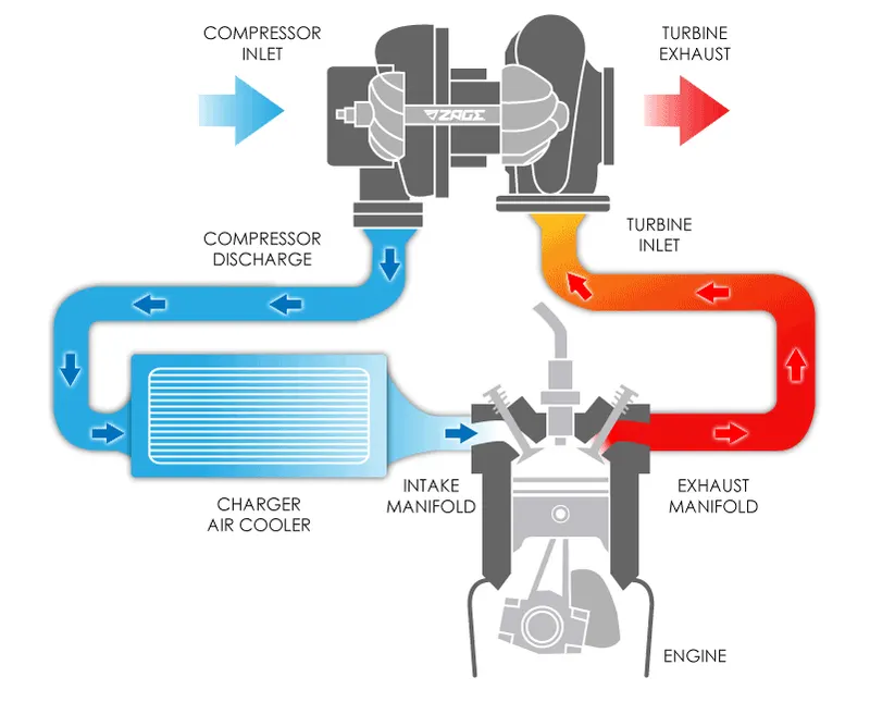
A turbocharger is a device fitted to a vehicle’s engine that is designed to improve the overall efficiency and increase performance. Turbochargers are a type of forced induction system that compresses the air flowing into the car's engine. The advantage of compressing the air is that it lets the engine squeeze more air into a cylinder, and more air means that more fuel can be added. Therefore, you get more power from each explosion in each cylinder.A turbocharged engine produces more power overall than the same size engine without the charging. This can significantly improve the power-to-weight ratio for the engine.
A turbocharger consists of a compressor wheel and exhaust gas turbine wheel coupled together by a solid shaft and that is used to boost the intake air pressure of an internal combustion engine. The exhaust gas turbine extracts energy from the exhaust gas and uses it to drive the compressor and overcome friction. In most automotive-type applications, both the compressor and turbine wheel are of the radial flow type.
Procedure :
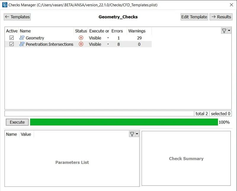
We import the given turbocharger geomentry to space claim. First we clear the extra hot points and do a TOPO over the entire geomentry, this will ensure that if any two surfaces to have a prober contact between them, and this helps in possible clearing of some single CONS. Then we do the geomentry checkup to detect single CONS and intersection errors.
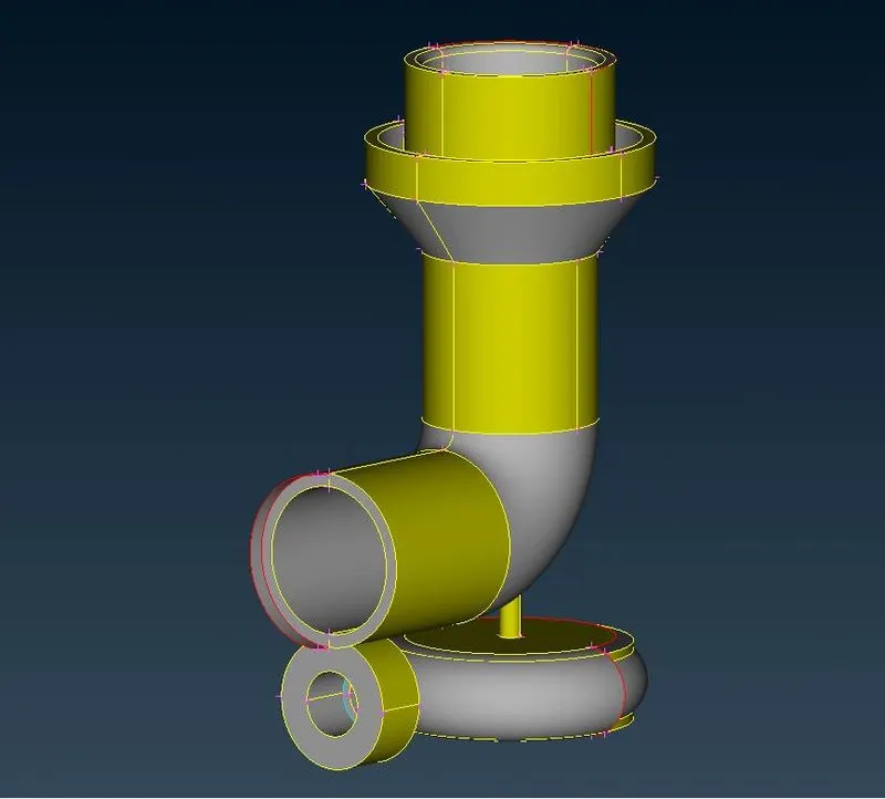
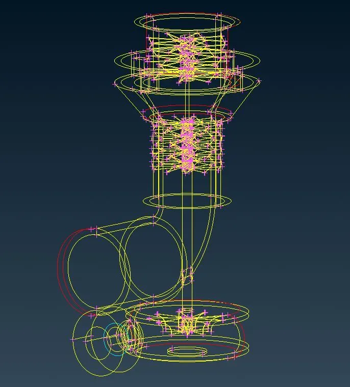
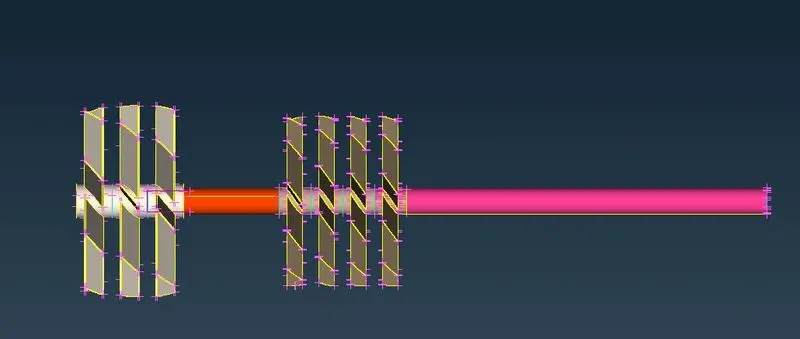
We first want to clear the single CONS , for that we use geomentry clean up tools like cut,new face creation, project, creating symmetric surface. We convert the single CONS to Double or tripple CONS, we deleted uneven surfaces, made sure that the geomentry have a completed surfaces throughout, an deleted un wanted surfaces. For the multiple triple CONS due to intersection of the shaft with other components, we cleared the overlaying surfaces and the shaft geomentry constituted as different geomentries we made the entire shaft as a single continuous geomentry by removing the surfaces inbetween. Also we use the project option to project the single CONS on to the surface of the other geomentry this converts them to double CONS.
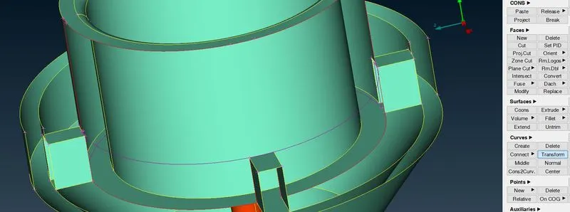
The transform Tool help us in creating a 3-D curve with the help of an existing curve near it, and by defining start and end point we were able to create a new curve this helps us to create a new surface over complex geometry with multiple curves.
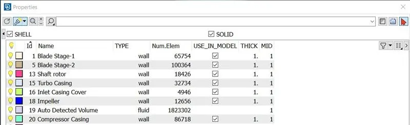
We then define the PIDs required, this process help us to easily identify parts and define the size of mesh indivudally for each components.
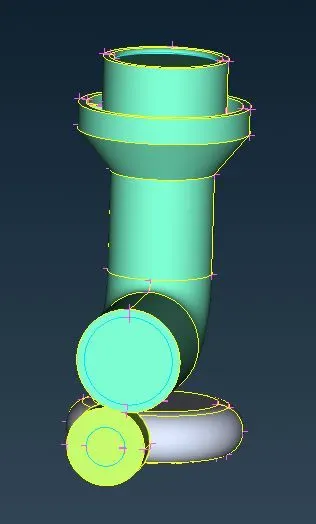
At this stage we have to ensure that there is no openings in the geomentry and all the gaps are are closed to make the watertight geometry, this enables us to define the wet volume region in the geometry, as it is easy for the solver to identify the region this way. We generate the surfavce mesh for each component. First we open the mesh properties and enter the maximum and minimum length of the element, this gives a range to the solver and it uses like tolerence to generate majority mesh element size between these values. The below mentioned range is for mesh size of 2 mm. The lesser the difference between the maximum and minimum values the better the mesh size close to required, accuracy and higher the computational time and power.
Before the mesh generation we need to make sure there is no erro in the geometry.
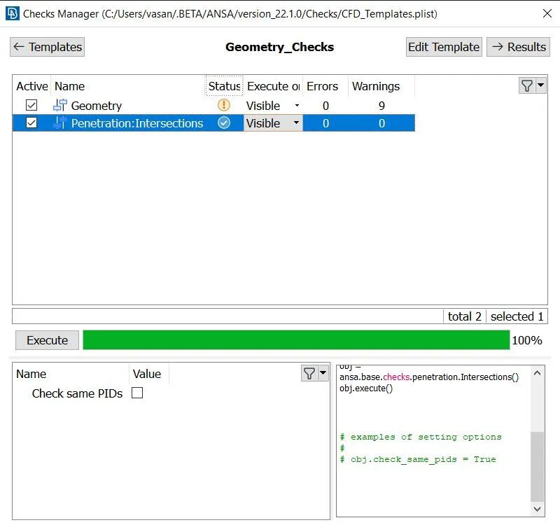
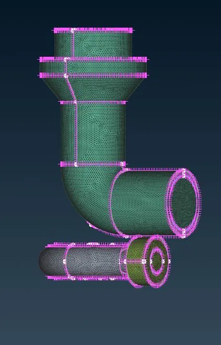
There is no error and it is only warning for tripple CONS which we can ignore. The mesh size for componetis is as follows,
- Blade stage-1 = 1 mm
- Blade stage-2 = 1 mm
- Impeller = 2 mm
- Shaft rotor = 1 mm
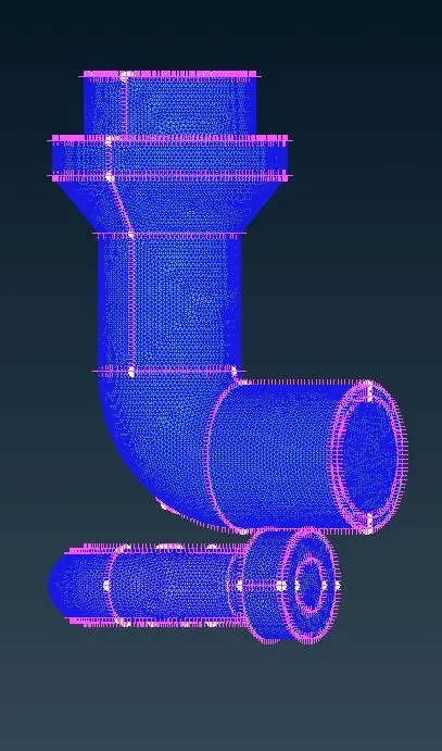
- Turbo casing = 5 mm
- Compressor casing = 5 mm
- Inlet casing cover = 5 mm
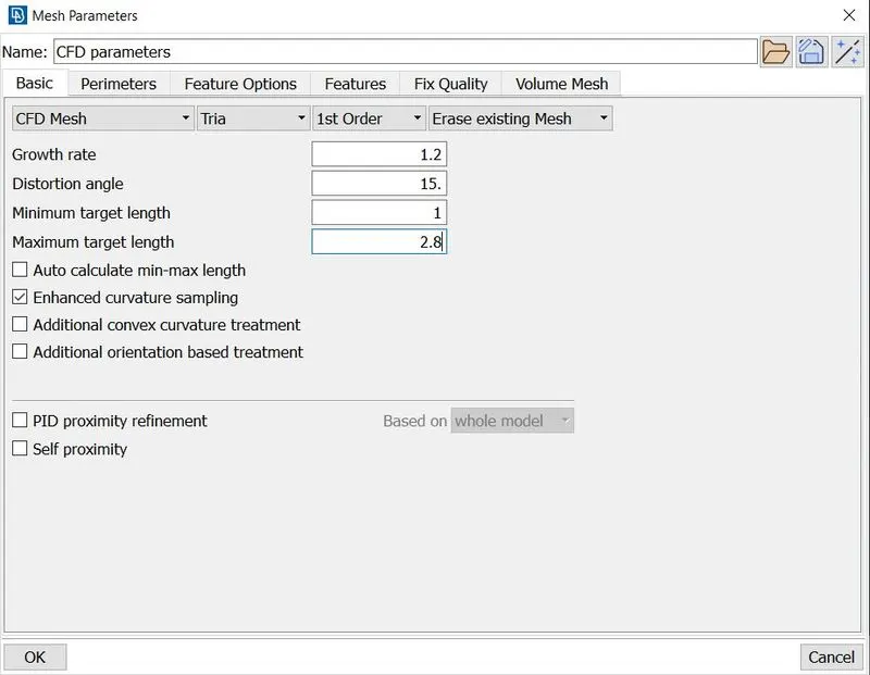
Then under perimeter we provide the same inputs and generate the CFD mesh for the given geomentry , this is repeated for every components, and before switching to next components we freeze the the mesh generated for the current. So, the mesh stays evene if we change the mesh size for the components that are in contact with this component.
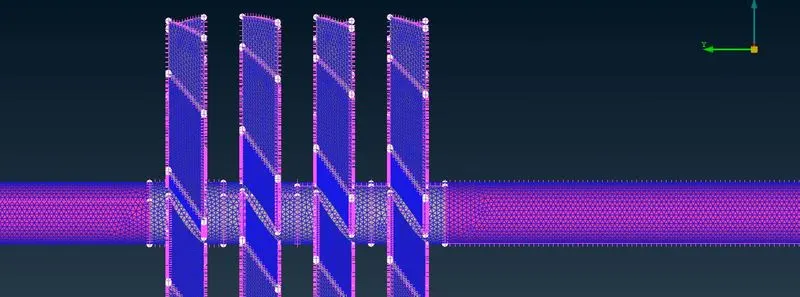
Mesh size of 5mm
Mesh size of 2 mm
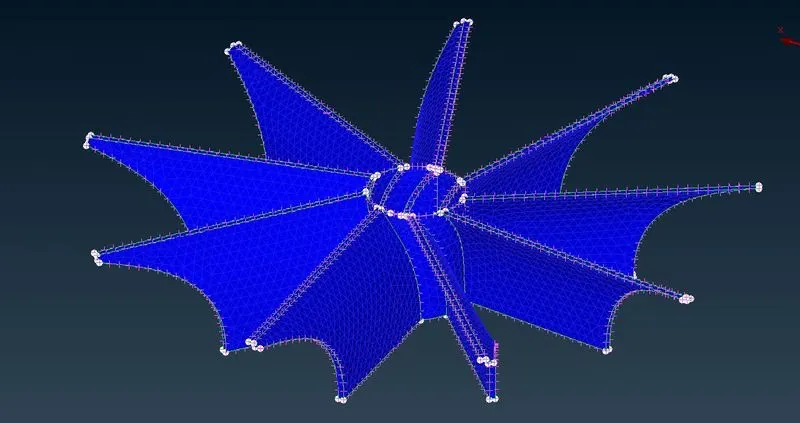
Mesh size of 1 mm
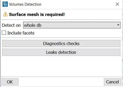
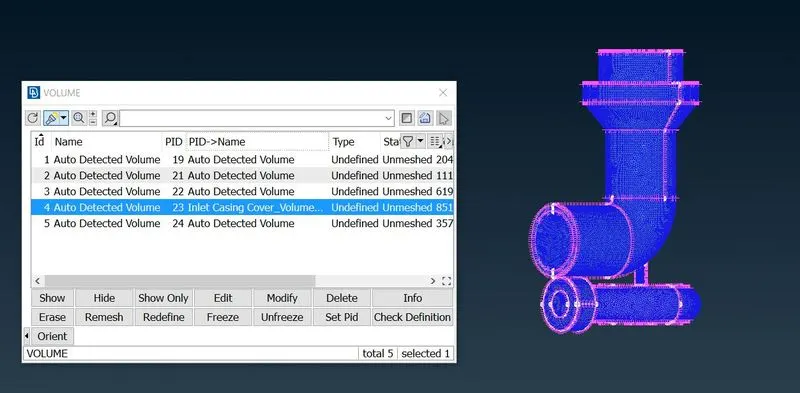
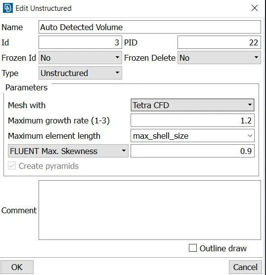
We then create the volumetric mesh, we choose the volume define option under volume mesh , where it checks for any intersection errors. then we get the dialoge box that shows the different volumes identified in the geometry , Some of the geometry are of external volume so we can delete those volumes. the we click on the specific entity and choose Tetra CFD mesh to be generated. then we click on the remesh option once we mention tetra CFD mesh for all the volumes. This generates the volume mesh in regions of fluid path or the regions where fluid comes in contact with the solid.
Finally to view the created volume mesh we create an intersection plane along the X-Y plane, tho have a cross-sectional view.
Surfece Mesh :
Volumetric Mesh :
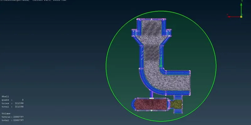
Conclusion :
Thus the geomentry is cleanedup using new tools like transform , TOPO and project. the surface mesh is generated using different mesh size for various components and the volume mesh is defined and the tetra volume mesh is thus generated.