Week 3 Challenge : CFD meshing on Turbocharger
Aim
Perform a topology cleanup on the given turbocharger model and generate a triangular surface mesh followed by a tetrahedral volume mesh based on the specified element sizings.
Learning Outcomes
- Performing topological cleanup on Geometries.
- Assigning appropriate PIDs to the various components.
- Generating surface mesh on the geometry.
- Generating volume mesh on the geometry.
- Performing checks on the geometry and mesh.
Procedure
The given turbocharger model was opened in ANSAv23 as shown below.
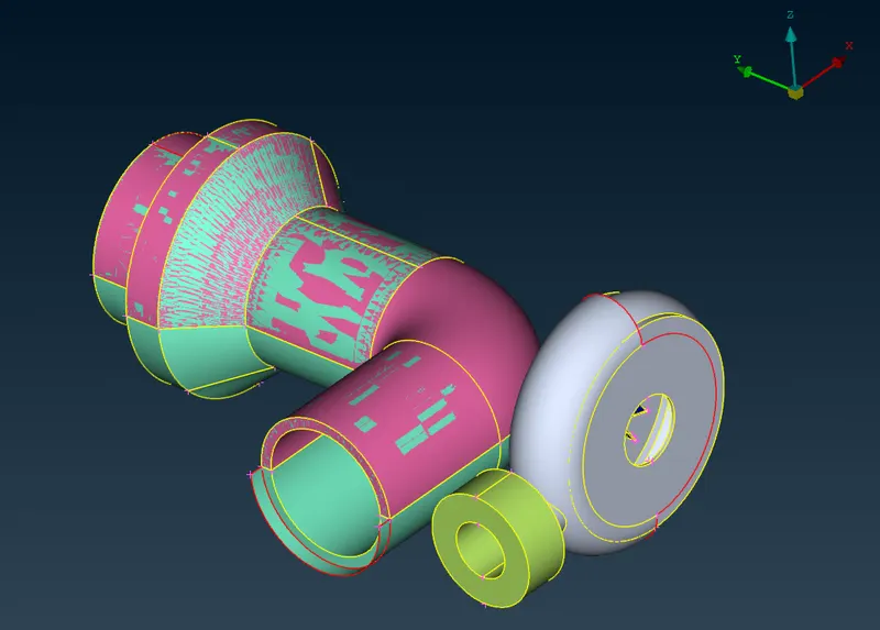
From the image, it is clear that there are multiple overlapping faces, holes and incomplete features in the model. A full topology cleanup is required prior to performing the surface mesh.
To start the topology cleanup, the overlapping faces marked with the pink-shaded PID are first selected and isolated as shown below.
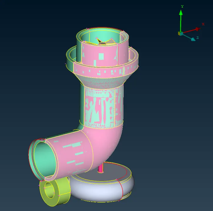
Isolating the geometry showed that there were no major features attached to this PID and hence this PID was deleted.
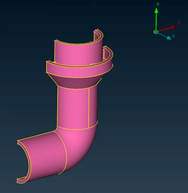
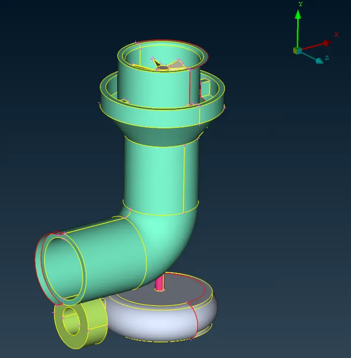
Upon deletion, the major overlapping of faces was resolved as seen below.
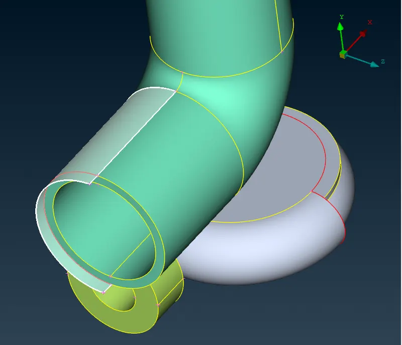
At the outlet of the compressor, a face was seen protruding out of the model. This face was deleted as shown below.
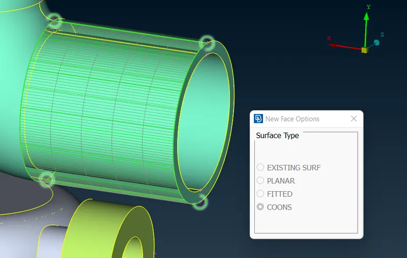
After the face was deleted, a new face was generated using the COONS method as shown below.
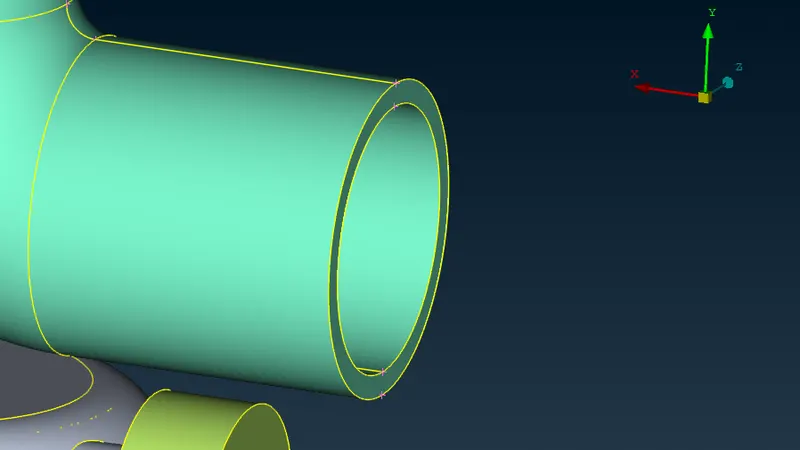
The final cleaned face can be seen in the image below.
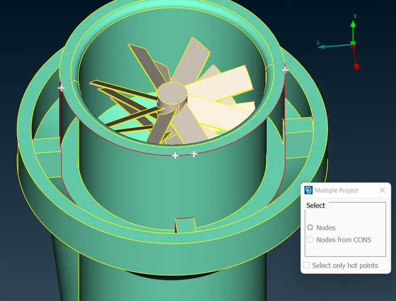
To construct the empty face near the compressor inlet, hotpoints were projected to the single CONS on top to ease the face generation.
Multiple faces were generated using the respective hotpoints as shown below to cover the empty face.
The multiple faces can be seen in the image below.
The modify tool was then used to remove the discretized faces and merge into a single face.
In order to fill the face in the turbo casing, hot points were generated on the Single CONS at intervals of 0.5 divisions as shown below.
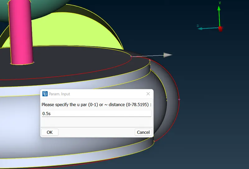
The hotpoints generated can be seen in the image below. The same process was conducted on the opposite side as well.
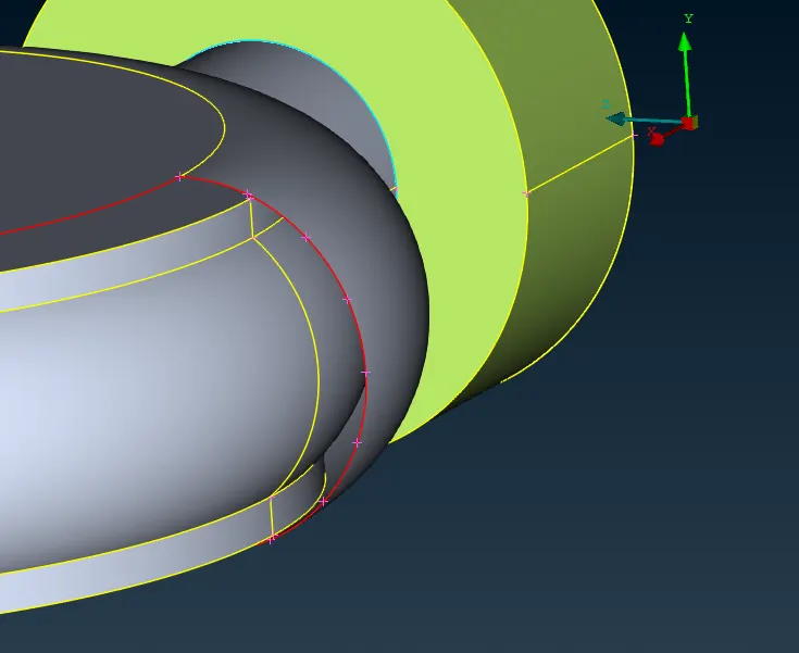
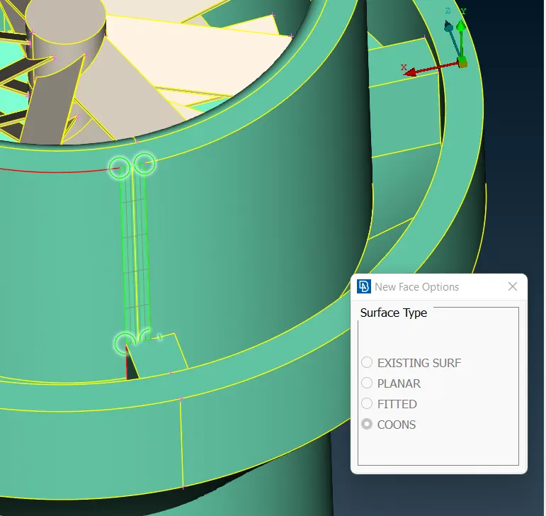
With the hotpoints on either side and the single CONS from the top, new faces were generated one after the other using the COONS method as shown below.
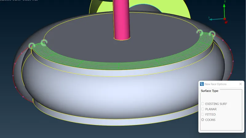
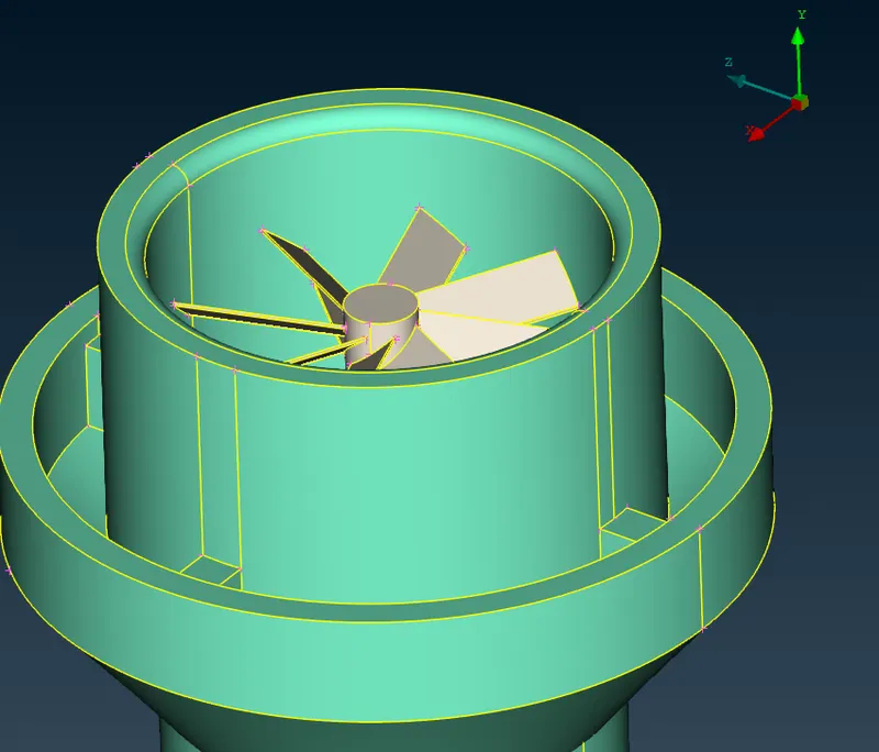
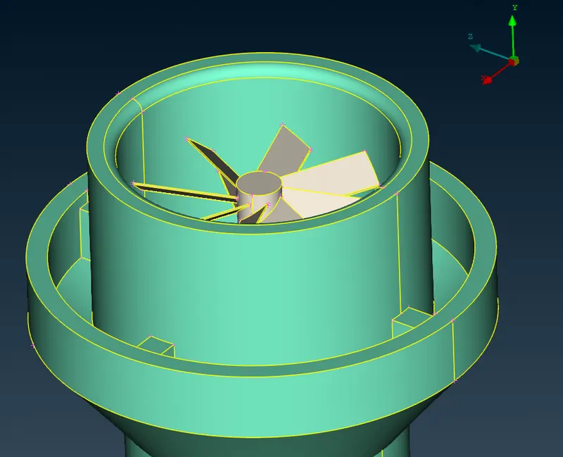
The final cleaned face of the turbo casing can be seen in the image below.
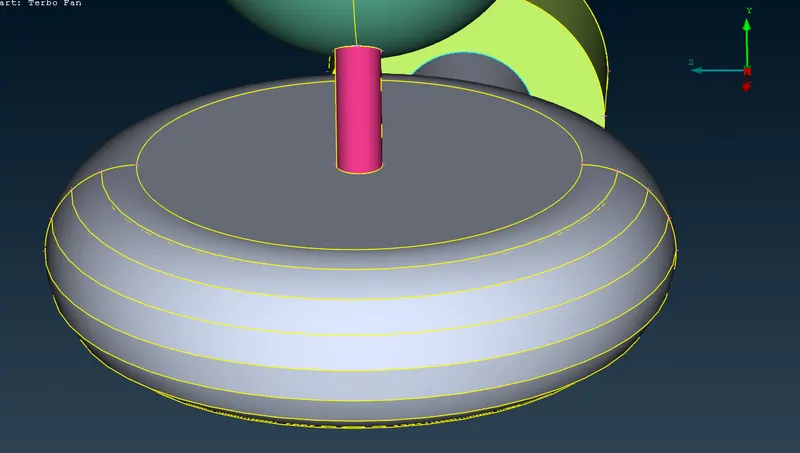
An intersection of faces was observed as seen in the image below.
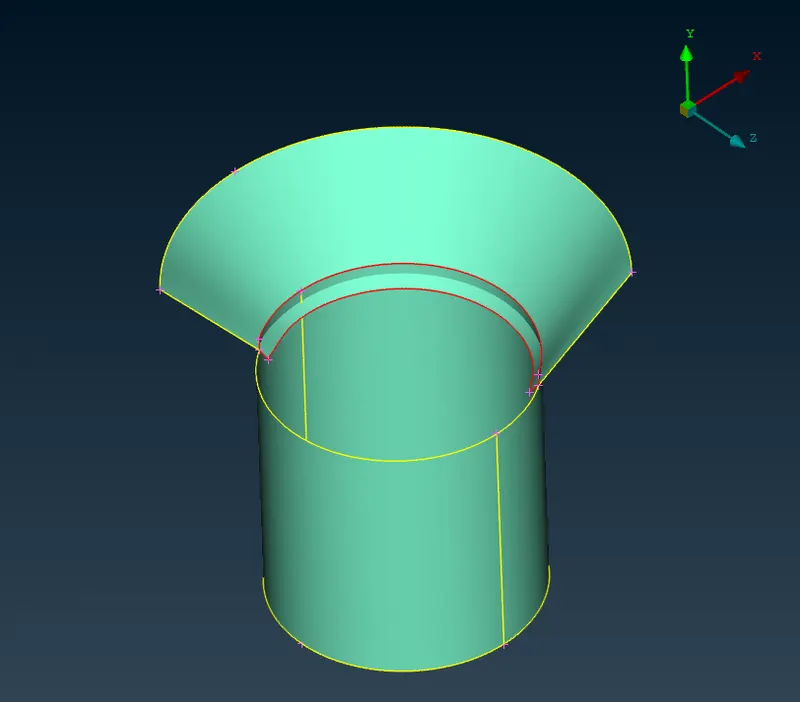
To fix this issue, the intersect tool was used and the respective faces were selected as shown below.
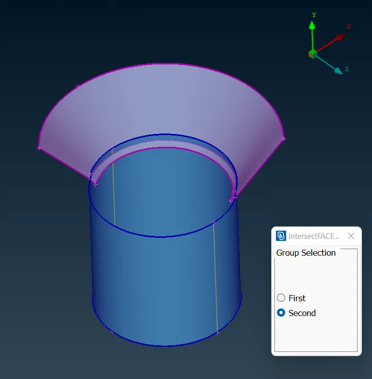
Once the intersect operation is complete, the remaining faces in the model were subsequently retained or deleted.
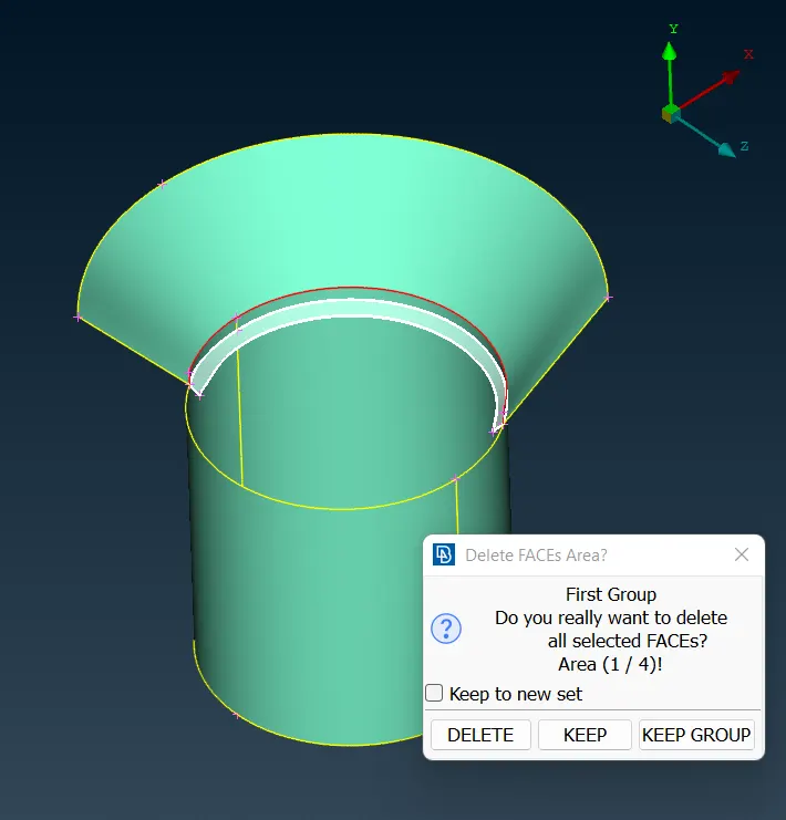
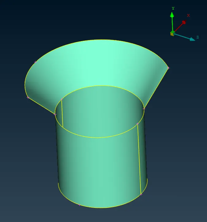
The cleaned faces after the intersection can be seen in the image below.
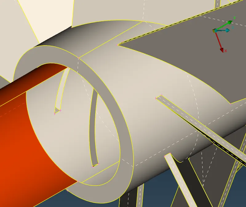
At the junctions of the blade stage and shaft, undesired faces were observed as seen below.
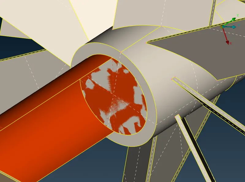
These faces were deleted as shown below.
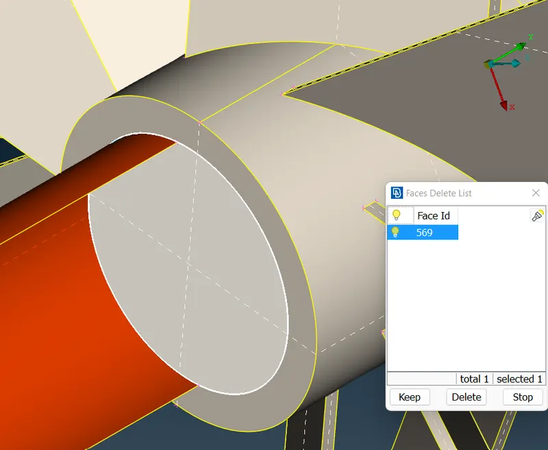
After the faces were deleted, the topo tool was used to connect the remaining single CONS and the final cleaned junction can be seen below.
An overlapping of faces was observed between the shaft and the blade stage as seen below.
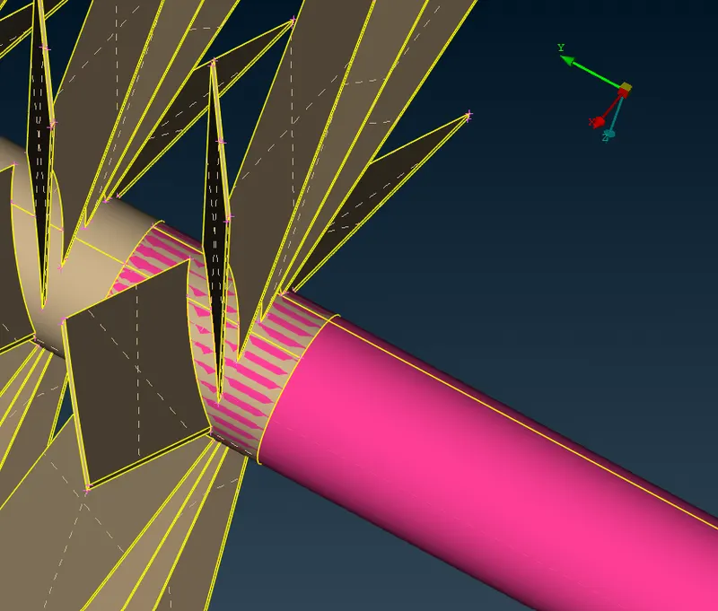
The project CONS tool was used to make the cut on the shaft. The faces inside the shaft region and overlapping faces on the blade stage were then deleted.
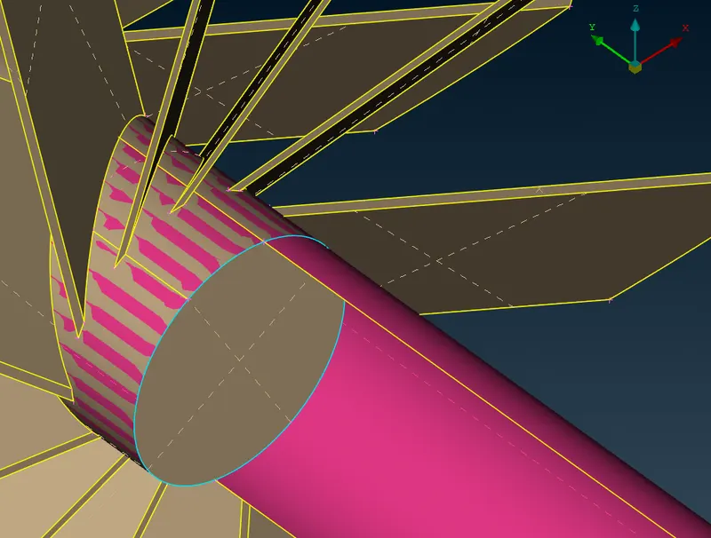
The final cleaned junction can be seen in the image below.
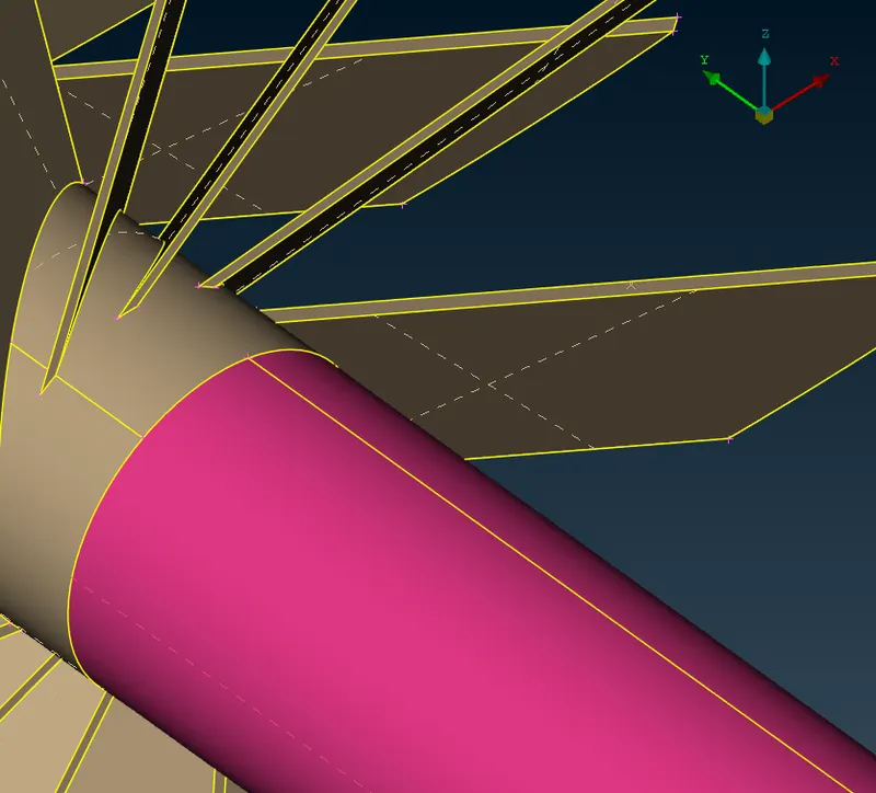
At the junction of the impeller and the shaft, an overlapping face was observed as shown below.
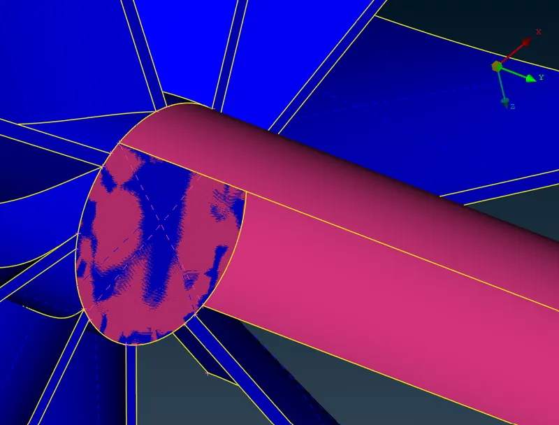
The overlapping face was deleted and the project CONS tool was used to project the cons on the shaft on to the impeller face. The final cut face of the impeller was then deleted. The topo tool was used to connect the remaining single CONS.
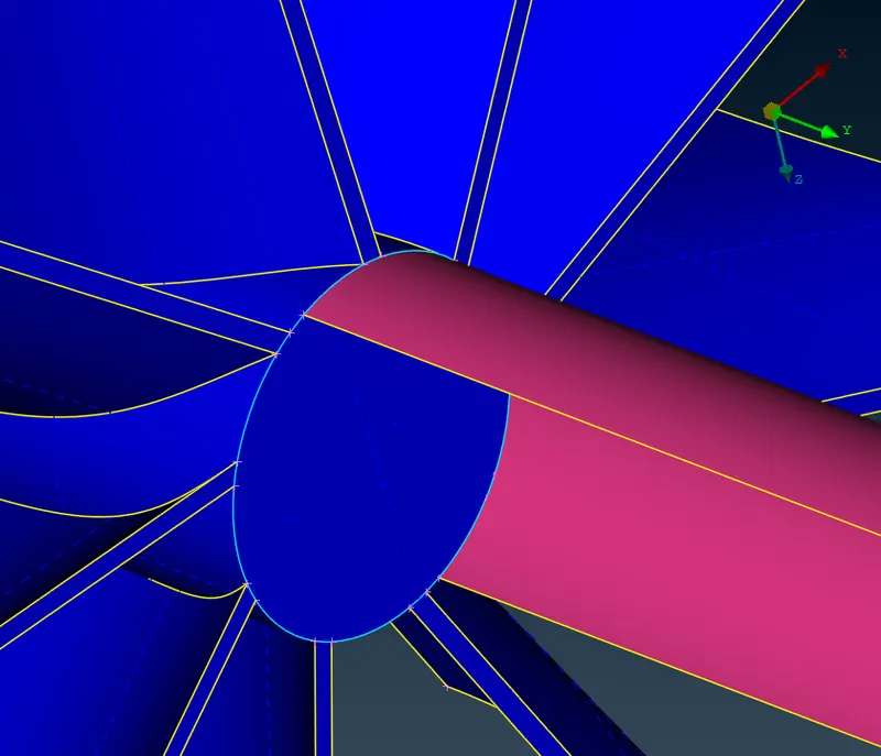
The final cleaned junction can be seen in the image below.
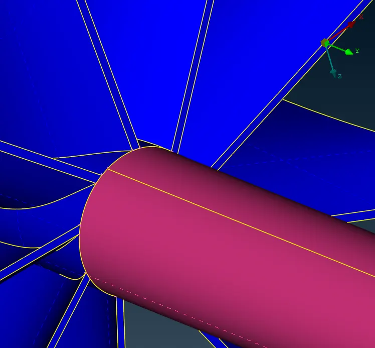
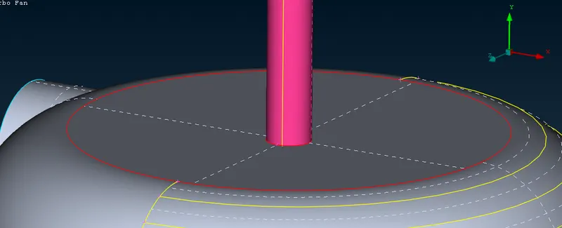
An open face was observed at the top of the turbo casing as shown in the image below.
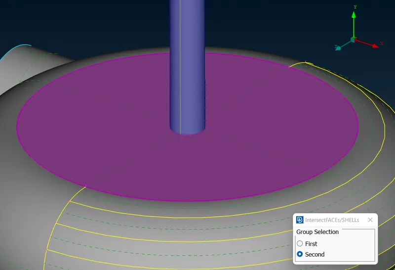
A new face was created and an intersection was observed with the shaft. The intersect tool was used to split the two components and delete the unused faces as shown below.
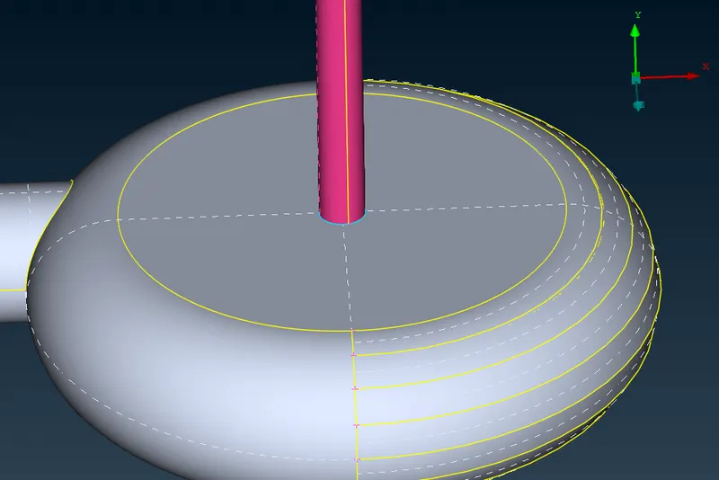
The final cleaned turbo casing can be seen in the image below.
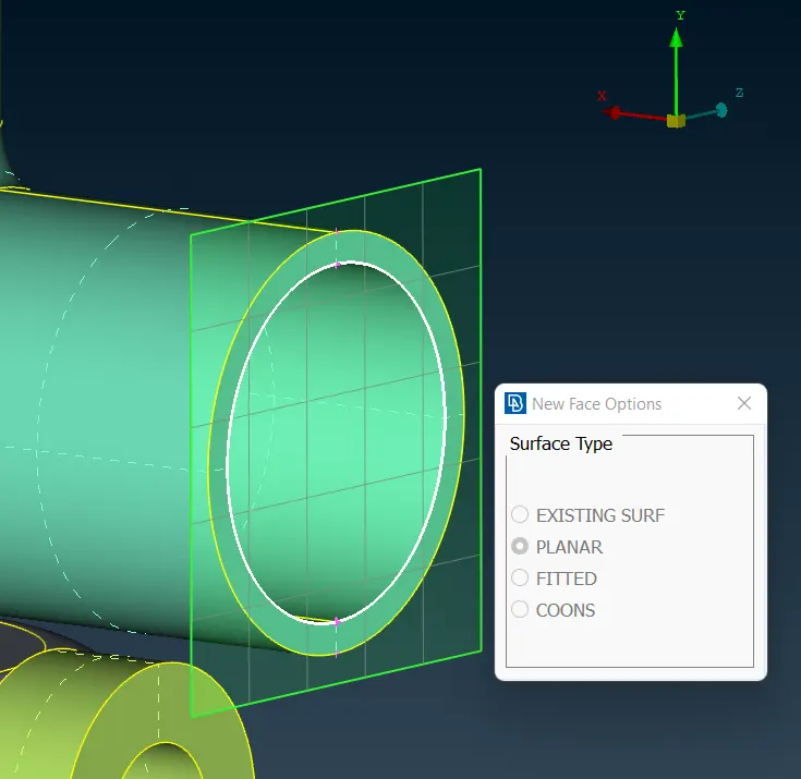
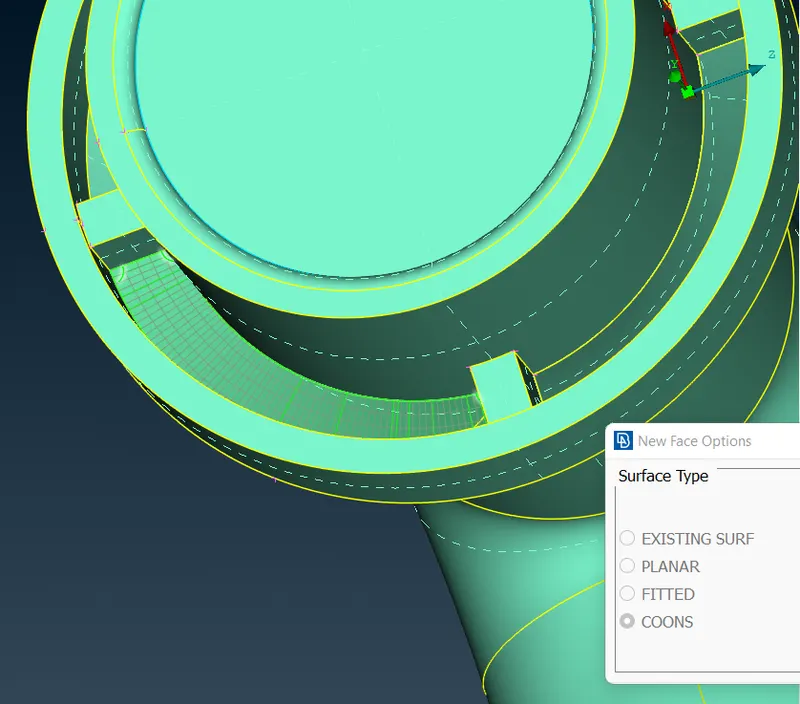
To complete the water tight geometry, all openings and vents were closed using new faces as shown in the images below.
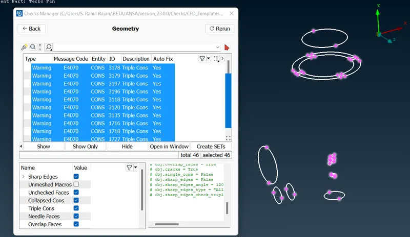
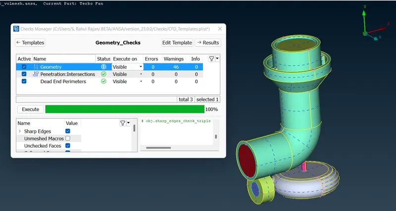
After the cleanup was complete, the geometry check was used to check for locations of triple CONS and single CONS if any. The image below shows the location of triple CONS in the geometry. These triple CONS are required for the simulation and hence retained for the meshing.
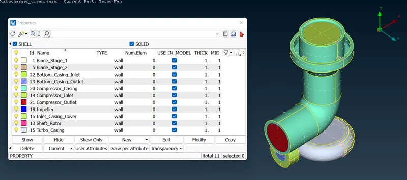
To complete the topology cleanup phase, the compress tool was used to delete the empty PIDs. PID names were then provided and assigned to the respective geometries as shown in the image below.
The surface mesh was created based on the sizings settings shown below:
- Blade stage-1 = 1 mm
- Blade stage-2 = 1 mm
- Impeller = 2 mm
- Shaft rotor = 1 mm
- Turbo casing = 5 mm
- Compressor casing = 5 mm
- Inlet casing cover = 5 mm
The edge sizings were updated on the model using the perimeter length tool on the respective PIDs. The surface mesh was then generated using the CFD mesh tool. Few of the regions on the surface however required additional care.
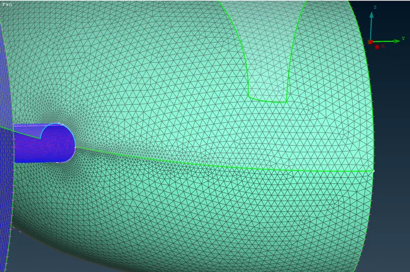
At the junction of the shaft and compressor casing, the mesh size varies from 1mm to 5mm. In order to obtain a good transition, the spacing tool was used to vary the mesh using a geometric progression as shown below.
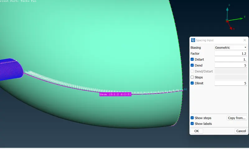
The resulting surface mesh seen below has a good transition while maintaining the respective sizing settings.
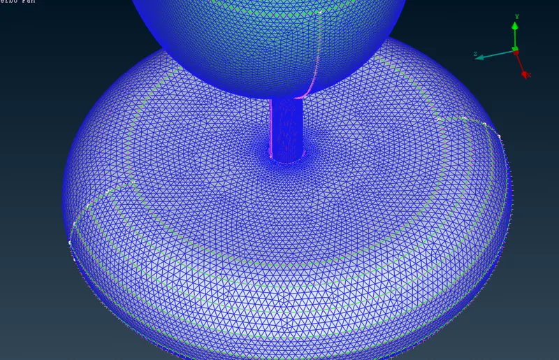
Similarly, the face on the junction of the turbo casing and shaft also had different mesh sizes of 1mm and 5mm. The sizing settings on the CFD mesh tool was updated to vary between 1mm and 5mm to create the mesh.
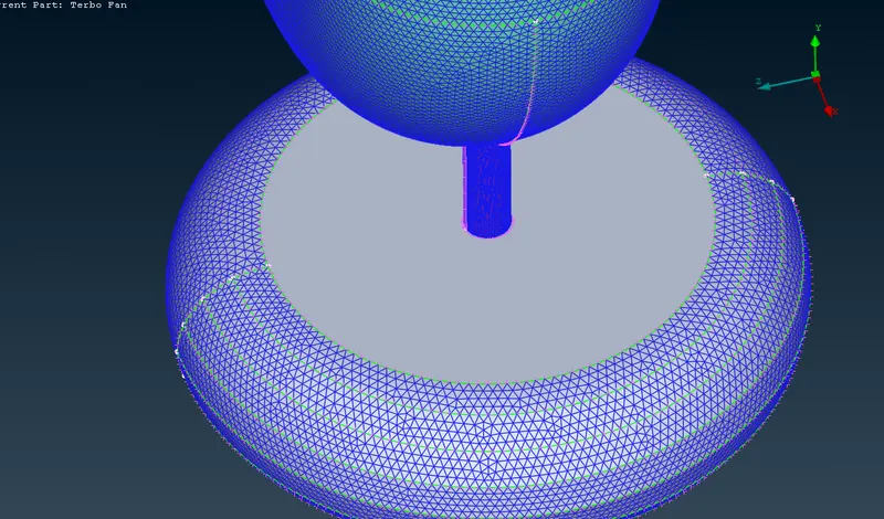
The resulting meshed face can be seen in the image below.
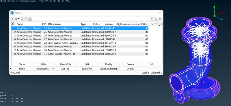
After completion of the surface mesh, the volumes to be meshed were listed and the volumes where fluid will pass through were retained and others were deleted.
The volume highlighted below corresponds to the fluid volume inside the compressor casing and hence this volume region was retained.
The image below shows the solid volume in the thickness of the compressor casing which is not required for a CFD analysis and hence deleted.
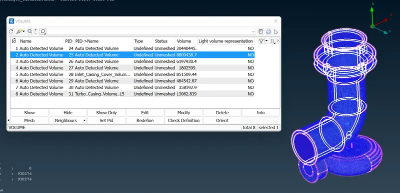
The volume highlighted below corresponds to the fluid volume inside the turbo casing and hence this volume region was retained.
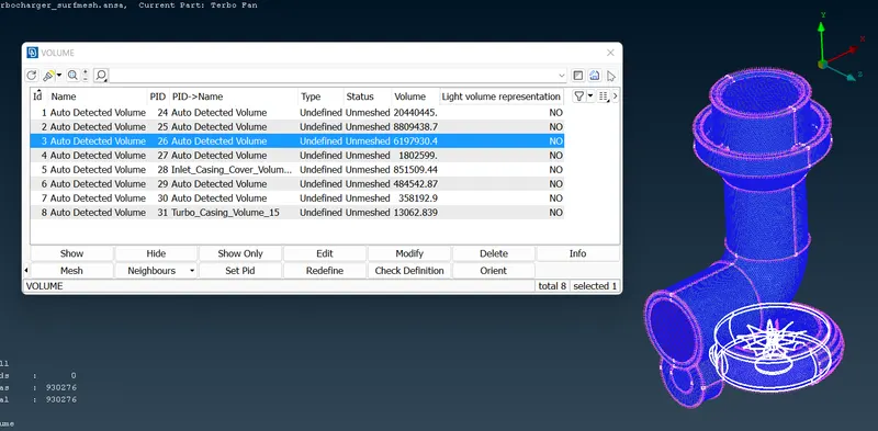
The image below shows the solid volume in the thickness of the turbo casing which is not required for a CFD analysis and hence deleted.
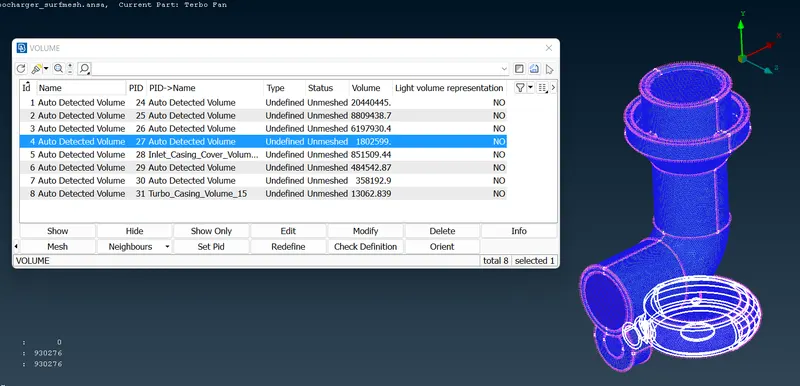
The image below shows the solid volume in the thickness of the inlet casing cover which is not required for a CFD analysis and hence deleted.
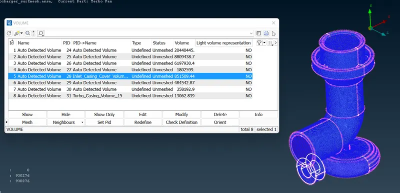
The image below shows the solid volume in the thickness of the Blade stages and the shaft which is not required for a CFD analysis and hence deleted.
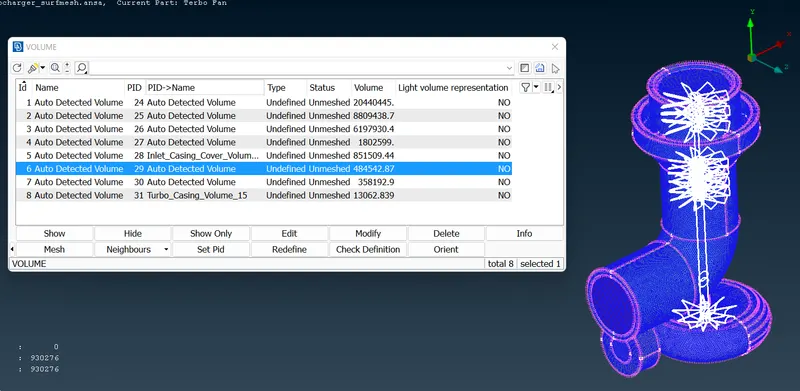
The volume highlighted below corresponds to the fluid volume inside the inlet casing cover and hence this volume region was retained.
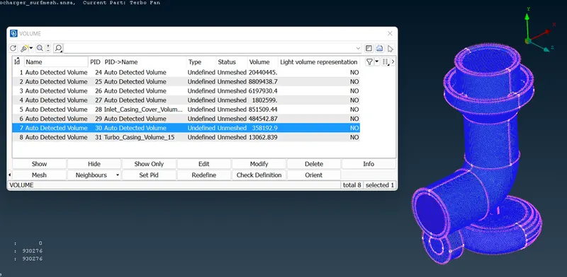
The volume highlighted below corresponds to the fluid volume inside the turbo casing and the inlet cover and hence this volume region was retained.
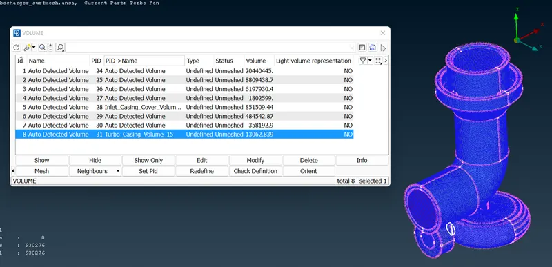
Once all the fluid volumes were isolated, a tetrahedral volume mesh was then generated on the various fluid volumes. The sizings of the volume mesh were automatically determined from the sizings on the surface mesh and hence additional size settings were not required for the volume meshing.
Results
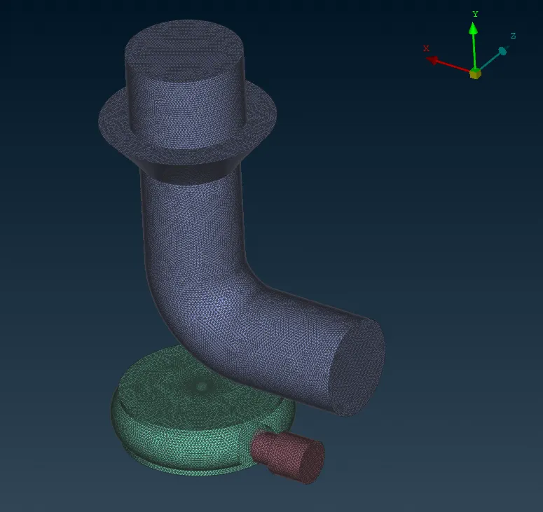
The final surface mesh on the turbocharger geometry can be seen below. The total cell count of the surface mesh is 930276cells.
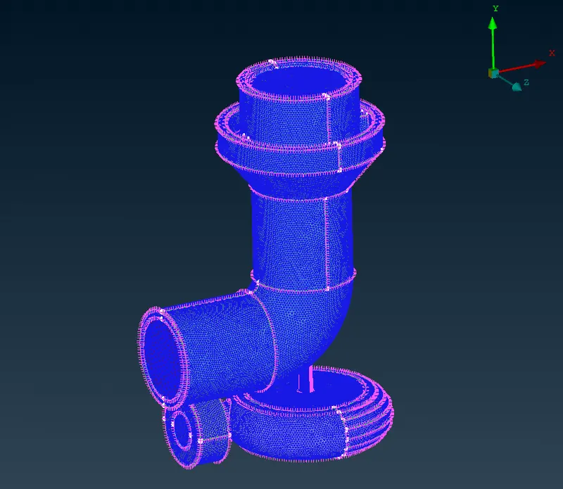
The surface mesh on the individual components can be seen below.
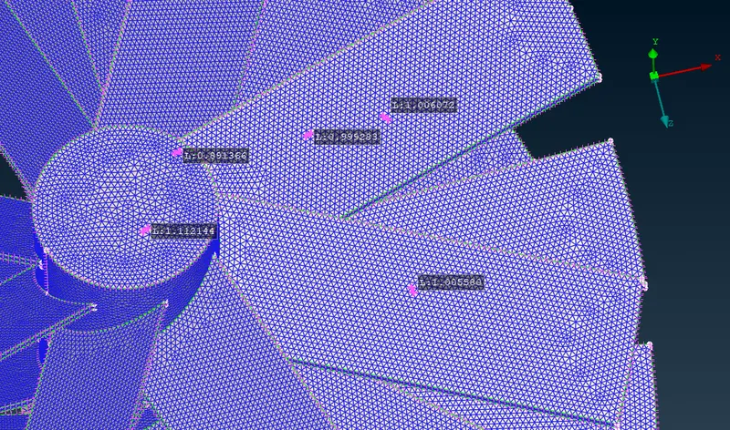
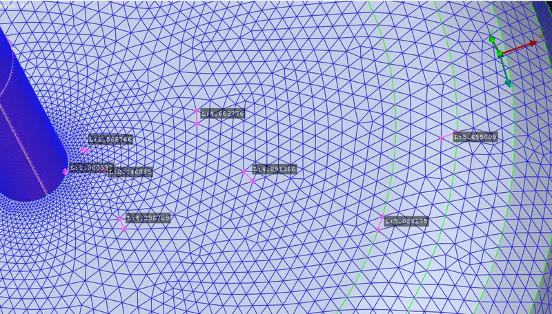
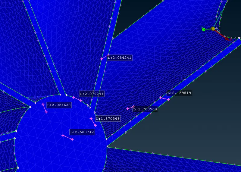
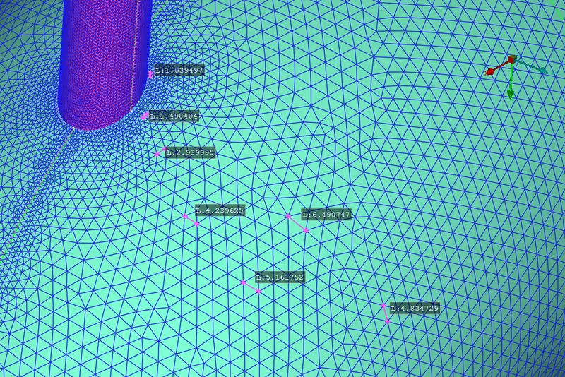
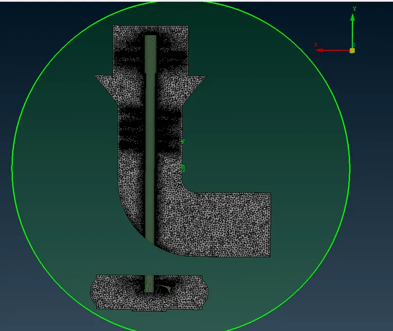
The final volume mesh on the turbocharger consists of 7119082 tetrahedral cells as shown below.
A cross-sectional view of the volume mesh can be seen in the image below.
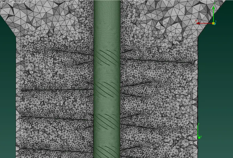
The image below shows a close-up view near the blade stage of the turbocharger. A good transition can be seen in the volume mesh between the fine and coarse mesh regions.
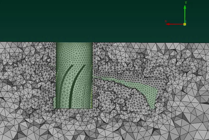
The image below shows a close-up view near the impeller of the turbocharger. Similar to the above image, a good transition can be seen in the volume mesh between the fine and coarse mesh regions here as well.
With the volume mesh completed, final checks were conducted to verify the mesh and the results can be seen in the images below.
Geometric check:
The results of the geometry check showed no errors. Warnings were shown for the presence of triple CONS, since they are at desired locations for the simulation they were retained.
Surface Mesh Check:
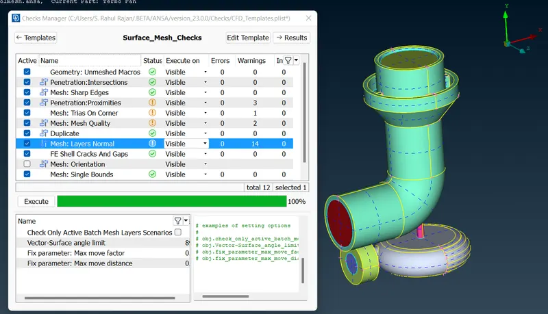
The results of the surface mesh check showed no errors. Warnings were shown for the poor proximity capture and presence of mesh elements of poor quality. These warnings may be fixed using additional refinements or surface mesh improvements on the respective regions. They contribute to a very small part of the surface mesh and hence may be ignored to maintain computational costs.
Volume Mesh Check:
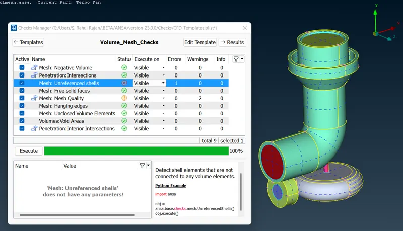
The results of the volume mesh check show only 1 error which is the presence of unreferenced shells. This error corresponds to the outer solid casing of the geometry not being in touch with any of the volume regions. This error may be ignored for the purposes of a CFD analysis as only the fluid volumes will be exported for simulation. Similar to the surface mesh check, the volume mesh check has also identified cells with poor mesh quality. These cells may be refined or improved by altering the geometry to fix this issue. The decision to refine the mesh or improvise the geometry can be taken based on the allocated computational budget and/or desired fidelity of the problem.
The drive link to the ANSA file is attached below:
https://drive.google.com/file/d/10kIptZ9goK7U2LCScPy92Czd9IhaQdVE/view?usp=sharing
Conclusion
A topological cleanup was performed on the given turbocharger model where multiple faces were generated and reconstructed to create a water-tight geometry. PIDS were assigned to the various components of the turbocharger to aid ease of meshing and simulation. A surface mesh followed by a volume mesh was then generated on the model using the specified settings which encompassed all the fluid regions in the turbocharger. Finally, geometry, surface mesh and volume mesh checks were conducted to verify the final geometry and mesh. The resulting mesh was able to capture the curvature and other fine details of the geometry well. Few cells with lower mesh quality were observed, these cells may be fixed either by further refinement or mesh improvements which may cause geometric modifications.