Week 3 Challenge : CFD meshing on Turbocharger
CFD meshing on Turbocharger
AIM :-
For the given model, check for the geometrical errors to make appropriate volumes. Create and assign PIDs as shown in the video. Perform surface mesh with the given target lengths as per PIDs
- Blade stage-1 = 1 mm
- Blade stage-2 = 1 mm
- Impeller = 2 mm
- Shaft rotor = 1 mm
- Turbo casing = 5 mm
- Compressor casing = 5 mm
- Inlet casing cover = 5 mm
Learning Outcomes
- Geometry cleanup
- Surface meshing
- Volume meshing
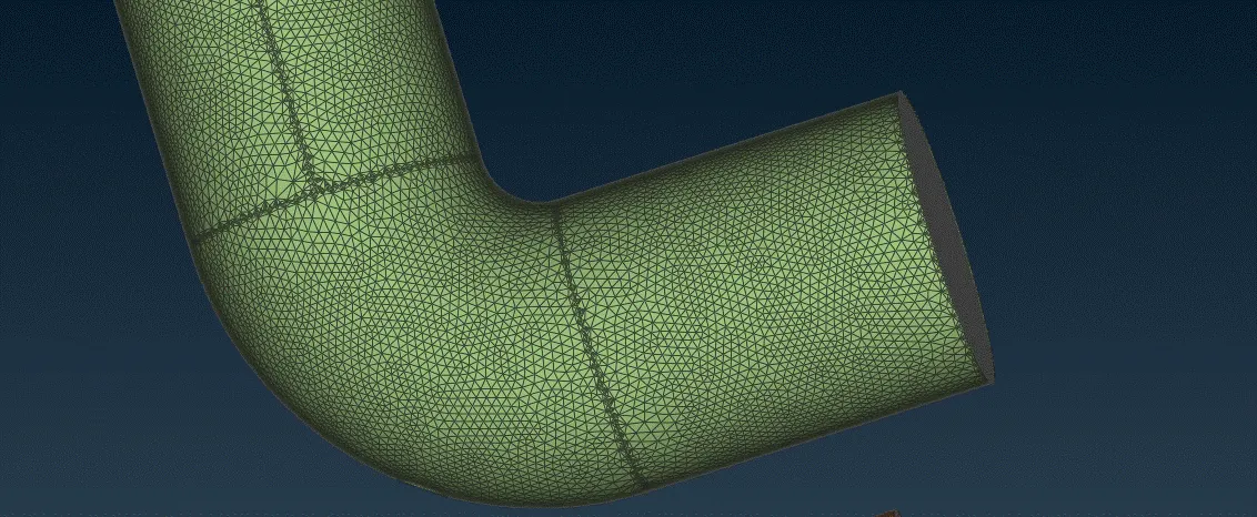
Surface Meshing :-
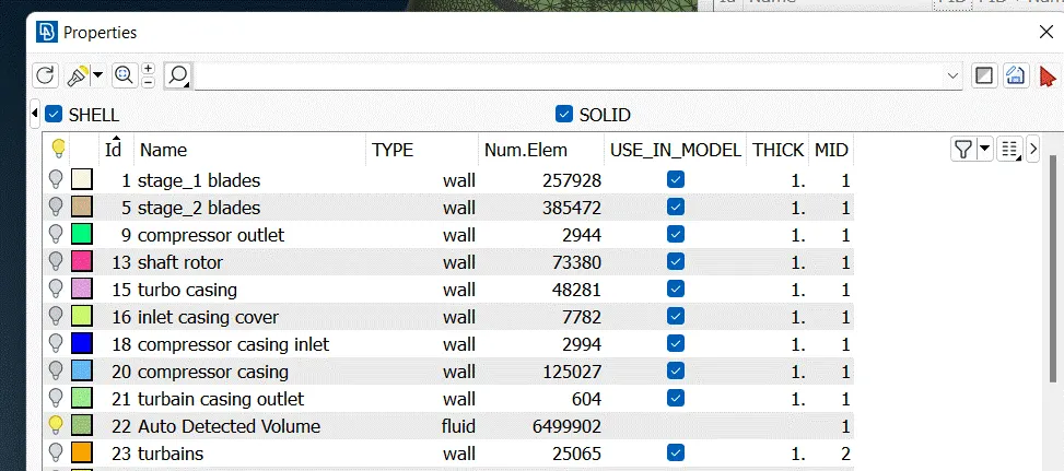
PID'S:-
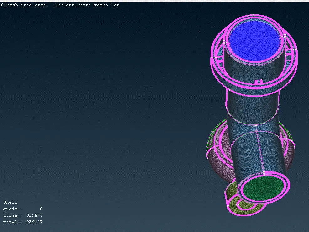
Meshing 5MM Grid :-
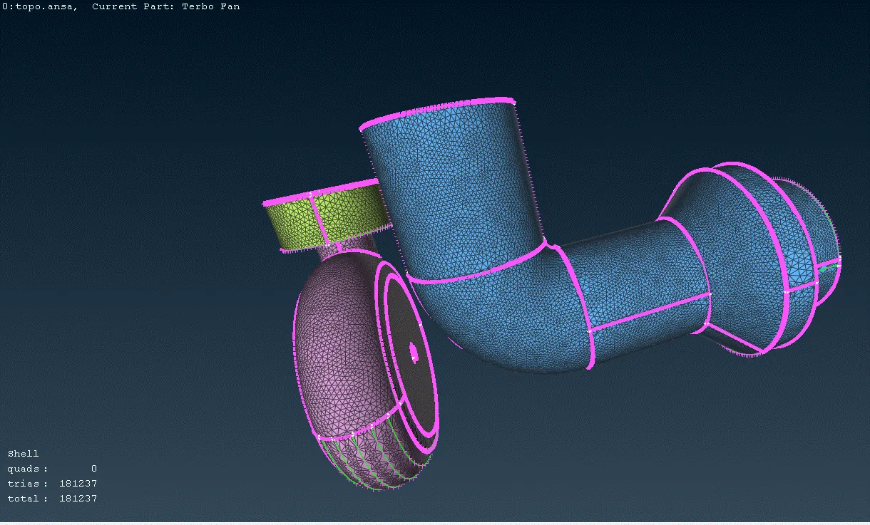
Meshing 2MM Grid :-
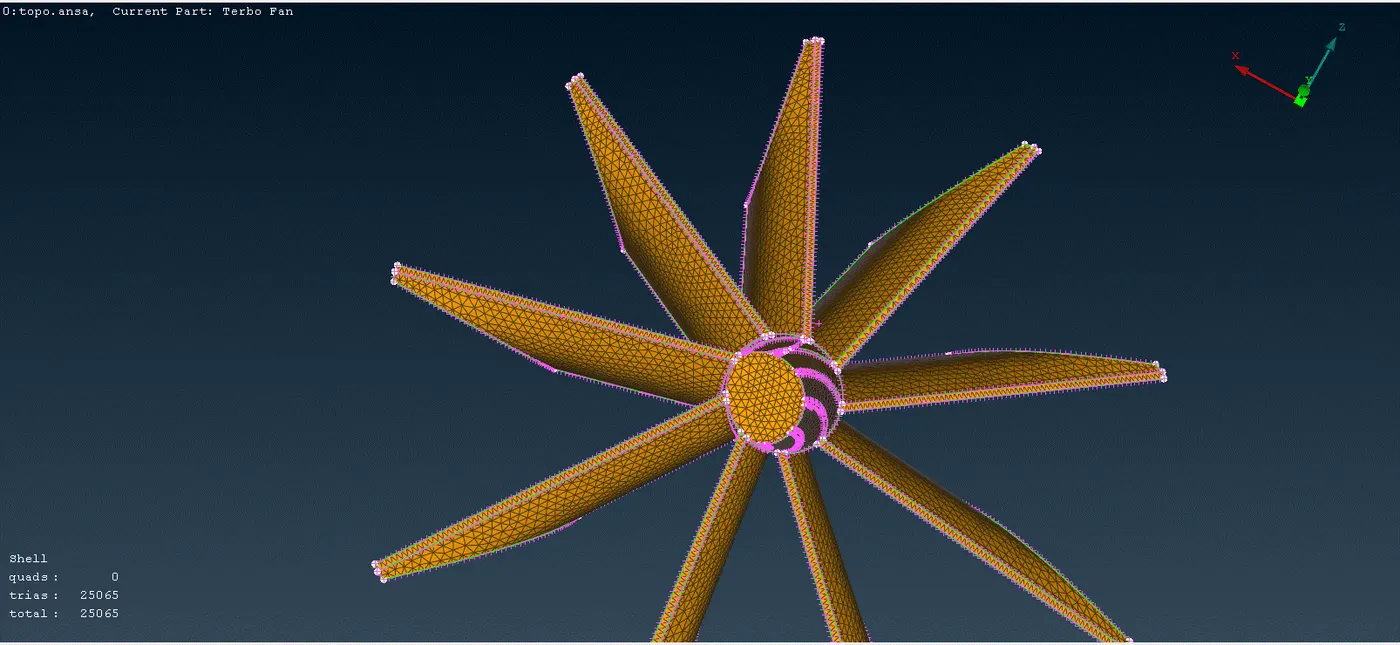
Meshing 1MM Grid :-
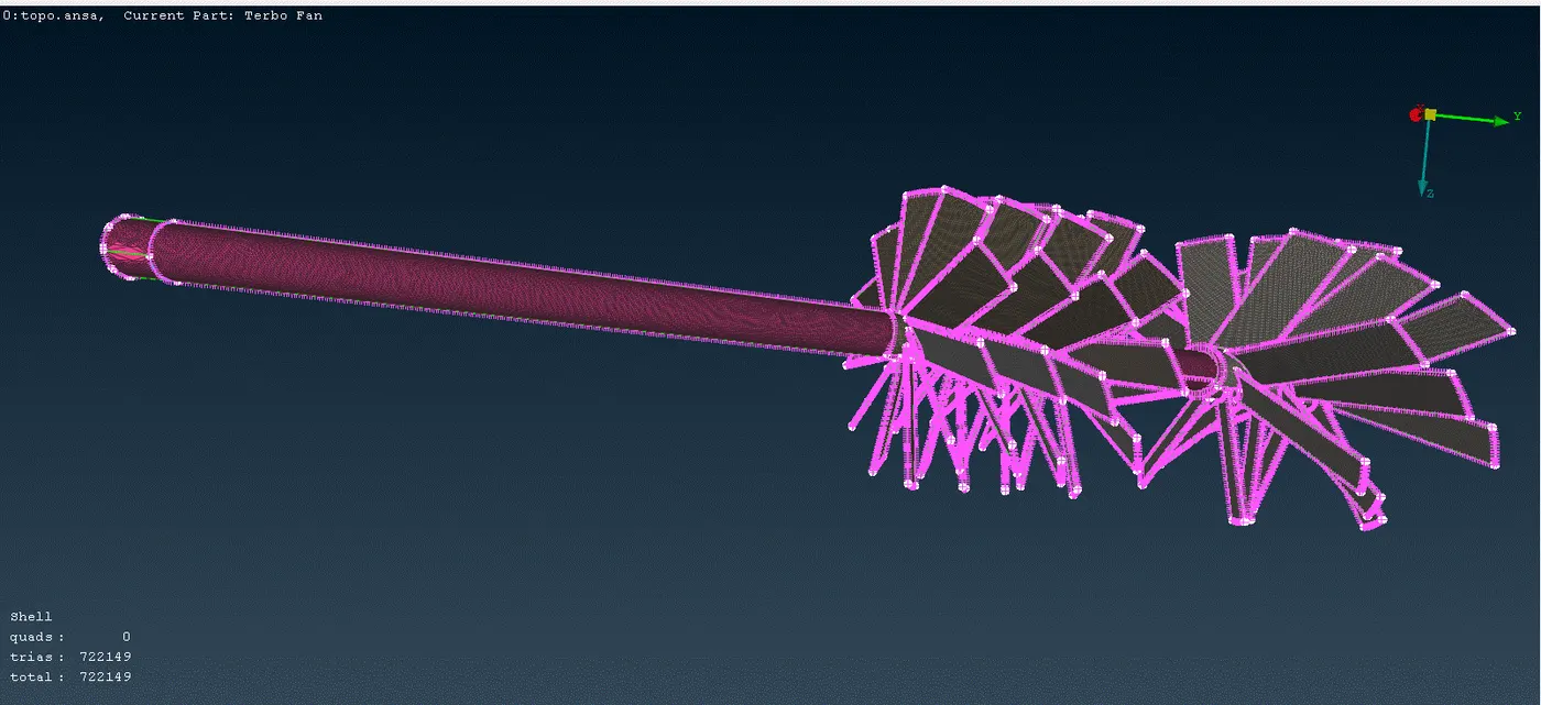
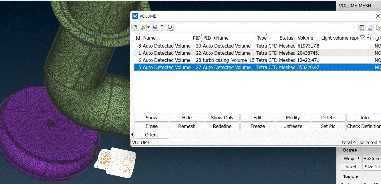
Volume Meshing :-
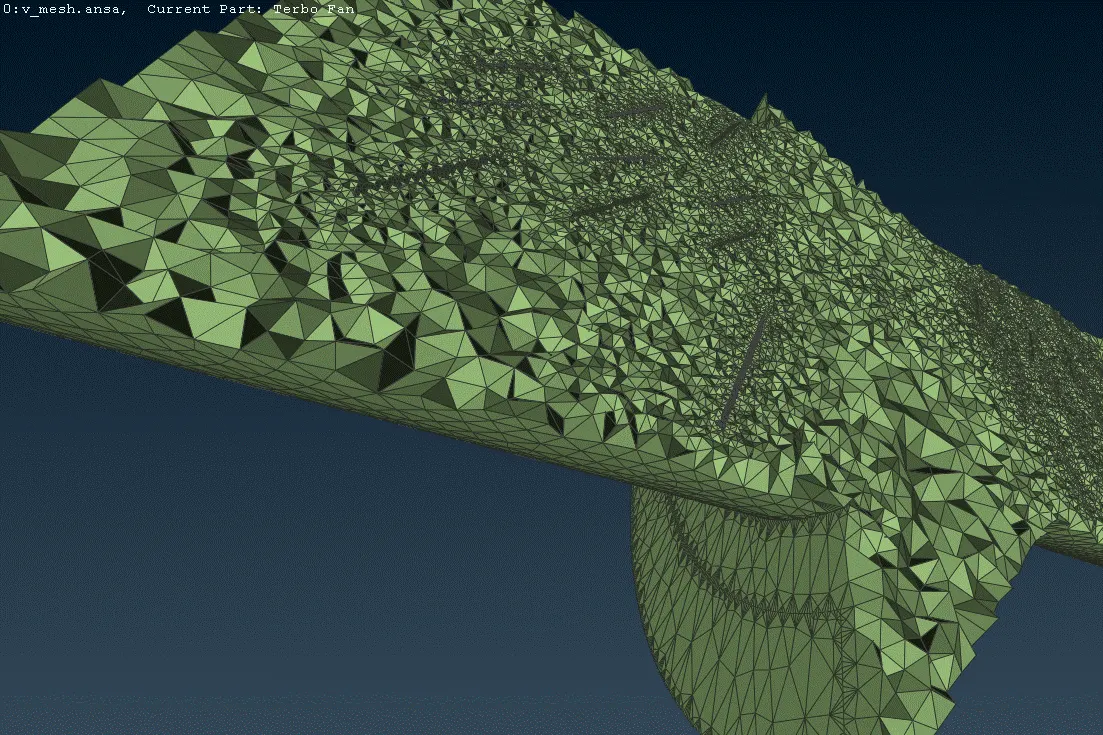
v_mesh :-
A mesh divides a geometry into many elements. These are used by the CFD solver to construct control volumes. Terminology: • Cell = control volume into which domain is broken up.
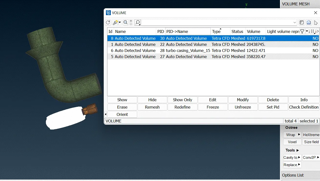
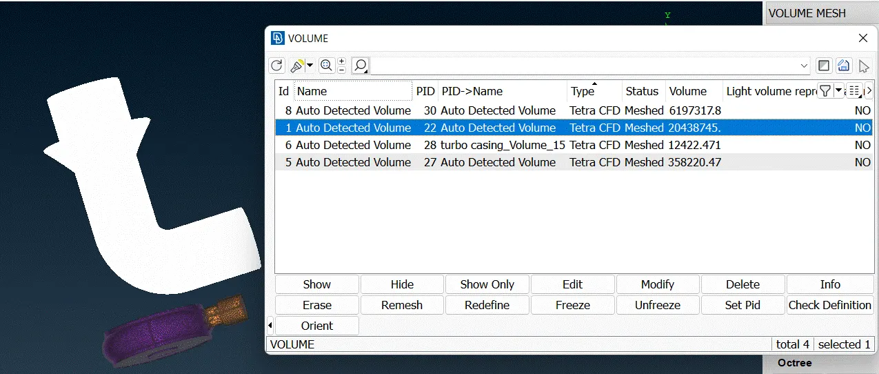
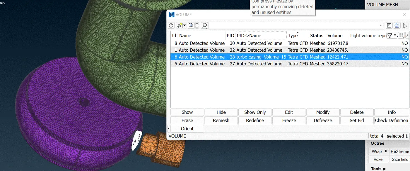
https://drive.google.com/file/d/111BJRuwW9sGaQEgL7RsOHubz6CaYZI6q/view?usp=sharing
https://drive.google.com/file/d/1i7HUzI2TUG-6tZu2jb2Z-6LbiwzqLiOZ/view?usp=sharing
https://drive.google.com/file/d/1GasRJt-XWYMwp5znWQBX9jVYz014dBaN/view?usp=sharing