Week 3 Challenge : CFD meshing on Turbocharger
- For the given model, check for the geometrical errors to make appropriate volumes. Create and assign PIDs as shown in the video. Perform surface mesh with the given target lengths as per PIDs.
- Blade stage-1 = 1 mm
- Blade stage-2 = 1 mm
- Impeller = 2 mm
- Shaft rotor = 1 mm
- Turbo casing = 5 mm
- Compressor casing = 5 mm
- Inlet casing cover = 5 mm
In this challange we have done a geometry cleaning and surface meshing with different target length we followed following steps
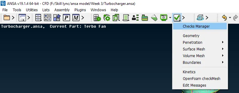
- Geometry Check - We have to the taskbar under a file and there we have to find the check button as shown in image.
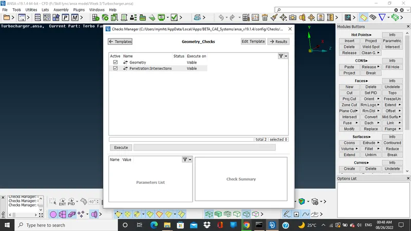
- So when we click new window open where we have to select the geometry check. Then we have to execute the geometry check.
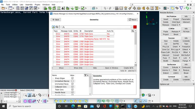
- When we click on execute then it show the error present in geometry. Then we have to perfom the geometry clean up to clear all the error.
- Removing a overlapping surface - So when we open a model and switch to the pid mode it showing the two surface one in the green and other in the pink, So we have to remove the pink surface. By the following steps.
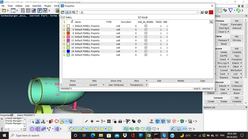
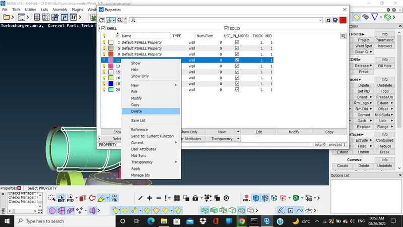
- So when we go to properties there we can see the multiple properties are created we have to delete one property from this so we an remove a pink surface. Here in the image attached below we can see the property no. 11 denotes to pink surface so we simplly delete it by. Right Click>Delete>Ok
- Deleting extra surface and creating the new surface as required - So when we see the gemotery in the image given below there is a extra surface at the turbo casing
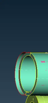
- Here we can use project option under cons then select the hot points and then press enter select the surface on which we have to project then after that surface get seperated. Then use delete option under the faces option press enter.
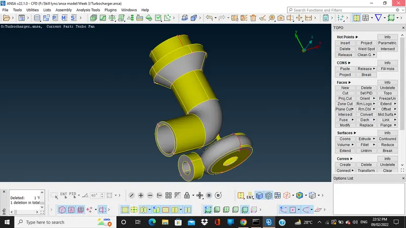
- In gemotery there are various red line so that is because of missing surafce so we have to create a new surface for that we have to go to new option under faces.
- Then we have to select the red lines to make a new surface go to coons press enter if the surface is not smooth then choose the alt option to change it and make a smooth looking surface. This for turbocasing.
- For the Impeller casing we hava to use transform go to the copy the select the surface which we have to copy on the other side. When we press enter key it will ask for the coordinates so we have to insert the hotpoints we required three hot points two points are present in geometry and we have to insert on either side.
- Select the three hot points to give a coordinates then press enter and the new surface is created
- There is a hole in the new surface so we have to use a fill hole option to fill that hole.
- Then again switch to pid mode and hide all the casing we have view some more overlapping surface so we can delete all the overlapping surface from the shaft and the impeller.
- After when we view the fan blade there are to many faces select and delete all the extra faces. Use the topo option to get rid of the red lines.
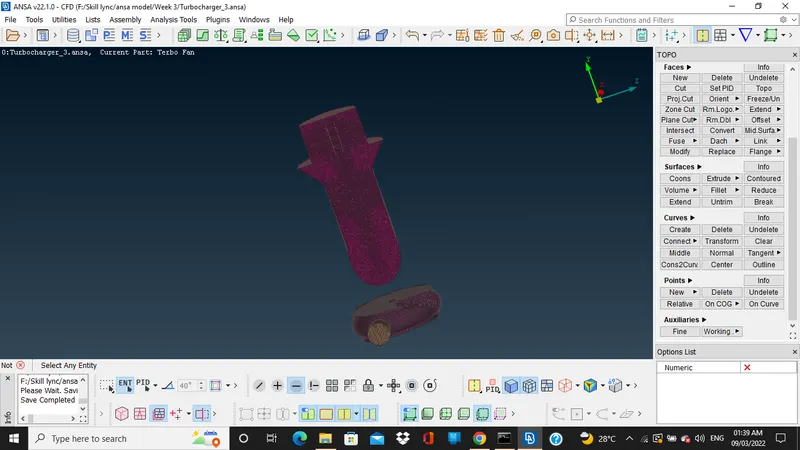
- Performing a mesh - Switch to Mesh mode give the perimeters for the each pid then go to the spot mesh option and select the pid then press enter.
- Volumetric Mesh - For the volumetric mesh we have to go under the volume tab then click on define the list of pid are there.
- Choose the pid surface where the fluid flow is present and delete the rest from the list.
- Then press right click on the remaining select remesh option the put it on tetra cfd apply.
- Reference
https://drive.google.com/drive/folders/1HggiUOGKjKi8ZE1-KAjYgDpQUsrrtZH3?usp=sharing