Week 3 Challenge : CFD meshing on Turbocharger
AIM: For the given model, check for the geometrical errors to make appropriate volumes. Create and assign PIDs as shown in the video. Perform surface mesh with the given target lengths as per PIDs.
- Blade stage-1 = 1 mm
- Blade stage-2 = 1 mm
- Impeller = 2 mm
- Shaft rotor = 1 mm
- Turbo casing = 5 mm
- Compressor casing = 5 mm
- Inlet casing cover = 5 mm
INTRODUCTION:
A turbocharger is a turbine driven forced induction device that is used to increase the efficiency and power output of an internal combustion engine. This is accomplished by forcing additional compressed air into the combustion chamber with the assistance of exhaust from the engine. In common usage, the term "turbo" is used to refer to this type of device.
ANSA:
The automotive industry makes extensive use of the computer-aided engineering tool known as ANSA for finite element analysis and computational fluid dynamics (CFD) analysis. BETA CAE Systems is the company that created it. A number of BETA CAE Systems subsidiaries and business agents work together to disseminate the software all over the world.
ANSA ensures that the connection between the CAD geometry and the FE mesh remains intact. This indicates that the FE meshes are superior representations of the geometric parents to which they belong. Additionally, it is simple to maintain and update any changes in the geometry by merely reworking the updated area rather than starting from scratch to recreate the FE. This makes it easy to do so.
It includes several proprietary algorithms for meshing that are appropriate for computational fluid dynamics (CFD) models as well as structural models. Automatic net generation for structural analysis was the original meaning of the acronym ANSA, but the software has rapidly expanded beyond that scope. TOPO MESH, VMESH, DECK-SOLVER, MORPH, and HBLOCK are the names of the various activities that can be accomplished with the help of ANSA's broadly six menus.
ANSA contains many different kinds of modules, including:
- A collection of tools for tidying up geometry and configuring PIDs is referred to as TOPO.
- MESH refers to a collection of tools that can generate Surface Mesh or 2D Mesh.
- To generate a solid or three-dimensional mesh using volume mesh.
- SOLVER DECKS are tools that are built on various solvers, such as ABAQUS, RADIOSS, and ANSYS, amongst others.
- MORPH is an advanced tool that captures geometry with greater precision during the meshing process.
Method of solving the problem (In order to solve the problem, we will follow the procedure below,) :
- Import the model created in CAD.
- Cleanup of topography and geometry.
- A check on your geometry.
- The configuration of any necessary PIDs
- Determining the size or length of the element.
- Optional selection of the type of Mesh.
- In the CAD model, we are generating the surface mesh.
- Generating a volumetric mesh for use.
1) Importing of CAD model :
- In order to import the CAD model, please follow the instructions below.
Navigate to the file menu, select open, then browse to the location of the CAD model, select it, and then click open.
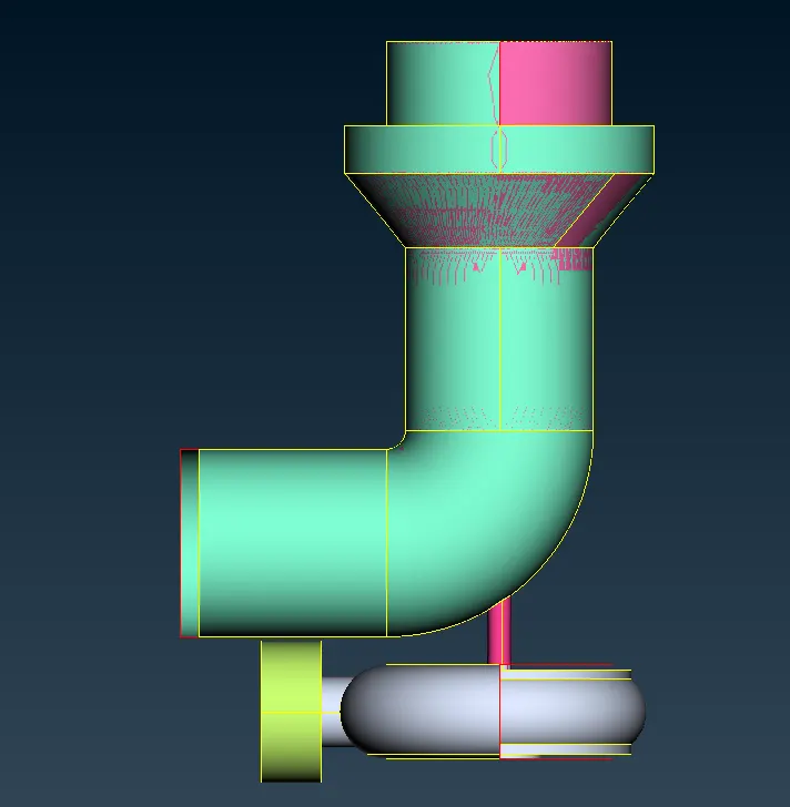
When you open the model for the first time, you will notice some errors, such as glitching in the model, intersections, and single cons, among other things. Let's go through each topo error and fix it one at a time.
2) Correcting any topological mistakes:
a) Eliminating any existing glitches:
You can see an error in the model in the figure that was just provided; this occurs whenever there is a surface underneath it. It was a mistake in the design. You can see it in the image that we've provided below When the extra surface beneath it is removed, you will notice that the glitching has stopped occurring.
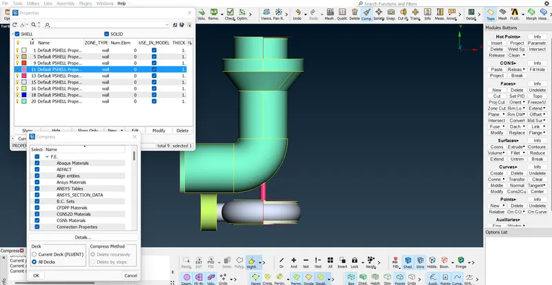
In the above image, we have to follow the same steps to delete the unwanted surface of pink PID, creating an error by using COMPRESSING option
- When you look at the figure below, you will notice that there is no glitch like the one that can be seen in the earlier image when the pink surface is removed.
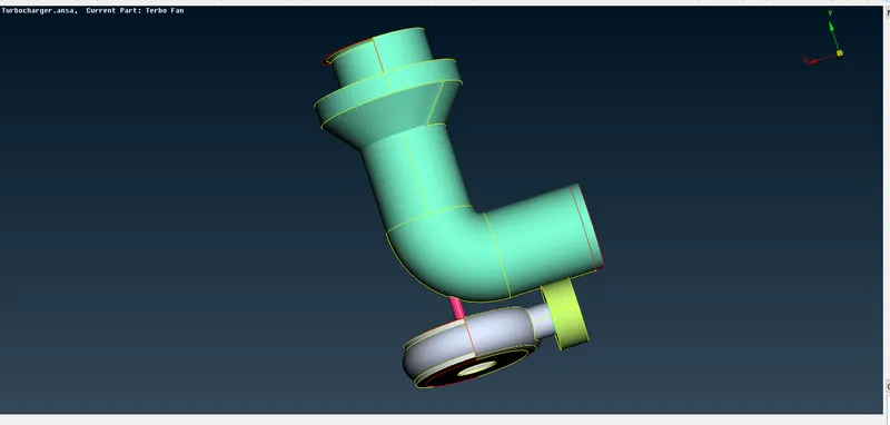
After cleaning up the glitches in the preceding figure, you will notice a number of errors, including open surfaces, intersection errors, and so on. Let's go through each of the topo errors one at a time and fix them.
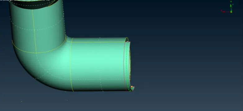
b) Eliminating the extended surface at the outlet of the compressor casing:
You will notice that there is an additional extended surface present at the compressor casing outlet, as shown in the figure that is located above. In order to divide the extra surface, you can use the project tool to project the lower con onto the upper surface.
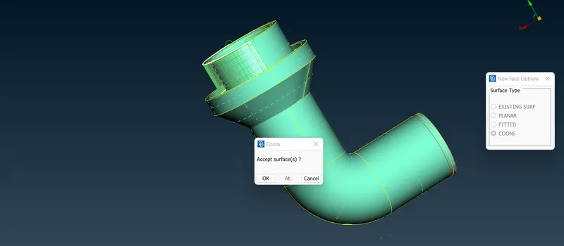
c) Establishing a new surface at the inlet of the compressor casing:
You will notice an open surface with a single con when you are looking at the inlet of the compressor casing. We create a new surface by making use of the fitted options found under the New heading (under faces). Another method of patching involves the creation of hot points and the formation of small, small surfaces.
d) Developing a new surface on the turbine housing:
The open surface for the turbo casing is the subsequent topo error. You can see the open surface of the turbo casing in the image that's been provided below.
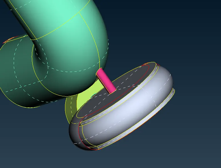
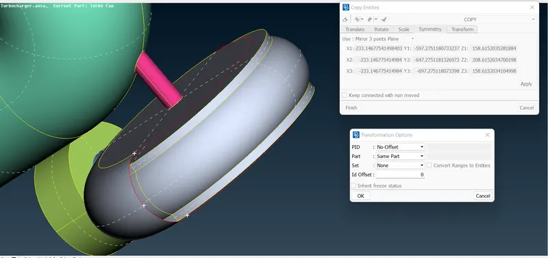
This can be cover in a single go by using TRANSFORM OPTION.
MENUBAR>Utilities>Transform (COPY)
- This function can be used to translate, rotate, transform, scale, symmetry, or mirror selected entities. It can also symmetry selected entities (Faces, Points, Elements etc). The entities that were selected are duplicated in their new location.
e) Integrating the blades and the shaft rotor into a single volume:
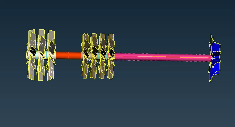
You can see a lot of triple cons in the image below; this is because there are surfaces in between each and every blade. If there were no surfaces, there would be no triple cons.
It is imperative that all of those unnecessary surfaces be eliminated, and that any triple cons be reduced to double cons. In order to have the entire blade along with the shaft in one volume.
3) Verifying the absence of geometrical errors:
Then, let us see if there are any geometrical mistakes that were missed. To perform geometrical checks, select checks from the navigation bar, then geometry, and finally execute.
Then you notice that there are two geometrical errors, which are the triple cons that belong to the turbo casing. These geometrical errors are required because all three surfaces that make up the triple cons are essential, which is why we maintain them.
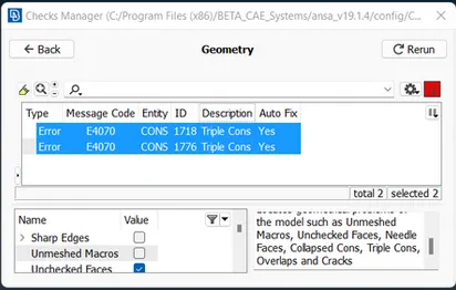
You can see the wireframe mode of our model in the image that is below. In this mode, you can see that our model only has one triple con, which is the important one, and that the others are double cons. Therefore, we are able to draw the conclusion that we have eliminated all topological errors, and we can now proceed to assigning the appropriate PIDs.
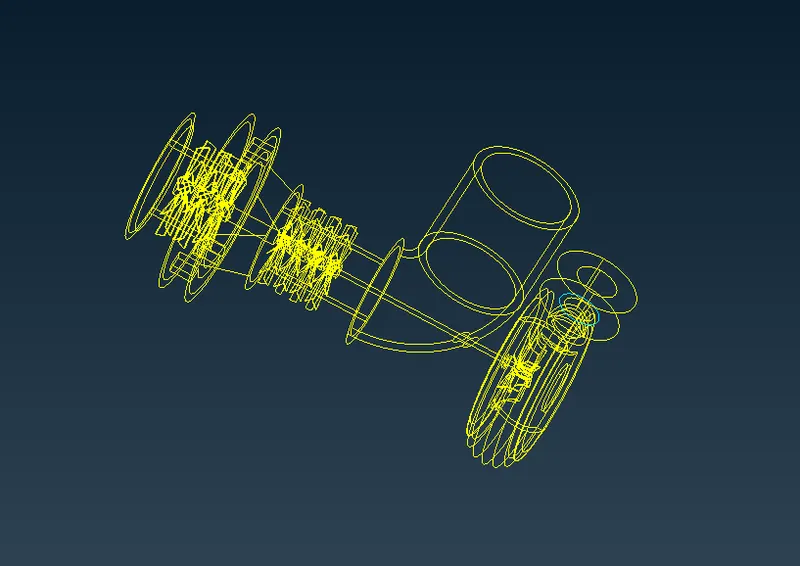
- In order for us to be able to do volumetric mesh, however, it is necessary for us to close the geometry wherever it is open, such as at inlets and outlets, before we can assign the PIDs. In the event that it is not closed, ANSA will display an error; therefore, it is essential that the geometry be closed.
4) Putting the Appropriate PIDs on the Items:
During this stage, we are going to differentiate the various components by assigning a name and a colour to each one, as well as the PID.
- This is also done in order to give names to the various boundary conditions that are associated with the various parts.
- Before we can start configuring PIDs, we have to turn on the cross hatches.
- If you open the properties manager at the very top, you will see that there are already some default PIDs assigned; in this case, all we need to do is change the names of those PIDs. In order to complete the geometry and add any remaining new surfaces, a new PID will need to be generated. In order to create a new PID, right-click on the properties manager, then click new, then select pshell twice, then give the new PID a name in the popup box, and then click ok. You can change the colour by doing a double click on the colour box, followed by clicking the ok button.
- In a similar fashion, generate PIDs for any inlets, outlets, etc., that are present.
- In this case, the shaft rotor possesses two distinct PIDs, but we combine them into a single PID to simplify things.
- After that, the next step is to give these PIDs to the different components of the geometry.
- In order to apply, we first select the PID that we want to apply in the PID manager, then right-click on it, then click the apply button, and finally, in the geometry, we select the cross hatch of the surface that we want to assign, and then middle-click on it. In a manner analogous to this, we are required to apply the PIDs that we have created. In order to calculate the PID, we first select the required surface using one of the many different types of selection that are available.
- Then, after assigning the PID, delete the empty original PIDs by using compress. These are the PIDs that do not have any components assigned to them.
- You can see that the entire geometry has been closed in the image that follows, as well as the list of PIDs that we have assigned to it.
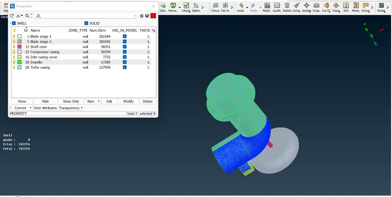
5) Settling on a size/length specification for the element:
After that, the following thing that needs to be done is to surface mesh the model by providing various mesh lengths for each different PID. Here, we give the blades and rotor a target length of one millimetre, the casings a length of five millimetres, and the impeller a length of two millimetres. You can see that the length of the blades has been reduced because this is a very important part of the CFD analysis, and it should be as refined as possible.
6) Choosing the type of meshing to be used and generating the surface meshing for the CAD model:
- In this step, the Meshing algorithm will be selected.
- In order to accomplish that, we follow the steps below:
- Navigate to Mesh Generation > spot Mesh > tria > drag and select the required model > click on the scroll button or middle mouse button on mouse to mesh (or) we can directly select visible under drop down menu of spot mesh instead of dragging and selecting the entire model after first separating the components of the model with NOT.
- After the meshing is complete, you are able to see problems. Because at the interface of these two components it is registered that we gave a length of 1 mm for the shaft and 2 mm for the impeller, it overwrote the mesh of 1 mm. Then, at the interface, the ANSA became confused as to whether to give 1mm or 2mm, so it essentially deleted the mesh.
- This occurs as we mesh the shaft rotor first and then we mesh the impeller. The mesh of the shaft rotor is gone after the mesh of the impeller is done Afterwards, the size of the element at the interface will change to 2 millimetres.
- After that, you should mesh the model once more. The same issue is observed at the intersection of the turbocasing and the rotor, as well as the intersection of the compressor casing and the rotor. Instead of adjusting the length once more, we will directly mesh the geometry in order to solve this problem.
- Then, after the meshing process is complete, you will notice a discrepancy here on the compressor casing as a result of the element length, which is 1 at the interface and 5 on the compressor casing. As a result of the abrupt change from 5 to 1, the elements are not of high quality.
- After that, in order to get rid of this, we create a patch by using cut under macros in the mesh deck in order to get a balanced gradient.
- The image below displays the model after the mesh has been generated for it.
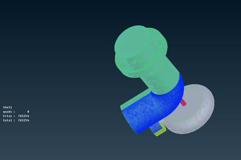
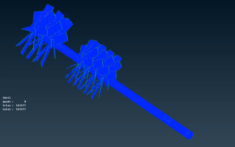
NOTE: In this case i used freeze command in case of Blades and Shaft Rotor only, so that we can lock the separate minimum & maximum target length as we can't perform on same target lengths of whole model because we can face error in case of spring, as we gave 5mm in last case to outer portion. The blue portion is because of freezing.
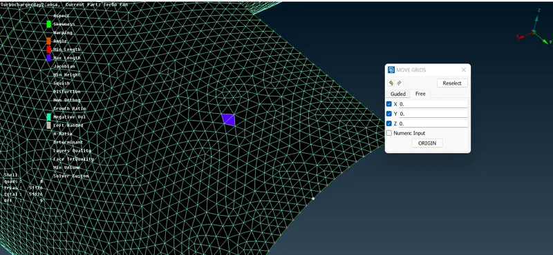
Using move command to improve off elements
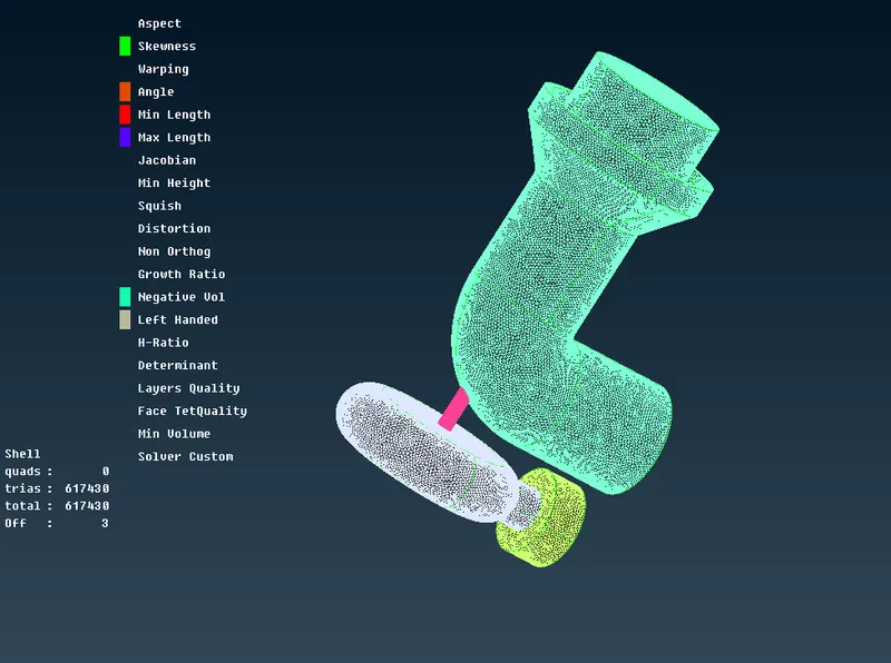
- Offelements should be kept to a bare minimum.
7) The creation of a volumetric mesh:
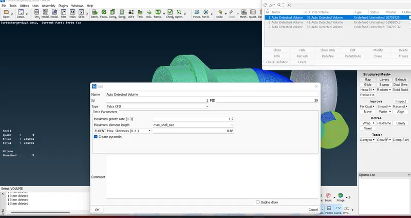
After that, the only thing that needs to be done is the volumetric mesh. Before we can proceed with the volumetric mesh, we will need to define it. Following the definition, it will produce 7 volumes automatically.
The figure that follows illustrates it for you.
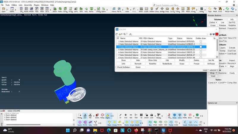
- Delete any volumes that are useless after they have been generated. We require the volumetric information that is included within the compressor casing and the turbocasing. Because the assembly has a volume of its own, the volume occupied by the compressor outercasing, blade shaft, and tubro casing has been deleted here. This is done because in the CFD analysis, we will be looking for flow occurring over the shaft or where fluid flow is occurring, and not for flow occurring within or along the thickness of the geometry. Since the interior is hollow and there is no flow, and since we are thinking about the flow over the blade, we have eliminated everything that isn't absolutely necessary.
- After eliminating, we are left with 3 volumes in which flow is occurring, and we will need to perform volumetric mesh for those volumes.
- Tetra CFD should be used for any unstructured volumetric mesh work that needs to be done.
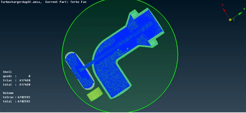
- By deleting some components of the elements, we are able to visually check the creation of a volumetric mesh by observing the presence of many elements inside as well as slots for blade attributes.
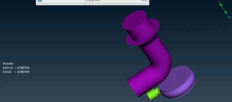
- You can see that the volumetric mesh has been applied to the 3 volumes in the following figure, which is showing where flow is occurrin
- The following illustration provides a cut sectional view for your review.
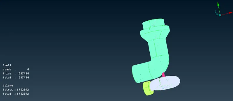
- Following the creation of the volumes, the completed model can be seen in the image that can be found below.
-
Conclusion:-
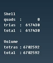
After the completion of the volumetric mesh, the number of tria elements has been determined to be 617430, and the number of tetra elements has been determined to be 6702592.
The graphic that follows demonstrates it for you.
The result of the learning is:
As a result of going through this procedure, we have acquired the knowledge necessary to correct any geometry problems, mesh the provided CAD model, and carry out volumetric mesh. While we were working on the face over the turbocharger, we realised that we needed additional hot points on the surface. This is something that we have now learned how to do. After that, we were instructed on how to set up necessary PIDs to various parts, how to define different element sizes or lengths, how to select the appropriate meshing type, and finally, how to build surface mesh. Before proceeding with the volumetric mesh, the model must first have a surface mesh created. The element size of the surface mesh is used to determine the element size of the volumetric mesh. Then, after some trial and error, we figured out how to produce volume mesh. After removing the volume that was created by the rotor, we found that there was an empty area at the location where the rotor had been before the volumetric mesh was applied. This was another thing that we noticed.
Google Drive Link: https://drive.google.com/file/d/1hLPIORGqCsTDB4ll1DerHefTj6Hd9NdB/view?usp=sharing