Week 3 Challenge
1. 1. primary load cases to be considered for design.
Aim and Introduction:
To determine the primary load cases for the design
Procedure:
Primary Loads are divided into two broad categories according to the way in which they act upon the structure or structural element. These are DEAD LOADS and LIVE LOADS.
Dead Loads are those loads which are considered to act permanently; they are "dead," stationary, and unable to be removed. The self-weight of the structural members normally provides the largest portion of the dead load of a building.
Live Loads are those loads which are transient and can change in magnitude. They include all items found within a building during it's life (people, machinery etc..,).
Result:
The primary load cases for the strcuture has been determined
2. What is One – Way slab
Aim and Introduction:
To define the concept of one way slab
Procedure/Explanation:
One way slab is a slab which is supported by beams on the two opposite sides to carry the load along one direction.
Ly/Lx >2
The ratio of longer span (lx) to shorter span (ly) is equal or greater than 2, considered as One way slab because this slab will bend in one direction
Result:
The One way slab concept has been determined
3. unit weight of structural steel and soil
Aim and Introduction:
To determine the unit weight of soil and steel
Explanation:
Unit weights are determined as per the code IS-875 part 1
unit weights of steel = 18.0 kN/`m^3`
Unit weight of soil = 78.50 kN/`m^3`
Result:
the unit weights of the steel and soil has been determined
4. sections that can be defined using Properties
Aim and introduction:
to determine the sections that can be define using the section properties tab
Procedure/Explanation:
The sections that can be defined using properties tab are as follows
- Circle
- Rectangle
- Tee
- Trapezoid
- Tapered I
- Tapered Tube
Result:
hence the sections that can be defined usign the properties tab is determined
5. Primary Beams
Aim and Introduction:
To discuss about the primary beam
Explanation:
The beams that are connecting columns for transferring loads of a structure directly to the columns are known as primary beams
Results:
The primary beam have been discussed
2. 1. factors and parameters that influence the design pressure intensity of a high-rise building.
Aim and Introduction:
To determine the factors and parameters that influence the design pressure intensity of building
Explanation:
The high-rise building is generally defined as one that is taller than the maximum height. The foundations of high-rise buildings must sometimes support very heavy gravity loads, and they usually consist of concrete piers, piles, or caissons that are sunk into the ground.
Factors affecting the wind pressure of high rise buiulding:
The main factors affecting the wind pressure distribution on a building: terrain roughness, surrounding buildings, aspect ratios, and wind direction.
Results:
The factors and parameters that influence the design pressure are determined.
2. load transfer process of a Reinforced Concrete Building.
Aim and Introduction:
To determine the load transfer mechanism of RCC building
Procedure:
Gravity load is the vertical load acting on a building structure, including dead load and live load due to occupancy or snow. Gravity load on the floor and roof slabs is transferred to the columns or walls, down to the foundations, and then to the supporting soil beneath.
Incase of the presence of the secondary beam the slab weight and secondary beam weight is transfere to the primary beam and from there it will be transfered to the beam and to the column.
Result:
The factors and parameters are determined
3. 1. One-Way and Two way slabs
Aim and introduction:
To determine the concept of oen way slab and two way slab
Procedure/Explanation:
The basic difference between One Way and Two Way Slab is that the bending moment occurs only in one direction i.e. the shorter direction in One Way Slab while in Two Way Slab bending moment occurs in both directions i.e. shorter and longer.
Bending moment occurs only in one direction i.e. the shorter direction in One Way Slab while in Two Way Slab bending moment occurs in both directions i.e. shorter and longer. The deflected structure is cylindrical in one way and the country shape of the deflected structure is like a dish or saucer in Two Way Slab.
Reinforcement for both type of slab is laid parallel to the shorter direction and the reinforcement parallel to the longer direction is distribution steel in one way slab. While reinforcement in Two Way slab it is laid in both the direction.
Result:
The one way and two way slab has been discussed in detail
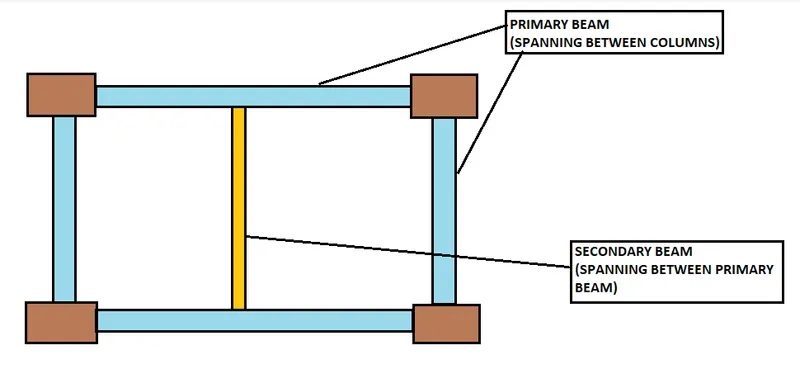
2. secondary beams.
Aim and Introduction:
To determine the functions of secondary beams with sketch
Procedure/Explanation:
- Beams that rests on the primary beam and transfers the load to the primary beam is known as secondary beam.
- These beams are provided for supporting and reducing the deflection of beams and slabs.
- Simply the main beams are supported on the columns and the secondary beams are supported on the main beams.
- Maim beams transfer the loads from the slab to the columns directly, secondary beams transfer the loads from the slab to the main beams.
Result:
Functions of the secondary beam has been determined.
3. Mention the Primary load cases.
Aim and Introduction:
To determine the primary load cases for the design
Procedure:
Primary Loads are divided into two broad categories according to the way in which they act upon the structure or structural element. These are DEAD LOADS and LIVE LOADS.
a) Indian Standards for load cases
IS-875 Part 1 - Code of Practice For Dead Loads
IS-875 Part 2 - Code of Practice For Live Loads
IS-875 Part 3 - Code of Practice For Wind loads
IS-875 Part 4 - Code of Practice For Design Loads for building and structures
IS-875 Part 5 - Code of Practice For Special loads and combinations
b) Load case parameters:
the load case parameters are factor of safety, unit weight of the material.
c) load cases
Dead loads are permanent or stationary loads which are transferred to structure throughout the life span. Dead load is primarily due to self weight of structural members.
The second vertical load that is considered in design of a structure is imposed loads or live loads. They are either movable or moving loads with out any acceleration or impact.
Wind load is primarily horizontal load caused by the movement of air relative to earth. Wind load is required to be considered in structural design especially when the heath of the building exceeds two times the dimensions transverse to the exposed wind surface.
Earthquake forces constitute to both vertical and horizontal forces on the building. The total vibration caused by earthquake may be resolved into three mutually perpendicular directions, usually taken as vertical and two horizontal directions
Result:
The primary load cases for the structure has been determined
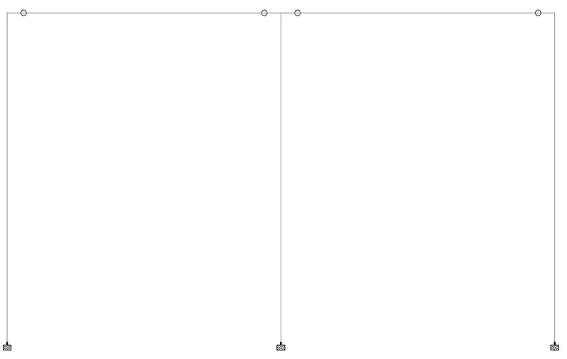
4. Steps involved in assigning Properties and Support to a model using STAAD Pro
Aim and Introduction:
To determine the steps involved in assigning properties and support specifications to the structure
Procedure:
Assigning properties:
- Create the model, then create the properties fo the material as per the cross sectional dimensions of the members
- Select the members to which the properties have to be assigned
- Click-and-drag a line horizontally from right to left across the columns to select them. This method will select any model object that your drag window crosses.
- click on the property whcih we created and assign to the material by three commands i) assign to view ii) assign to selected beams iii) use cursor to assign options to assign the properties to the member
- Now the property to the member have been assigned
Support specifications:
- select the node to which the supports have to be assigned
- create the support using the support tab either fixed or pinned or anyother support as you need
- click on the suport which we created and assign using the use cursor to assign command
- now the support has been assigned to the node which we have selected
Result:
The steps involved in assigning properties and support specifications to the structure have been determined.
5. Secondary beam
Aim and introduction:
To determine the steps involved in creating and assigning the secondary beam
Procedure:
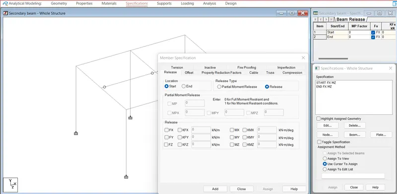
step 1: create the primary structure using primary beam and columns
step 2: Now create the node on the primary beam where the secondary beam have to rest
step 3: click on the add beam icon to  draw a beam from the nodes which is created on the primary beam for secondary beam
step 4: use the perpendicular intersection command under the add beam icon to connect the beam on either side of the primary beam
step 5: now the releases have to be made at start and end of the secondary beam to transfer the loads to the primary beam
step 6: the releases are done on the specifications tab click on the beam tab release Fx and Mz at start and end then click assign the releases have made at start and end of the secondary beam
after assigning the releases the run the analysis file we can check the BM at the ends of the secondary beam will be zero if so the porcedure for releases are correct
Result:
The secondary beam have been created and aslos assigned to the structure has been determined.
Practical:
Aim and introduction:
to create the building model as per the input specification
Procedure:
| Design wind speed Vz | = | Vb*k1*k2*k3 | ||
| Location | = | Darjeeling | ||
| Basic wind speed Vb | = | 47 | m/s | |
| where; | ||||
| k1 | = | 1 | Probability factor | |
| k2 | = | 1 | terrain ht factor | |
| k3 | = | 0.8 | topography factor | |
| Design wind pressure Pz | = | 0.68Vz2 | ||
| Height | k2 | Vz | Pz | Pz in kN |
| 4 | 0.8 | 30.08 | 542.8838 | 0.543 |
| 8 | 0.8 | 30.08 | 542.8838 | 0.543 |
| 12 | 0.8 | 30.08 | 542.8838 | 0.543 |
| 16 | 0.8 | 30.08 | 542.8838 | 0.543 |
| 20 | 0.8 | 30.08 | 542.8838 | 0.543 |
Result
The wind pressure for the Hospital building have been calculated as per the Indian code IS-875 part 3
2. Dead load and live loads
Aim and Introduction:
To calculate the DL and LL for the Hospital building
Procedure:
step 1: assume the sections properties to calculate the DL and LL
Step 2: cross section for the beam is taken as 300x450 mm and column as 300x400mm
step 3: the dead load nothing but the self wt of the structure multiplied by the unit weight of the material
for 0.3x0.45m deep beam material density = 25 kN/`m^3`
therefore Weight of beam = (0.3 x 0.45) x 5 x 25 = 16.875 kN
U.D.L in the beam = 16.875/5 = 3.375 kN/m (pt load to UDL)
Weight of slab = (1 x 1 x slab thickness) x RCC density
Weight of slab = slab thickness x RCC density
For 0.15 m thick slab the calculation will be as follows-
Weight of slab = 0.15 x 25 = 3.75 kN/`m^2`
Result
The calculation of DL and LL for the Hospital building is calculated