Week 2 Challenge
1. 1. How will you assign Circular section to column?
Aim and Introduction:
To assign a circular section to a column
Procedure:
Step 1- Create a new model for column
Step 2- Create the geometry firtst, enter the origin (0,0,0) for first node in node table
Step 3- since it is a column (vertical member) you should copy paste the 2 nd node in the Y direction
Step 4- Next specify the property as we want to select the cross section of the column since, it is circular column we want to provide diameter of the column
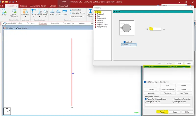
Step 5- click ok now the property for the column has been created now you can assign the property to the member
Now the circular column has been created.
Result:
The circular column has been created with the specification.
2. Unit system to a .std model file
Aim and Introduction:
To determine unit system to a staad file
Procedure:
We can assign the unit system for a model in two ways as in the initial stage of creating the model and also after
creating the initial model we can change the units with the menu options
method 1 you can choose the unit systems with which the model has to be created whether as a metric system or english unit system
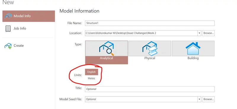
method 2 while in middle of the modelling if you want to change the unit systems you can go to view display options
and change the units in your working model for your convinience

3. parameters to be specified while using “Bay Frame”
Aim and Introduction:
To determine the parameters specification while using bay frame options in structure wizard
Procedure:
structure wizard is an option provided by default in staad pro to create the model at an ease process
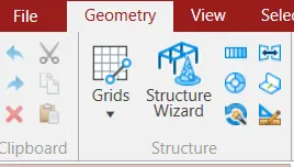
Goto--> Geometry ---> structure wizard ---> select frame models form the model type drop down list and select the Bay frame option
after selecting the option you want to input the parameters like length of the building , width, height, No of bays along the length, No of bays along the height, No of bays along the width as shwon in the image below
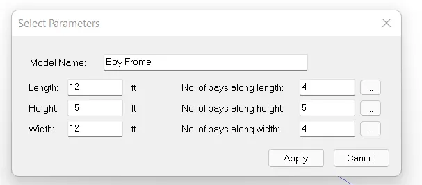
Result:
The parameters for the bay frame model has been successfuly given and the model has been genetrated as per the plan
4. codal standards incorporated in STAAD Pro software.
Aim and Introduction:
To determine the codes incorporated in staad.pro
Procedure:
As the codes are applied after the modelling and analysis of the structure
In the design part only we can select the codal standards, as few codal standards that incorporated in staad pro are as follows
1. Indian Standards
2. British standards
3. AISC srandards
4. Canadian standards
Result:
The standards incorporated in Staad are mentioned above and are determined
5. Design compressive strength for a RCC section.
Aim and procedure:
To specify the compressive strength of the RCC section.
Procedure:
After the analysis have been done we want to proceed further with the design of the RCC structures
In that case we want to define some parameters as Fc,Fy, Main, etc
Strength Fc is characteristic strenght of the concrete such as M20, M25, M30 etc..,
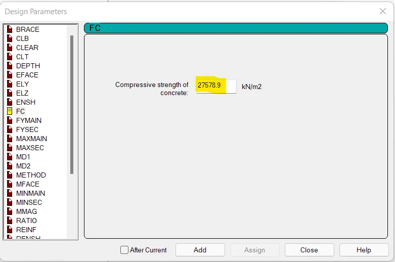
Another method we can change the compressive strength is using the command file, where we can directly change the FCu value in editor mode
Result:
The Compressive strength have been specified for RCC section.
2. 1. “Input” steps involved in RCC design.
Aim and procedure:
To determine the steps involved in RCC design.
Procedure:
Step 1: You need to prepare the geometry of the RCC structure.
Step 2. Then specify the properties for the structure for columns and beams.
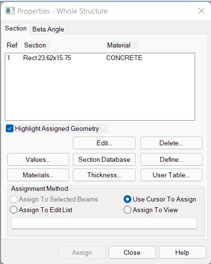
Step 3. Then assign the materials to the structure in materials tab.
Step 4. After modelling and loading has been done Go to analysis and design tab define the analysis commands as per the structure and run the analysis.

Step 5. Finally go to design tab and defien the design parameters and code selected as per the country the strucutre is to be designed.
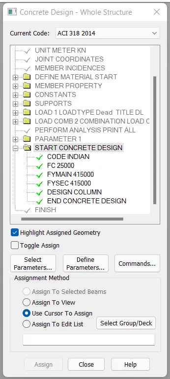
Step 6. Run the design command for RCC design of the structure
Result:
The input steps for RCC design have been determined
2. Fixed and Enforced support condition in STAADPro.
Aim and procedure:
To determine the difference between the Fixed and Enforced support condition
Explanation:
When the FIXED type of support is specified, for those degrees of freedom which are to be treated as fully restrained, STAAD assumes the displacements to be known quantities whose value is zero.
When the ENFORCED type of support is specified, for those degrees of freedom which are to be treated as restrained, STAAD assigns a spring with a very high spring stiffness. Those degrees of freedom which are free to displace are assigned springs of zero stiffness. Hence, for all the 6 degrees of freedom at such supports, the displacements are calculated.
Result:
Difference between the Fixed and enforced suport condition have been determined.
3. 1. Steps involved in analysis of a model using STAAD Pro.
- On the Model ribbon tab, select the Grid tool in the Create group.
The Create Grid dialog opens. - Supply the grid details:
- Type Grid 1 in the Name field.
- Select XZ as the Plane.
- Leave the Creation Method as By Spacing.
- Type 3 in the Number of Spaces in X and 2m in the Grid spacing X field.
- Type 2 in the Number of Spaces in Z and 2m in the Grid spacing Z field.
- Click OK. The grid is created.
- Orient the view from the top:
- If the rotation controls are hidden, click the rotation widget in the lower-right corner of the view window.
- Select the Switch to top view tool.
- Click the rotation widget again to hide the controls.
Method 2:
Another method by which we can create the model are using structure wizard method
- Geometry on the menu bar and geometry tab click on the strucutre wizard icon
- frame model or bay type will be there which was provided by the staad by default
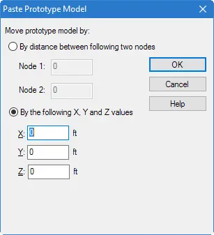
- Select File > Merge Model with STAAD.Pro Model. A dialog prompts you to confirm you want to merge this prototype with your current STAAD.Pro model.
- Click Yes.
- Paste prototype model dialog box will open as below
3. different support conditions in STAAD Pro.
Aim and procedure:
To elobarate the different support conditions availabe in staad pro
Explanation:
There are different support conditons which are available in the staad pro they are,
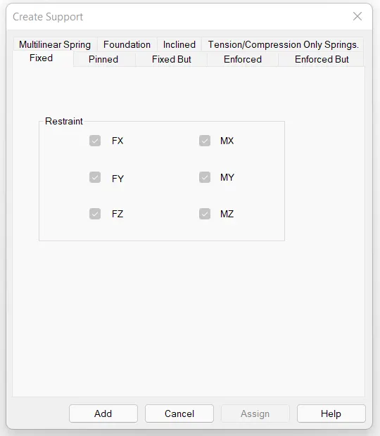
Fixed support: fixed support can carry moment, vertical And horizontal reactions, the DOF in fixed support is 0
Pinned support: pinned support can only support vertical and horizontal reaction, DOF in pinned support is 1
Fixed but: type of support is specified, for those degrees of freedom which are to be treated as fully restrained with some displacements
ENFORCED or ENFORCED BUT type of support is specified, for those degrees of freedom which are to be treated as restrained, STAAD assigns a spring with a very high spring stiffness - translational stiff springs for translational restraints, and rotational stiff springs for rotational restraints
Results:
Hence defferent support conditions have been discussed with their respective conditions.
4. Stress distributution in staircase slab.
Aim and procedure:
To determine the stress distribution in staircase slab in staad pro
Explanation:
Create the nodes for the going slab and landing slab
After creating the nodes for going slab and landing slab assign the plates to the slabs either clockwise or anti clockwise
Goto properties and assign the properties for plate thickness
Generate the mesh for the plate as quadrilateral meshing and generate it.
apply the loads and perform the analysis
after analysis part define the design parameters for design and run the analysis
Go to --> Results --> plate results --> Diagram dialog box ---> Plate stress contour --> slect the load case for the combination and stress type as maximum absolute ---> click apply to view the stress contours for the staircase slab.
Result:
Hence the stress distribution for the staircase has been determined
5. SFD & BMD
Aim and procedure:
To view the SFD & BMD in different ways.
Procedure:
First you must Analyze the file. Select Analyze from the Staad.Pro top menu bar. Select the Analysis option. After this, click on Run Analysis at the bottom of the small window dialog box.
After the analysis of the file is completed, click on the Done button.
Next, we go to the Post Processing mode to view the forces and results graphically.
To enter into the Post Processing mode, select Mode from the top menu bar and select Post Processing. Remember that if your analysis is not complete, you will not be able to access the Post Processing mode.
By default, the deflection diagram always opens up in the post processing screen of Staad.Pro.
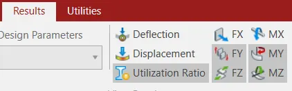
To view the Bending Moment Diagrams, select the Beam page from the left side. From the top menu bar, choose Results - View value. Under Ranges, choose All. (The All button means the Bending moment diagram will be displayed for all members.)
Under the Beam Results tab, you will see the options Bending, Shear, Axial, Displacement and Stresses.
Make the appropriate choice.
Click on the Annotate button. Then click on the close button.
Here are a group of of other options to view BMD, SFDs
To view the bending moment diagram for individual members you may go to the Beam > Graphs page on the left and click on any member and the BMD, SFD and axial force diagrams for the member would be displayed on the right.
Alternately you may also double click on any member to bring up the query box and go to the Shear Bending tab to see the bending moment or shear force diagrams for that member.
PRACTICAL:
1. Analyze the following structural elements and validate the results
A. Simply Supported Beam
a. A Simply supported beam with two point loads symmetrically placed
Aim & Introduction:
to create a 20m with two point loads
Procedure:
Step 1: Create a geometry for a beam of span 20m as shown below
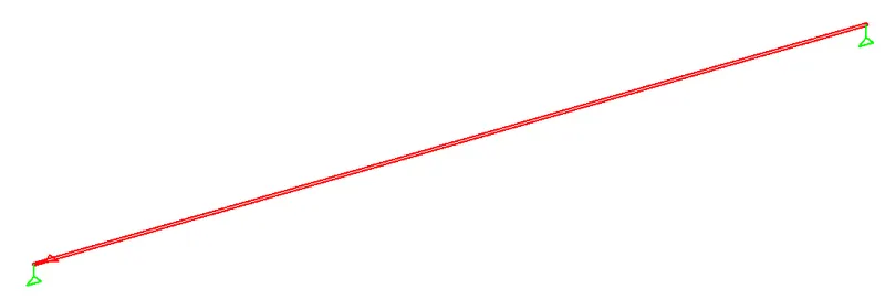
Step 2: create a support specifications which satisfies the SS condition using fixed but condition
As for SS condition we need to restrain Fx and Fy alone and of roller support we want to restrain Fy on the other end as shown above image
Step 3: Analyse the beam by adding perform analysis command
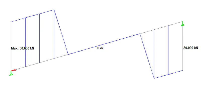
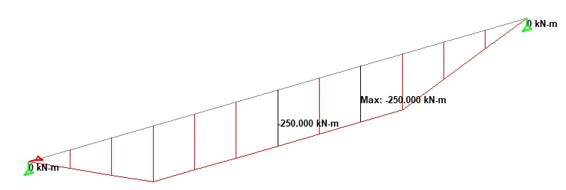
Step 4: now we can see the SF and BM from the beam results from post processing results
SFD
BMD
B.Fixed Beam
Aim & Introduction:
to create a 16mwith UDL
Procedure:
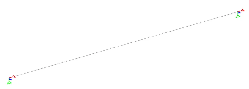
Step 1: Create a geometry for a beam of span 16m as shown below
Step 2: create a support specifications which satisfies the Fixed condition using Enforced but condition.
As for fixed condition we need to restrain Fx, Fy & Mz for both end as shown above image
Step 3: Analyse the beam by adding perform analysis command
Step 4: now we can see the SF and BM from the beam results from post processing results
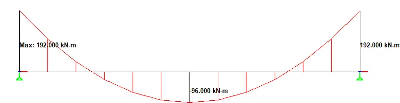
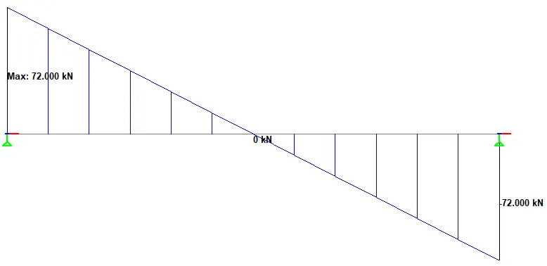
Results:
Hence the SS and fixed beam have been analysed for two different conditions with udl and tow point loads have been analysed