Week 1 Challenge
1.1. Aim and Introduction:
To explain the steps involved in uploading .std file through webmail
Procedure:
- Select the Share page on the Start page.
- Select ProjectWise.
- Select the File Name of the STAAD input file you want to share. Click Browse to navigate to the file using a Windows open dialog.
- Click Add. You are prompted to log in to a webmail data source
Result:
The .std file has been successfully shared through webmail
1.2. Aim and introduction:
To list out the materials designed in Staad Pro
Procedure:
Following are the materials that could be designed using Staad pro
- Concrete
- Steel
- Aluminium
- Timber
Result:
Materials designed using staad pro has been listed
1.3. Possibility of capturing the image in staad pro
Aim and introduction:
To capture image in Staad Pro
Procedure:
Yes we can capture the images in Staad pro and Following are the steps to take pictures
Goto Utilities and then click on Take picture tab to capture the image
Result:
photo capturing steps have been explained in procedure tab
1.4. Creation of model by different ways
Aim and introduction:
To create model by various steps
Procedure:
There are three ways in creating a model which are
- Analytical method
- Physical method
- Building method
Result:
The various ways of creating a model have been discussed
1.5. steps followed to assign properties in a model.
Aim and introduction:
To assign properties to members in a model
Procedure:
Create the profile you want to assing to the member
Select the profile to use and click OK.
Use the cursor to click on members with this property.
Result:
The properties has been assigned to the model
2. 1. Six design parameter involved in RCC design.
Aim and introduction:
To determine the design parameters in RCC design
Procedure:
The different design parameters are as follows
- Cover
- Fu
- Fy
- Unbraced length (Ly,Lx,Lz)
- Main
- Depth
Result:
The design parameters have been listed
2.2. Aim and Introduction:
To determine the different types of cursors used in staad pro
Procedure:
Nodes cursor, Beam cursor, Plates cursor, Surface cursor, Solids cursor, Geometry cursor.
Results:
Different cursors have been listed
2.3. Aim and Introduction:
To generate different views in staad pro
Procedure:
the different view are generated using the view cube option from diffeent direction (x,y,z,isometric view)
Goto view tab click on the various options used to view the model
Result
Different views has been generated
2.4. Simply supported beam procedure
Aim and Introduction:
To determine the procedure for simply supported condition in staad pro
Procedure:
- Start Staad pro application
- Click new project
- Click commands then member property Prismatic
- Goto Commands then Support specifications Fixed on both ends of the beam
- Now it is conisdered as a simply supported condition for the beam
Results:
Simply supported conditon has been explained
2.5. DBR process
Aim and Introduction:
To determine the Topics included in DBR process
Procedure:
- Introduction
- Structural Layout
- Loads and load combination
- Analysis and design methodology
- Quality and assurance plans
Results:
The topics included in DBR process have been listed
2.6. Multi material design
Aim and Introduction:
To Explain the concept of multi material design
Procedure:
It has predefined material in it, as it has concrete steel aluminium and timber you create geometry first and apply the material to the geometry and run the analysis
Results:
Multi material concept has been explained
3. 1. Strucutre system in Staad
Aim and Introduction:
To determine the different structure system in the staad
Procedure:
There are four types of structure system
- plane
- space
- frame
- truss
all these four systems are differentitated based on the geometry, loading, deformations and joints
Space and truss has geometry, loading and deformations in 3D
Frame is 2 dimensional and joints in truss is always pinned
3.2. Coordinate system in Staad
Aim and Introduction:
To determine the coordinate system adopted in staad
Procedure:
There are two cordinate system adopted in staad they are;
- Global Axis co ordinate system: It is Fixed and non variable co ordinate system, irrespective of member orientation or building orientation
- Local axis system: It is a variable system and depends on the member orientation. Since longitudinal axis is always local X and local Z varies
Result
The coordinate system of the staad is explained
3.3. DBR and its uses:
Aim and Introduction:
To determine the uses of DBR
Procedure:
DBR simply called as Design Basis Report
DBR USES: To specify and compile the data required for the analysis an design of structural elements of the project.
It also depicts the assumptions made in the design to develop the construction documents for the project
It also help avoid the scope creep of the project.
Result:
DBR and its uses has been clearly explained
3.4. Different types of analysis options in STAAD pro.
Aim and Introduction:
To Determine the different type of analysis options in staad pro
Procedure:
- p-delta analysis,
- geometric non-linear analysis,
- Pushover analysis (Static-Non Linear Analysis)
- buckling analysis.
- perform cable analysis
- perform direct analysis
- perform imperfection analysis
Result:
Hence the different type of analysis has been determined
3.5. Fixed and Fixed But condition
Aim and introduction:
To determine the difference between the fixed and dixed but condition.
Procedure:
When the FIXED type of support is specified, for those degrees of freedom which are to be treated as fully restrained, STAAD assumes the displacements to be known quantities whose value is zero.
For the FIXED BUT support type, if any degrees of freedom are assigned a spring using the KFX thru KMZ terms, those are treated as unknowns and their displacements are calculated.
Results:
Hence the difference between the fixed and fixed but is determined
Practical:
1. Create a STAAD Model with the following Specification
a. A beam of span 16m
b. Support : Fixed on one end and Roller support(Horizontal) on the other end
c. A point load of 50 kN at the mid-point
d. Draw SFD and BMD using software
a. Create a node by at co ordinates (0,0,0) and copy paste the node to certain distance which you want say 16m in our case
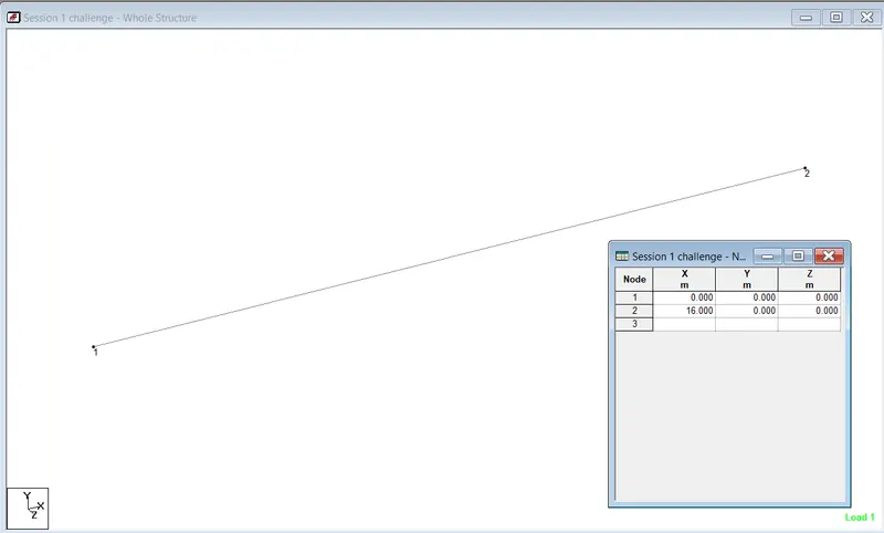
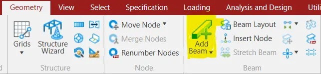
Create a beam between the node points by clickin the Add beam icon
b. After adding the beam for the length you need assign the section property and the material for the beam
Goto ----> Properties ---> Define ---> select the desired cross section and type the cross sectional dimensions
--->0.23mx0.23m
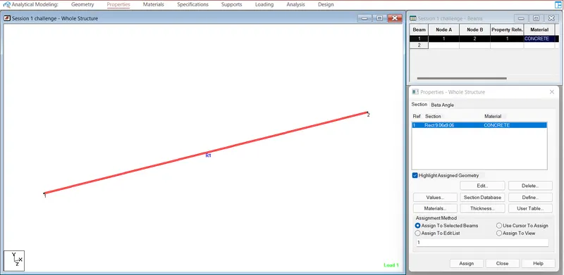
Assign materials in Materials tab as Concrete
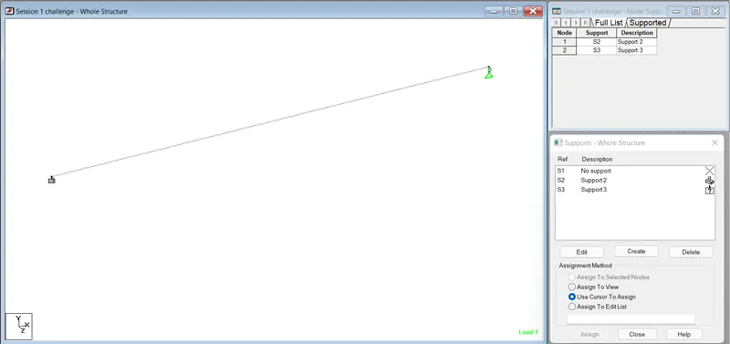
Now assign the support condition to the beam as one end fixed and one end roller as shown
Goto ---> Supports tab -----> Create the support conditions you need as fixed or pinned directly from the staad which it has by default
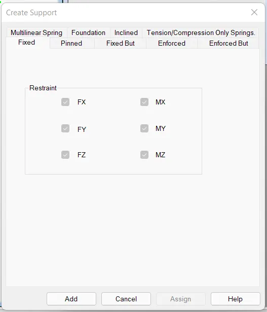
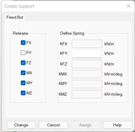
for roller support which is not present by default we want to customise the support as Goto---> Fixed but support and release only Fy and tick other things as shown in below image
c. A point load of 50 kN at the mid-point
now to apply load to the beam which we created click on the loading tab click on Load case details
then click on Add and add load case (DL, LL,etc) as shown
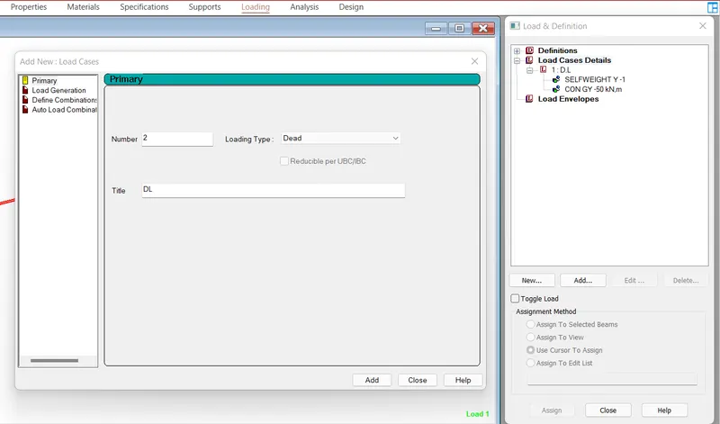
To Apply point load of 50kN at the midpoint Click on the load case DL which you created then click add
Click on Concntrated force then input the force 50kN and click add
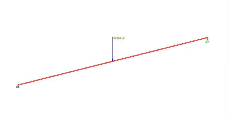
Now the point load for 50kN will be created click on the assignments methods whcih you need to apply on the beam
now the pt load will be applied on the midpoint of the beam as shown
d. SFD and BMD
after the application of the load now you want to analyse the beam for the load case details
Goto---> Analysis and design ----> Run analysis ---> go to post processing mode
Goto ---> Results ---> click on FX FY for the shear diagrams and Mx My for moment diagram
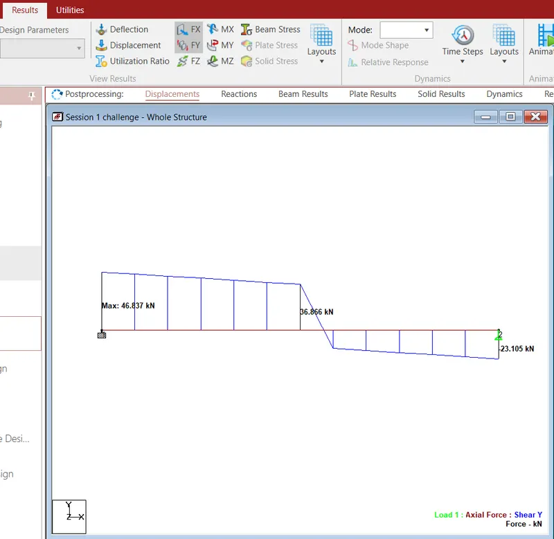
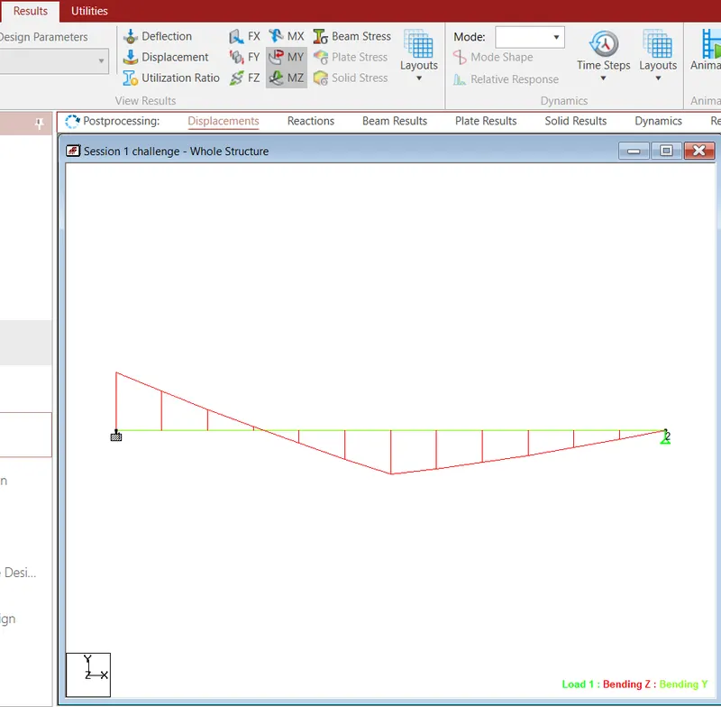
Thus the Practical session using Staad pro has been successfully created