Week 3:- BiW Fixture Design Methodologies Challenges
Q1. Design Methodology
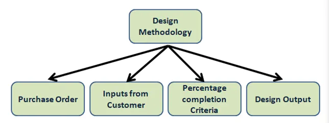
Different design methods are simply the procedures used while conceptualizing a fixture design. Design methodology is divided into four sub categories:
- Purchase Order.
- Inputs from Customer.
- Percentage Completion Criteria.
- Design Output
Purchase Order: A purchase order essentially serves as the customer's authorization to begin work. The first formal offer made by a buyer to a seller outlining the types, quantities, and negotiated pricing for goods or services is called a purchase order. It is employed to regulate the acquisition of goods and services from outside providers. An indent is a purchase order that is frequently made through an agent under predetermined terms of sale. A purchase order's issuance does not constitute a contract in and of itself. If there is no prior agreement, the seller's acceptance of the order creates the contract between the buyer and seller.
Inputs from Customer: Every customer has unique requirements, and each one could even have their own CAD, electric, pneumatic, and raw material standards.
- Each client also provides distinct inputs and anticipates different results, for example, 2D drawings, process sheets in XlS and pdf, CAD design formats, layout formats.
- Spot welding BOM for the parts that need to be welded.
- Data from CAD panels, or 2D drawings of the assembly and each panel.
- Thickness of the sheet metal panel is a key factor in determining whether to weld two or three metals.
- Weld information clarity from drawings, when welding with two or three metals.
- Cycle time can be computed using either a robotic or manual welding method.
- Raw materials requirement.
- Standards like pneumatic items, toggle clamps, bearings, screws, and dowels are examples of purchased parts.
- PLP (Principal Location Scheme) of each panel individually and collectively.
Percentage completion criteria: It involves estimating how many days the project will take to finish in its entirety.
- It is adhered to during the fixture's designing and shipping phases.
- It checks whether the number of tasks set out to finish in the allotted time has been reached.
Design Output: Output consists of 3D models, 2D sketches that serves as the detailed portion, bill of materials, and other relevant papers. Some tools are classified as unitized tools if they have various units on a single base, such as a fixture with numerous units.
- The unit's index and location on the tool base are shown on the key sheet.
- Layout sheets are comprehensive drawings of individual units that show all their parts. Tools that are not unitized that can be fully described on the layout sheet.
Q2. Inputs required to design Fixture
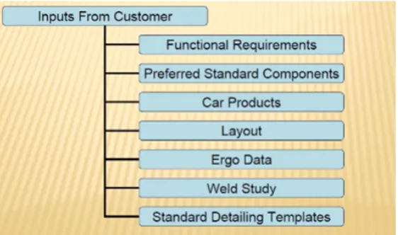
Functional requirements: The customers' input will determine the fixture's function, such as whether it will be used for welding, riveting, gluing, or whether it is a checking fixture, among other things. It is one of the fundamental needs to get from the client before designing a fixture.
Preferred standard components: Different companies adhere to various standards. By adhering to the standards while designing and producing parts, a lot of time and money is saved, which will naturally shorten the length of the projects. If the parts are standard, switching from a used fixture to a new fixture is simple and inexpensive.
Car products: Each station's locating pins, rest, clamp, dump, and slide unit information is provided, as well as the information on the clamp, dump, and slide stroke opening sequence.
- Assemblies: If two parts' dimensions fall outside of a predetermined range of values, they will frequently fit together.
- Interchangeability: If a replacement component is used, it must, within specific tolerances of variation, be an exact replica of the original part.
- From part to part, an object's usefulness and size or form have different relationships.
Layout: The intended purpose of a layout is to comprehend information on the placement of fixtures and robots, the working space used by each robot, the fixtures allotted to each robot to carry out the process, etc. To comprehend the process, the layout displays the full assembly schedule. It also contains,
- Parts flow.
- Station angle.
- Link to a subassembly.
Ergo Data: Ergo data provides details of engineering data on human factors between the operator and his working environment. When developing the fixture, we must take the requirements of the consumer into account. The information or inputs pertaining to the operator and his working fixture are obtained through ergo data. The primary purpose of ergo data is to increase operator comfort, which may increase productivity and cycle time efficiency.
Weld study: The crucial consumer input is the weld study. It provides an analysis of the specific welding gun to be used, the number of places to be welded, the order of welding, and the location of welding on the components. In essence, weld studies that consider weld gun parameters, weld matrix, and weld spots make the operator more comfortable, which may increase cycle time and production efficiency.
Standard detailing Templates: We must comply to the detailing templates in accordance with the client criteria as these inputs contain 2D CAD design detailing templates.
Q3. Input from Car products:
Each station's locating pins, rest, clamp, dump, and slide unit information is provided, as well as the information on the clamp, dump, and slide stroke opening sequence.
- Assemblies: If two parts' dimensions fall outside of a predetermined range of values, they will frequently fit together.
- Interchangeability: If a replacement component is used, it must, within specific tolerances of variation, be an exact replica of the original part.
- From part to part, an object's usefulness and size or form have different relationships.
- Datum reference in GD&T: When processing a material or measuring the dimensions of a target, a datum is a plane, a straight line, or a point that is used as a reference.
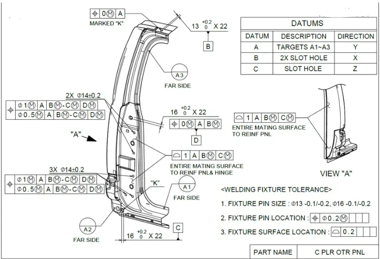
Fig. GD&T in fixture design - 2D drawings: provides listing of the components that will be put together in the fixture. The list includes details such as part name, part thickness, fixture revision, and part number.
- Clamp Plan:offers information on where pins, rest units, clamp units, dump units, etc. are located. No modifications to the clamp layout or positions should be made without customer consent as it provides information on the precise location of the clamping units.
- Process flow for assembling a product: It provides information on the stages of the assembly process, such as how the pieces go from one assembly to another when the joining process is complete.
It displays the procedure or order of steps to be followed in a component or panel.
Q4. Clamp Plan:
A clamp is a tool that offers an invariant position in relation to an external loading mechanism. In other words, the act of clamping creates a locking effect that, by friction or a different kind of mechanism, maintains a location's stability and prevents it from changing until an external force is strong enough to override the locking effect. Therefore, a strong enough clamping force must be applied to withstand such motions when a cutting force is creating a load or moment on the workpiece.
Clamp requirements:
- The workpiece must be kept firmly in place while being operated on.
- The clamping device must be swift acting in order to minimize the amount of time needed to load and unload the tool.
- The clamping must be positive when being subjected to vibration, chatter, or severe pressure.
- The workpiece must not be harmed by the clamp.
Clamp Plan: By specifying a set of coordinates for a certain point, it provides information on the precise location of the clamping units. Where exactly we arrange clamping units and certain pin units is a very significant input we obtain for the automobile products according to the clamp plan.
Q5. Purpose of a layout:
The goal of a layout is to comprehend information on the placement of fixtures and robots, the working space used by each robot, the fixtures allotted to each robot to carry out the process. To comprehend the process, the layout displays the full assembly schedule.
- The robot's circle represents its sweeping area and illustrates how easily it may be reached, especially in small spaces.
- Parts flow, station pitch, robot stations, accessories like tool changers and tip dressers, subassembly linkages, platform height, and loading/unloading sequence/height are all provided by the layout.
- The layout sheet will advise you of where each fixture has been installed and where the robots will be working.
- The region surrounding the robot that is restricted to a certain circle is referred to as the trapped area of that robot on the layout sheet.
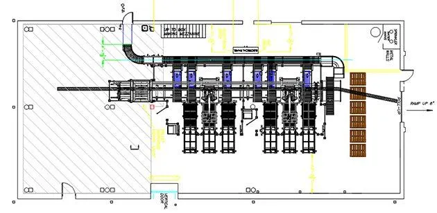
Fig. Layout Sheet - Parts flow: It depicts the movement of components from one station to another when a procedure is complete on an assembly line or in a shop floor.
- Station pitch is the measurement of the separation between the two stations. The arrangement demonstrates the little space between the two stations.
- Sub-assembly link: The connection between the assembly fixtures and the primary assembly line is known as a subassembly link. It demonstrates how the main assembly line is connected to the subassembly fixtures.
- The architecture that provides the prior information, such as the flow of components, station pitch, robot stations, etc., is utilized to comprehend how robots operate and what fixtures are designated for them as well as space restrictions.
- By taking the layout into account, the designer may create concept sketches for fixtures without worrying about assembly line conflicts.
Q6. Ergonomics data:
The information or inputs pertaining to the operator and his working environment are obtained through ergo data. The primary purpose of the ergo data is to increase operator comfort, which may enhance cycle time and production efficiency.
Design has a role in ergonomics:
- A setting that is suited for the worker involved.
- Equipment and controls that reduce physical stress on the worker are necessary to increase efficiency.
- a setting that is suitable to and most productive for executing a task.
- job and global organization that is favorable.
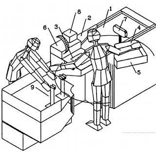
Advantages of ergonomics
- Improved state of operation.
- Reduce operator’s physical activity.
- Improved manipulation of machine levers and controls, and improved viewing of instrument displays.
Q7. Weld Study:
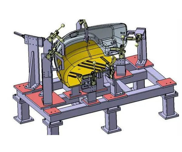
It provides an analysis of the specific welding gun we use, the number of places to be welded, the order of welding, and the location of welding on the components. Weld gun information, a weld matrix, and weld sites are all included in a weld study. The weld spots are often shown as spheres.
- Geo-welding points: According to the information in the design, these welds will decide where the panels should be placed. In the weld research inputs provided by the clients, the Geo weld spots are shown as a red sphere.
- Re-spot welding point: The strength and stiffness of the panel and its components will be determined by these welds. Sphere in green are Re-spot weld points.
Q8. Condition for percentage completion in designing stage
- When developing and shipping welding equipment, a percentage of completion condition is adhered to.
- This percentage completion criterion is used to determine if the project is on schedule for delivery to the client, as promised.
- Additionally, it assists us in determining the project's stages, such as how much of each stage is complete currently and which ones still need to be finished for the project to be finished on schedule.
To determine the proportion of the job that has been completed, the percentage completion criteria is broken down into four steps.
- Conceptualization and input: The project completion percentage for this object will range from 0% to 25%. The project will advance to concept approval and simulation check, the second step in the % completion criterion, when input and concept design are finished.
- Concept approval and simulation verification: In this case, the project's percentage completion criterion will range from 25 to 40 percent.
- Design freezing and detailing: Here, the project's percentage completion standard will range from 40 to 85%.
- Check and final dispatch: In this case, the project's percentage completion criterion will range from 85 to 100 percent. Following the inspection, the project will be successfully delivered to the client.
Q9. Output in Design
In the design of a BIW fixture, designing a specific component is not just a matter of creating the CAD file; rather, the customer must also receive submissions of numerous documents, including 3D documents, 2D documents—which are used for detailing—and other factors like BOM.
- Unitized tools: When testing unitized tools, two different types of drawing sheets are needed: a layout sheet and a key sheet. Therefore, fixtures are an example of a tool that has been unitized. For instance, welding fixtures for full assemblies where everything is included, including pin and clamp units, rest units, and panels.
- Key-sheet: A list of the units which are located on the tool base. It will include a numbered balloon graphic with the units and an orthogonal image of the fixture. The key sheet will show the placements and location of that specific tool on the tool base, where precisely the tool is placed, and what is his exact position in each area. As a result, it effectively functions as an index of units and placements on the tool base.
- For the non-unitized tool, a layout sheet is a comprehensive representation of each individual unit that shows all its parts.
The following criteria should be met by the design output:
- Whenever feasible, approved standard components should be utilized.
- Design must be straightforward and affordable.
- It must adhere to all current ergonomic and safety standards.
- Each design must have enough error proofing provisions such as proximity switches, rough locators, etc.
- The moving parts must be as light as possible while still being as strong as possible.
- Design clearance and ease of access for standard upkeep and servicing.
- Any moving equipment must take motion control into account.
- Clamps and welding guns must be validated by the designer.
Q10. Structuring a design tree
Where, every assembly and component have a name that adheres to a particular standard. Different clients will have different standards for how a design tree should be structured.
- An essential procedure that aids in determining which project, tool, or unit a certain part or assembly it belongs to. This aids in preventing mistakes from occurring during design, production, assembly, inspection.
- Knowing how many identical or different sorts of products are being used in the assembly might be useful.
- The base unit will be the initial unit designed when creating a fixture.
- All the manufacturing parts should come before the standard parts in a structure tree, and vice versa.
- A structure tree makes it simple to analyze or comprehend the components of assemblies.
There are several conventional practices for naming the assemblies, components, and units, which are detailed below.
P001_Z03_ST09_00_00_R
- P001- Represent the project/part name.
- ZO3 - Zone name/ Panel name will also be mentioned in some case.
- ST09 - Station name/ J03 - jig name will be mentioned sometimes.
- 00 - Unit name.
- 00 - Part number.
- R/L- Is representing the right-hand side/ left hand side of the panel.
Q11. Units and it’s types:
A fixture is made up of several units attached to a common base, which acts as a common support for the units where they are fastened. A unit is a device with a specific purpose, particularly one constituting the core of a complicated mechanism. Each unit has its own goals and functions.
It is divided into two categories:
- Unitized tools: Tools that are part of numerous units or have multiple tools inside them are referred to as unitized tools. These are the tools that need to be displayed in both key-sheet and layout sheet forms.
There are primarily two sorts of unitized tools.
- Simple units: These units have very simple designs and need very simple production processes. They are categorized as:
- Rest unit: This is a testing device without an upper clamp, a force application, or a cylinder attached to it. Typically, it has a riser, a blade, and a few rest mylars.
- A unit with a fixed pin is one that cannot have its pin moved.
- Retract pin unit: The opposite of a fixture that may be raised and lowered utilizing retractable pneumatic cylinders, allowing for a specified amount of retraction.
- Rough locator: It is a component designed to help the operator find the automobile panel on the pins in the proper location. A rough locator may be a manufactured part or a standard part.
- The sensor unit detects if a panel or specific component is there or not. Each of the ten pieces of the component, for instance, will have a sensor attached to it.
- Base unit: It serves as the foundation for all subsequent units.
- Complex Unit: Examples Slide unit and Dump Unit
- Non unitized tools: The purpose of non-unitized tools is to maintain the component on it as a stable unit without adding any process capability to it.
Examples:
- Bring out carts
- Flip the script.
- Robotic grippers
- Stands
Q12. Fixed Pin units & their purpose
With the help of pins, they are used to locate automobile panels. These have been assembled and already fastened so they cannot move up and down.
General parts of a Pin Unit
- Pin
- Pin retainer.
- Blade/Adapter plate.
- Shims/Spacers.
- Riser
- Screws and nut for mechanical joining
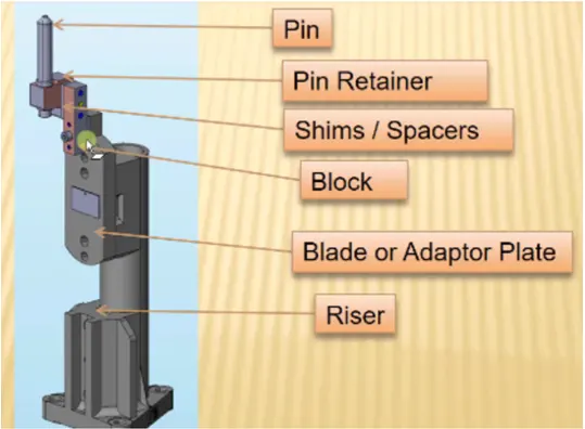
Shims for pin units are bidirectional. The complete pin unit is mounted using the block. Shims are utilized during component assembly to prevent stack-up tolerance. Shims are sold in packs of 1, and 5 mm.
Purpose: It is a crucial component of the fixture that is utilized to withstand the degree of freedom in translation and rotation of that specific component. The fixed pin unit's main function is to stop the panel from rotating around its own axis and to fix the panel's translation motion along the two axes.
Q13. Different parts of a fixed pin unit
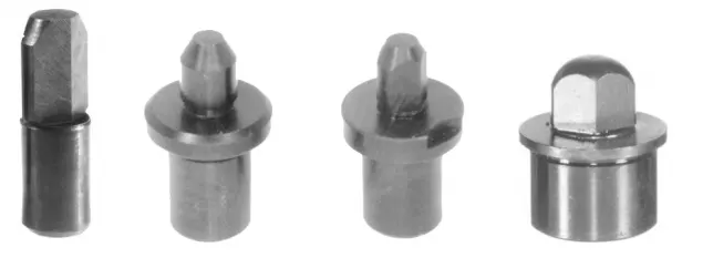
- Locating pins:
- It is utilized for precise, controlled workpiece tolerancing. In most cases, two locating pins are sufficient to accurately locate the workpiece.
- Each component needs two holes drilled opposite of one another. After installing a cylindrical locating pin, the components are perfectly aligned.
- A locating pin might be an excellent method to tighten up our assembly if we have some misalignment problems while utilizing only bolts or other fasteners.
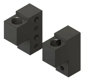
- Pin retainer: It is used to support the pin and make sure it is not moving.
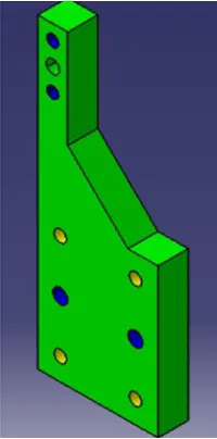
- Blade/Adapter plate: It is a plate that is fastened to the riser; on the blade, components like cylinders, arms, and other things are fixed.
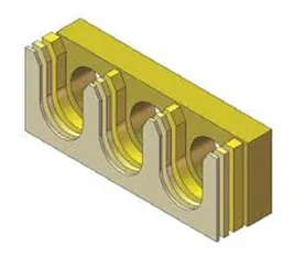
- Shims/Spacers: Shims are used in the fabrication of jigs and fixtures to close gaps and account for production tolerances. They are mostly utilized in the automotive and aerospace industries for altering the clamping points on tools and fixtures. One or more components are fixed with the aid of a clamping point.
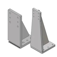
- Riser: The toggle clamp, rest clamp, mylars, and location pin are mounted to it.
- It is not required to put all the clamp, rest, or location unit components on one riser. These are often produced such that the assembly has height.
- Typically, risers are manufactured from a single gas-cut plate, plate fabrication, plate and tube welding
- Screws and nut for mechanical joining
Q14. Purpose of making a Rest unit & describe its parts
- The rest unit, which uses a Mylar/NC block to support the automobile panel, rests the panel alone; no force is transmitted to the upper clamp. Because there are fewer pieces to design and its primary function is to support the automobile panel.
- It can be used in conjunction with a clamp device to rest and clamp a panel. It can be used in conjunction with a locating unit to both locate and rest the automobile panel. Additionally, locating, clamping, and testing units can be integrated into one.
- It is not connected to a cylinder. It has a riser, a blade, and a rest mylar. Below are several rest unit components. Additionally, there are three types of rest units: basic, multiple support, and retractable.
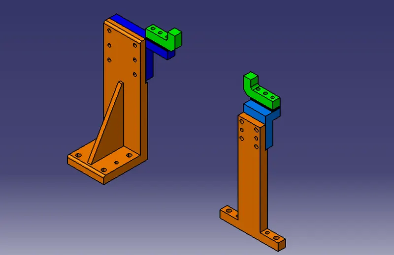
Parts of a Rest Unit
Nc Blocks / Mylars: The components holding the panel from the top and bottom are mylars. It is of the jaw kind and will not shift from its position during welding. It also known as fingers. It prevents the component from deforming as a result of welding forces.
There are two types of mylars: Clamping mylars and Resting mylars
Only resting mylars are seen in the resting unit. Resting Mylars refers to the panel that is positioned on the component.
Spacers: are used in the fabrication of jigs and fixtures to close gaps and account for production tolerances.
Blade: It is a plate that is fastened to the riser; on the blade, components like arms, and other things are fixed.
Riser: Rest clamp, mylars are mounted to it. Typically, risers are manufactured from a single gas-cut plate, plate fabrication, plate and tube welding
Q15. Fundamentals to design a Sensor unit
It is an apparatus that gathers physical input from its surroundings and transforms it into information that either a human or a machine can understand. Some sensors are simpler, such a glass thermometer that displays visual data, but most sensors are electronic (the data is turned into electronic data). Sensors are used by people to measure temperature, determine distance, identify smoke, control pressure.
Types of sensors:
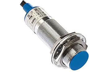
- Proximity sensors: When a target enters the field of a proximity sensor, a non-contact sensor, the target's presence is detected. Depending on the type of proximity sensor, the sensor may detect a target via sound, light, infrared radiation (I.R), or electromagnetic fields. Phones, recycling bins, self-driving vehicles, anti-aircraft systems, and production processes all employ proximity sensors. There are several varieties of proximity sensors, and they all detect targets differently. The inductive proximity sensor and the capacitive proximity sensor are the two types of proximity sensors that are most frequently utilized.
- Due to the inductive proximity sensor's usage of an electromagnetic field, it can only detect targets made of metal. The inductive characteristics of a metal target that enters an electromagnetic field cause the field's properties to change, alerting a proximity sensor to the presence of a metallic target. Depending on how inductive the metal is, the target can be detected at a greater or smaller distance.
- On the other hand, metallic objects are not the only ones that capacitive proximity sensors can detect. These proximity sensors can detect anything that can conduct an electrical charge. Liquid level sensing frequently makes use of capacitive sensors.
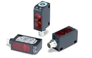
- Photo electric sensors: Through a range of optical qualities, photoelectric sensors may detect objects, changes in surface conditions, and other things. An emitter for generating light and a receiver for receiving light make up most of a photoelectric sensor. The amount of light that reaches the receiver changes when emitted light is stopped or reflected by the detecting item. This change is picked up by the receiver, which transforms it into an electrical output. Most photoelectric sensors use infrared or visible light as their light source.
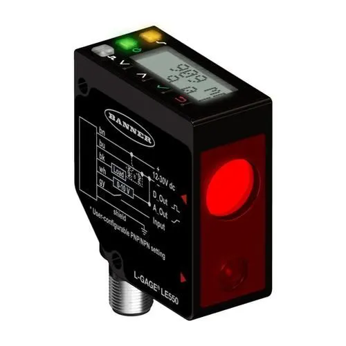
- Laser sensors: Distances to objects and the associated metrics (displacements, location, surface profiles, and velocities) can be measured using laser sensors. Several diverse optical methods, including triangulation, time-of-flight, confocal, and interferometric sensors, constitute the foundation of laser sensors. Laser sensors are increasingly employed in robotics, surveillance, autonomous driving, and biomedical fields, in addition to conventional manufacturing sector applications. These laser distance sensors gauge a distance to a target item using a focused, coherent light.
Basic principles of sensor design
- Every panel that is being welded in a tool must be detected.
- Depending on the size of the panel, one or two sensors should sense it. It is preferable for the sensors to be at the diagonal ends of the panel.
- If a component is very tiny, only one sensor is required to identify it;
- If the panel is large, we will perceive it with two sensors facing opposite directions.
- Therefore, every sensor should generally be positioned in three directions.
- Manufacturers of sensors include OMRON, IFM, and Peperl-Fuchs.
Q16. Basic fundamentals to design a Rough locator unit
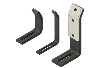
To ensure an error-free assembly, rough locators are tools that help the operator guide the automobile panels as they are loaded into the fixture. Due to the rough locator part's inability to be identified in the proper place, it is employed as a fool-proofing approach. Since the rough locators are configured for each panel, only certain loading directions and orientations are permitted.
Design principles:
- The perimeter of the automobile panel that it needs to guide should have enough locators positioned there.
- A rough locator must be positioned at a minimum distance of 2.5 mm from the edge of the automobile part, at the same angle.
- The panel should be led towards the direction of pin arresting by rough locator.
- Before the pin engagement begins, the panel should be guided by a rough locator by 10-15 mm.
- The entrance angle for the automobile panel should be considered while designing the rough locator; typically, it is between 30-45 degrees.
- To mount the simple adjustments, the rough locator should be constructed with two slots.
- The locators should be towards the car's section leading direction.
Q17. Base unit and it's parts
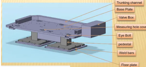
It is a unit made to hold all other units of the tool, such as clamp units, pin units, rest units, etc. Other elements, such as pneumatic valve boxes and trunk cable paths, will also be installed on the base unit.
- Valve box: All the pneumatic cylinders installed in the fixture are supplied with air via this box. It is a device that has numerous additional solenoid valves attached to it. As a result, it only has one inlet and one outlet. All the additional solenoid valves are connected to this one inlet, and each solenoid valve has inputs that are supplied to a separate cylinder before receiving outputs that are then collected and returned to the valve box.
- Trunking channel: Trunking channel is a type of cable duct that aids in directing and safeguarding the wire and tubes used in fixtures.
- Measuring hole cover: On the base unit, there are coverings for the measurement holes.
- Eye bolt: It is used to move and drag the entire unit.
- Pedestal: The entire unit is raised using it.
- Floor plates: It is used to attach the whole base to the floor and flatten the fixture.
Q18. Dump Unit and its functions
When positioning the panel, it is employed when there are any geometrical restrictions. It has a dump cylinder for clamping and unclamping purposes.
It can execute clamping and unclamping with more than one cylinder.
The purpose of dump units
It is necessary when there are any geometrical restrictions while installing the panel. Here, the first cylinder discharges the assembly containing the clamp mylars and pins, and this assembly subsequently performs the necessary action. In this unit, we must ensure that the panel may be removed when it is in the open position.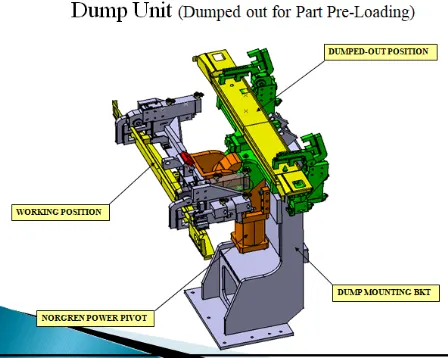
Q19. Slide unit
Slide units serve as positioning tools, moving the fixture, welding gun, units, and robot into the proper position for subsequent operations.
LM Guides, Linear Cylinder, Front and Rear Stoppers, Front and Rear Shock Absorbers, Two Proximity Switches / Reed Switches (for detecting the two end locations), Bellows, and protection (covers for rails) are the components of slide units.
- The type of guideways utilized to further categorize them into two groups is
1) A strengthened guideway.
2) LM guide way.
- Based on the sort of primary mover employed, they are divided into three categories: Manual slide, pneumatic/hydraulic slide, CNC Slides
- These are classified into three categories based on their orientation.
1) Slide horizontally.
2) Sliding vertically.
3) Slide with an angle.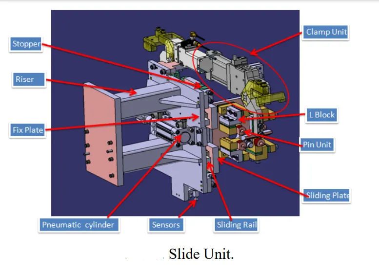
Design Considerations:
- For sliding unit applications, center trunnion/rear clevis mounted cylinders are excellent as they allow for some float to absorb misalignment.
- Due to their lower coefficient of friction, LM guideways are chosen over Hardened guideways.
- Standard LM guide rail length should be more than the actual stroke.
- Consider mechanical hard stops for both extended and retracted conditions.
- To decrease the impact load, a shock absorber should be employed in both the extended and retracted positions.
- The proximity switch will be used to detect the two end limits outside.
- At mid-stroke or within +/- 5 degrees, the shock absorber should be placed such that it is perpendicular to the pivot.
- A bellow or sheet metal cover should always be placed over the LM rails to shield them from dust and weld spatter.
- The design will be examined for screw accessibility, simplicity of assembly, and part machinability.
- Depending on the customer's needs and the brand of LM guide, LM guide and rail can be bought individually or as a single package.
Uses:
- Slide units are typically found in complicated fixtures where a sliding mechanism is used.
- When placing the panel, there may be certain space restrictions.
- For welding, slide application will be simple.
- By using a sliding unit rather than a welding robot to move the weld gun from one welding site to another, the cost of the robot may be reduced.