Week 3:- BiW Fixture Design Methodologies Challenges
1. What is Design Methodology?
Design methodology is actually steps decided during concept designing stages of a fixture design.
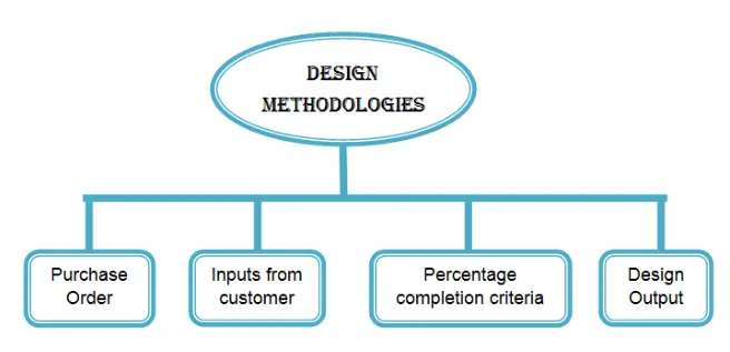
It involves foloowong steps-
1. Purhcase Order- Its actually confirmation from customer to start the design of fixture.
2. Input From customer- Its a major data for designing a fixture as per customer's requirement.
It includes-
- Functional Requirement
- Preffered standards compomnents by customer
- Car products it includes 2 D , 3 D files, GDNT, Principal Locating Points etc.
- Layout - Entire Assembly line, space data for fixture.
- Ergo data - if fixture is to operated manually, ergo data is required for fixture desgn.
- Weld Study- it includes weld gun details, weld matrix and weld point data, type of welding required etc.
- Standard Detailing Templets- These are customers standards they follow for detailing the parts. It may include naming, method of dimensioning, GDNT preferred, structure of tree.
3. percentage Percentge Criterion- It is a detail schedule of fdsign completion.
4. Design Output - It invlve lot of documentations. It includes 2D and 3 D data, BOM, Layout, Key layout sheet etc. while submeeting design to customer.
2. What are the inputs required from the customer to start designing a Fixture?
Input From customer required - Its a major data for designing a fixture as per customer's requirement.
It includes-
- Functional Requirement of fixture, more details about welding fixture, gluing fixture, hemming fixture. etc
- Preffered standards compomnents by customer- if they are using any such STD components.
Various standards are there like ABB, NAAMS, DESTACO, TUNKERS etc standard are generally used in various units.
One or two standards are used at t time. we need to follow the same while detailing and designng.
As far as possible STD parts shoild be used in an assembly.
We need not to detail a STD part. It saves a lot of time.
STD components-
- Car products it includes 2 D , 3 D CAD files pf car parts, GDNT, Part List, Clamp Plan, Product Assembly Proces sheet.
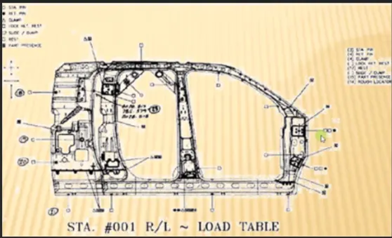
- GDNT- This data from customer provide information regarding locating pins, rest unit, clamp unit, slide and dump unit.
- It also give sequence and information of clamp onening and closing data, stroke details of slide and dump unit.
Part Lisrt- It include about all details about the parts. It includes Part Name, Part NUmber, it Revesion, thikness so that for starting this data one can decide further processand eqipments required to design.
CLAPM PLAN- It provide data of exact location of pins, rest, dump etc.
These positions are critical to maintain. If it is necessary to shifat any weld or clamp position, it shoil always be clarified.
- Layout - Entire Assembly line to understand the process, levels and available space data for fixture.
- Ergo data - if fixture is to operated manually, ergo data is required for fixture desgn. their standard data is required.
- Weld Study- it is an imp input from customer. It includes weld gun details, weld matrix and weld point data, type of welding required etc. Number of points , position, co-ordinate to be welded.
Product Assembly Proces sheet.-
This sheet will give a detailed plan of process. ONe have to follow the plan. It contain sequence of operations, welding details, and all.
Lay out sheet- info about the fixture placements, robot swept area entire, Plan of the lay out, space contraints.
A layout gives information about-
FLow of path,
Staion to staion distance i.e station pitch.
Robot Station-
Accesories - tool changers, tip dresser.
Subassembly Links-
Platform height-
Loading and unloading sequence of panels.
3. What is the input we get from "Car Products"?
Input from Car products includes
i) 2 D , 3 D files of the CAD model,
ii) GDNT- This data from customer provide information regarding locating pins, rest unit, clamp unit, slide and dump unit.
It also give sequence and information of clamp onening and closing data, stroke details of slide and dump unit.
Principal Locating Points etc.
iii) Part Lisrt- It include about all details about the parts. It includes Part Name, Part NUmber, it Revesion, thikness so that for starting this data one can decide further processand eqipments required to design.
iv) Clamp Plan- It provide data of exact location of pins, rest, dump etc.
These positions are critical to maintain. If it is necessary to shifat any weld or clamp position, it shoil always be clarified.
v) Product Assembly Proces sheet.-
This sheet will give a detailed plan of process. One have to follow the plan. It contain sequence of operations of sub assemblies, welding details, and all.
This same plan has to be followed.
4. What is the Clamp plan?
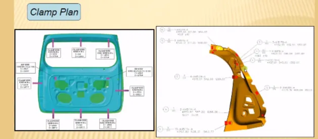
A Clamp Plan provides data of exact location of pins, rest, dump etc. on panels.
These positions are critical to maintain. If it is necessary to shifat any weld or clamp position, it shoil always be clarified.
Accuracy of the assembly is directly realted to clamp plane data.
In case in critical condition, clamp position and weld position are too close, and it is required to shift any one of them, it must be discussed with customer.
5. What is the purpose of a Layout?
Lay out - A lay out sheet provide detail info about the fixture placements, robot swept area, Plan of the lay out, space contraints.
A layout gives information about-
FLow of path of operations-
Staion to staion distance i.e station pitch.
Robot Station- available robot stations on the floor.
Accesories - tool changers, tip dresser existing to customer.
Subassembly Links- Depending of requiremnts, various sub assemblies to mail assembly lines.
Platform height- Heigh of plat form.
Loading and unloading sequence of panels- this data can be considered while desogning fixtrure.
6. What is Ergo data?
Ergonomics isstudy of human behaviour while on machines. the machine should be easy and within easy acces to the operator. it includes height of swithcs, loading and unloading of parts, frequency of operation etc. Thers should be no requiremnt of frequent bending to operator.
If it is required in manual operation type fixture, Ergo Data is required as input from customr.
For fatigue free working of an operator, STD Ergo data is to be provided by customer.
This data include, information about loading height, working safety zone fo operator so that operator should not get any sort of inconvinience to operate the fixture.
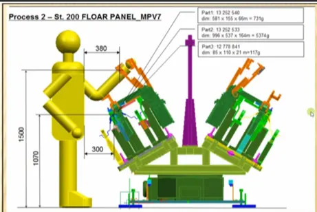
It helps to increase reuduce un-necesary efforts by operator and ultimately increases efficiency of the operator.
7. What do you understand by Weld study?
Weld study - it involves study of weld gun. as well as study of weld metrix and weld points.
There are two types of weld points-
i) Geo Weld Points- Points or spots to be welded on Geo Station.
these are represented by RED spheres.
ii) Re-spot Weld Points. - Points or spots to be welded on another pair of panels at Re-spot station.
These are represented by GREEN spheres.
The representation these weld points is known as weld matrix.
These details are provided on proces sheet.
8. What are the criteria for percentage completion in the designing stage? Explain it in detail.
It is followed in the design and dispatch stages of fixture completion.
Different Criterion for percentage completion-
0-25% - of total time should be given to Input and Concept design.
25-40%- next stage, seeking concept approval and simulation check.
40- 85%- After checking , Dsign freezing and detailing is to be complete.
85-100%- in last stage, final cheking quality and dispatch should take place. Dsign Output to customers.
9. Brief about "Output" in design.
i. It include 2D and 3D data to give to customers.
Key sheets and Layout sheet of Unitized Tools eg. pin unit, clamping unit e.t.c.
ii. Key sheet generally contains Index of units and their placements on the tool base
This data give idea about position of tools on the base unit.
iii. While a layout sheet includes all the design detail drawing of individual units to include all their components.
iv. for non unitized tools like stands, Tool Changers etc, layout sheets are provided.
10. What do you understand by structuring a design tree? How does it reduce errors during the design process?
Structuring a Design Tree:
Structuring a design tree is a process of properly sequencing of all the parts and assemblies in a fixture.
They are named in a specific way or standard and are in proper sequence.
Different customers have different set of standards to structure a design tree.
This structuring can help us to reduce errors as follow-
- It gives detail which project, tool/unit, it belongs to.
- This basically avoids errors during design study, manufacturing, assembly, inspection, etc.
- It may create confusion to understand the design & may create major possibilities of making an error, if they are not in a proper sequence.
- It can help us to identify the quantity of items of same types or different types that are being used in the assembly.
- First unit is the base unit always.
- It gives direct indication of manufacturing parts and the standard parts from their position in the tree structure.
- Structure tree helps to study or understand the parts, their repeatition in the assemblies easily.
11. What are Units? Mention 5 types of units.
Units are nothing but sets of variouns parts constructed in a fixture to perform a operation required to complete in a sequence or in specified time.
50 types of Units-
Pin Unit- To locate the panel on specified position.'
Clamp Unit- It is a unit clamping the panel.
Sensor Unit- It is sensing presence of the panel on fixture and giving signal for next operation.
Base UNit- It is base of the fixture. all other units are mounted on base unit.
Slider Unit- In case due to any restrictions on the fixture, it is not possible to perform any operation, a slider unit is provided.
It is operated by a cylinder, and frictionless guides.
ON completion of operation, slider will come baxk to its original position.
12. Describe Fixed Pin units & their purpose?
It is an important kind of fixture, which locates the panel.
accuracy of the fixture is directly depend on accuracy of the pin unit.
As it restricrs rotational dof for the component, it is required to have two directional shims.
Purpose of a Fixed Pin UNit is to locate the panels at perfect position of the fixture.
13. What are the different parts of a fixed unit?
It is a unit designed to locate a car panel.
Different parts of a Fixed Unit-
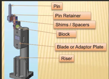
- Riser- A std part, giving heigh to the structure.
- Blade- A part supports NC block .
- Spacer (Shim)- A std part for adjusting height of fixed pin unit.
Two direction adjustment is required for pin fixed pin unit, in horizontal as wel as vertical direction.
Block- it is s aNC block to mount pin unit.
Pin Retainer- A part on which Pin rests.
Pin - A locating pin for the panel.
14.What is the purpose of making a Rest unit & describe its parts?
Purpose of a rest unit- to rest or support car panels using NC block or Mylar or Rest.
It is a simple unit.

Basic Parts-
Riser- A std part, giving heigh to the structure.
Blade- A part supports NC block .
Spacer (Shim)- A std part for adjusting height of Rest unit in vertical direction.
N C Block- acting as base or support for the panel.
15. What are the basic fundamentals to design a Sensor unit?
A Sensor Unit is ther in BIW fixture to sense the presence of panel using a sensor.
Basic Fundamentals are-
- Each individual panel shoul be sensed by the sensors
- There should be atleast 1 or 2 sensors per panel , depending upon size
- every sensor should be mounted on a 3 directional adjustable way.
16. What is a Rough locator unit & what are the basic fundamentals to consider while designing it?
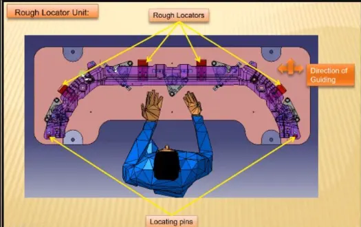
A Rough Locator in a BIW is a guide for pannel on fixture.
These locators help operator to loacte and position the pannel in correct manner.
Depending on panel shape, they are availabl ein L shaped inside, 1. L Shape Outside and I shaped Rough locators.
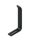
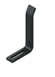
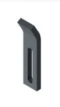
1. L shaped inside, 2. L Shape Outside 3. I shaped
Considerations for designing a rough locator-
Entry Angle of rough locator should be 30 to 45 degrees.
They should be placed at the edges of panel, in the same angle that the panel is with a distance 2 to 5 mm.
to avoid damage to panel while laoding and unlaoding.
A rough locaotr should guide 10-15 mm before the pin engangement starts.
Bottom of a rough locator should have a slot for attachmnet purpose.
Direction of slot should be same as car part guide.
17. What is a Base unit and describe it's parts?
It is a non-Unitised-SImple tool in a BIW Fixtures.
It is foundation block of a BIW fixture.
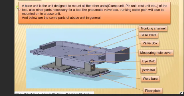
all other units like PIN UNIT, CLAMP UNIT, REST UNIT, SENSOR UNIT etc are mounted on Base UNit.
Apart from these units, other equipments necessary for the functioning of fixture are housed on the base unit. e.g. Pneumatic Valve Box.
Base Plate- Its a plae on whichall other units are mounted actually.
Its has number of holes for mounting purpose of other units.
Valve box is a unit that contain One INput and ONe putput for the air, for various pneumatic applications.
There are number of Solenoid Valves as per rwquirement for distributing air.
Also turnking channel is also on the base plate.
Eye Bolts- for relocation purppose are provided on base plate.
Base plate is connected to floor palte through weld bars. All these parts are designed as per customer's requirements.
Floo panels -
Measuring Hole Cover- These are plates with co-ordinates printed on it. Actually these are ref. poits for measuremnts to CMM. And the plate covers the co-ordinate hole to avoid its damage due to burr, dust and other imourities.
18. What is a Dump Unit and what are its functions?
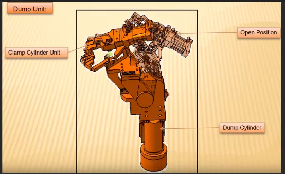
It is used in a special case. If there are any strict geometrical constraints for any units to assemble easily, a Dump Unit is the solution.
Its has a dump Cylinder and clamp cylinder unit, as per requiremnt of the process.
A pannel is assembled on the dump unit in this case and the operation is performed on the dump unit itself.
19. What is a Slide unit? Mention where Slide units are commonly used.
A Sliding Uit in a BIW fixture is generally used in BIW where space is a constriant.
or where it is not possible to position different units.
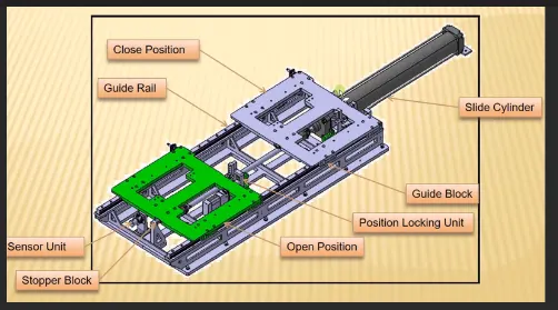
Slider units gets operated with the help of a cylinder.
Slider slides on a froction less guides, get positioned at ideal location with the help of POsition Locking Unit (OPen Position i fCylinder).
To confirm extreme position of unit, a sensor is lprovided.
aslo support block supports the slidier and resist its further movement.
Once the operatin is performmed, cylinder closes and slider come to its original position.