Week 3:- BiW Fixture Design Methodologies Challenges
1. What is Design Methodology ?
Design Methodology is nothing but the steps followed during the concept designing stages of fixture design. The key to design methodology is finding the best solution for each design situation, whether it be in industrial design, architecture or technology. Design methodology also employs basic research methods, such as analysis and testing.
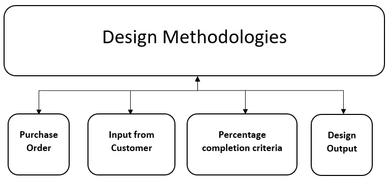
Design Methodology is divided into four parts:
- Purchase Order:
The purchase order of PO is an official document issued by a buyer comminting to pay the seller for the sale of specific product or service.
- Inputs from Customer:
Inputs that need to have with design engineer which is provided by the customer to start the project which are BOM , CAD panel data , 2D drawing of assembly , sheet metal panek thickness , spot detail , weld information , PLP , cycle time & all clamping and cylinder standards etc.
- Percentage Completion Criteria:
It consist planning of completion the project. How much days the project will take to complete.
- Design Output:
Output consist 3D models , 2D drawing which is the detailing part , BOM & other related documents. They required two types of sheet: Key sheet, Layout sheet.
2. What are the inputs required from the customer to start designing a Fixture ?
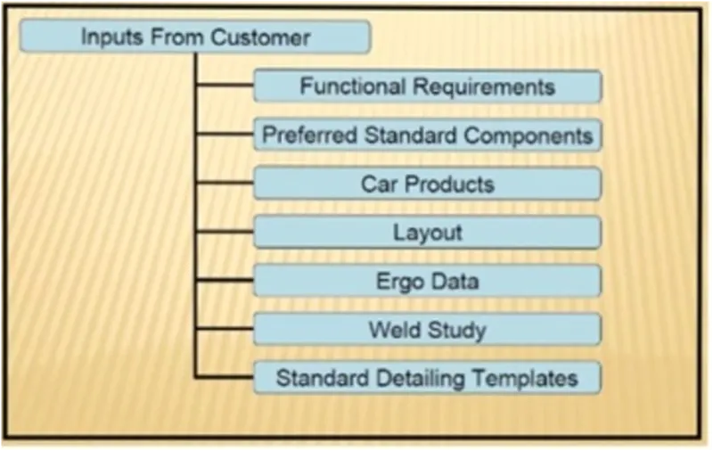
Following are the I/p from customers to start design work:
- Function Reuirement: Generally, function requirement means for what purpose we are goingto design fixture like welding, gluing or riveting fixture and inspection
- Preferred Standard Components: While designing fixture, we have to use standard components as much as possible to save time, money and efforts to design, manufacture that non-standard components.
- Car Product:
It includes following inputs from the customer.
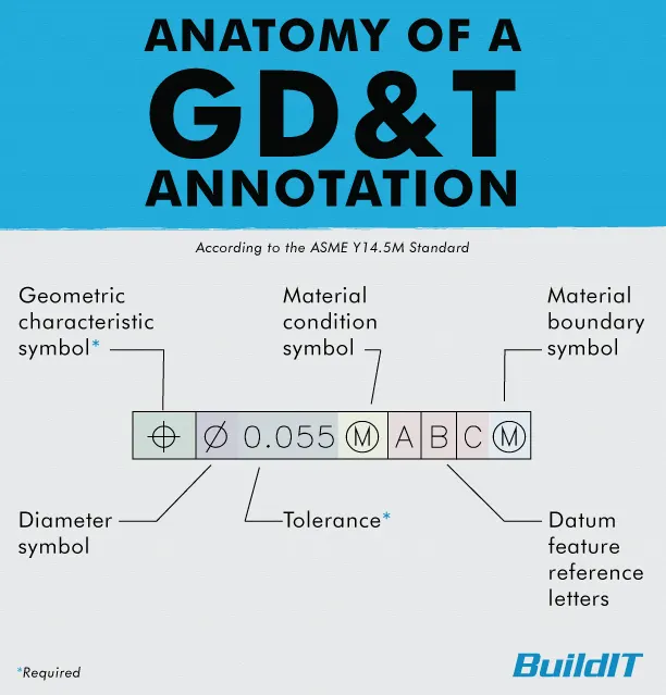
i) GD & T : Geometric dimensions & tolerencing of the parts involved in the design. GD&T provides information of locating pins , rest , clamps , dumps & slides information of each station.
ii) Part list : This is list of parts which are going to assembled in the fixture.
iii) CAD files of part: The 3D model file of the car part design by using modelling software is given from the customer.
iv) Clamp plan : This is the clamping plan of the part while doing the operation. It is very important input from the customer it provides locations of pins , rest , clamps dumps etc.
v) Product assembly process sheet : It gives detail process of completion of the part from scratch to finished product assembly.
- Layout: Layout is nothing but management of space which helps to understand process or flow of work of entire assembly line.
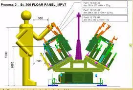
- Ergo data: Every company have standard ergo data and they provide it to fixture designer to designfixture consideringthat points height of fixture is decided according to ease while working on fixture. So, we have to design a fixture by considering safety, easy and fool proof design.
- Weld Study: In this input, customerspecify which type of welding (spot or seam) is required to join component
-
Standard detailing templates Every customer have there standard of detailing & the templated which are used for 2D drawing & detailing.
3. What is the input we get from "Car Products"?
- Following are the inputs we get from car products
- GD & T: GD&T stands for Geometrical Dimensioning and Tolerance. GD&T of each part is given in car product in which information of locating pins, clamps, rest and slides are mentioned. Image provided below shows how GD & T is apply for particular part
- Part List: It states about the parts and assembly styl Part list consist of unique part names of each and every parts in assembly and each part has its own part number which helps while assembly process to identify each and every part in assembly
-
CAD files of part: The 3D model file of the car part design by using modelling software is given from the customer.
-
Clamp plan : This is the clamping plan of the part while doing the operation. It is very important input from the customer it provides locations of pins , rest , clamps dumps etc.,
-
Product assembly process sheet : It gives detail process of completion of the part from scratch to finished product assembly.
4. What is the Clamp plan?
Clamp Plan is very important input that we get in the car products is where exactly we can place those clamping units are the particular pin Units.
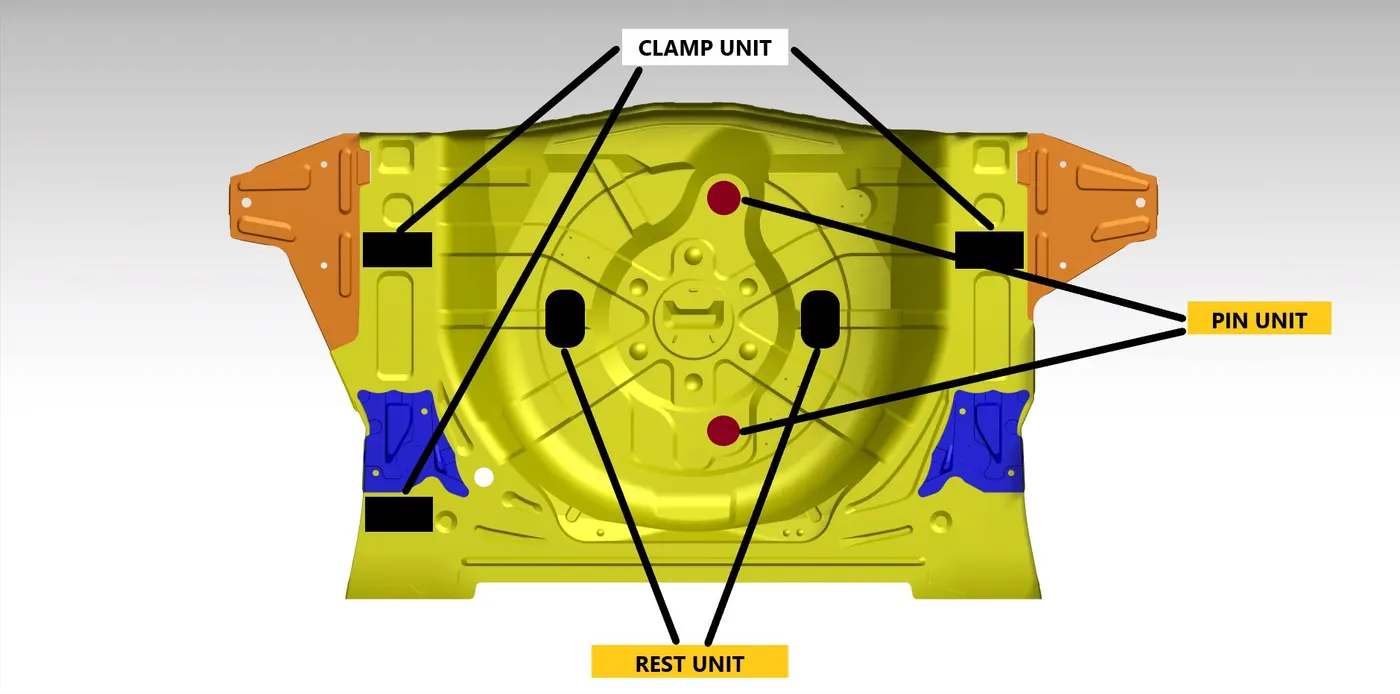
Clamps are nothing but a mechanism or component used to hold or clamp job in fixture sucurely. Clamps are manual type, hydraulic type or pneumatic type depending on customer requirement.
Clamp plan mentions or gives the location of clamps in which component is going to clamp. We can't change clamplocation without customers approval, first of all we have to take permission from customers side to change clamp location.Clamp plan also provide information regarding location of pins, rest, clamps and dumps.
5. What is the purpose of a Layout?
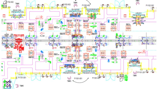
The purpose of the layout is to understand the information about where the fixture & robots are been placed, working area covered by the robot, what are the fixtures assigned for the robots to do the process, etc. layout shows the entire assembly plan to understand the process.
The swept area of the particular robot is shown by the circle surrounding the robot, which indicates the robots' reachability, notably with the confine circle.
Parts flow, station pitch, robot stations, accessories such as tool changers and tip dressers, sub assembly links, plat form height, and loading/unloading sequence/height are all provided by layout.
6.What is Ergo data ?
Ergo data is basically involved well manual operators are involved, and every company has different types of standard for aggregate data, so we'll be getting that particular input from the customer so these are the standards that we follow So,this kind of Ergo data we get from the customer.

Ergo data is basically where is given when a manual operator is required. So this import will be given in regards to how their standards of Ergo data so this is one of the standards of the country that they follow for an ERGO data so height and minimum height of the session we mentioned here, and also the distance, which is required for the operator from the fixture design except.
- So this is very important as images to the study of human behavior and moments, and your data provides information of loading height working safety zone and operation. So it also gives you the safety zone of a particular man operator. So, how much distance is supposed to be from the weld gun.
- The heights are mentioned because of the operator itself, he should not bend, while doing the operation. It was going to be a strain on his back, the height should not be way too much so that he can't even see what are the other particles because it's gonna be uncomfortable for him and his shoulders are gonna get frayed.
- So this is basically to make the operator as comfortable as possible so that he will be more efficient in doing work and he will not take a lot of time while doing the particular assembly.
- The distance from the operator and the component be 1070 is the particular component and this is the reachability 300 if it is there, and the max reachability of the particular operators is 380, so he doesn't have to stretch his arm to get that particular company, if it is 380 it's totally fine. If it is 300 that is also acceptable and 1070 particular component or particular parts location.
- The height of that particular component which is acceptable will be around is the operator's waist size, which is easily accessible for him. Again, the maximum height should be 1500, which is also easily accessible to him, and which is done.
- So this is the schematic example of how the algorithm looks like.Effective economic data or effective ergonomic friendly mixture designers, the better the efficiency of the particular operator to work on it, and the less the time consumed, so it's going to be very important factor, wherever the manual operator doesn't work.
7. What do you understand by Weld study ?
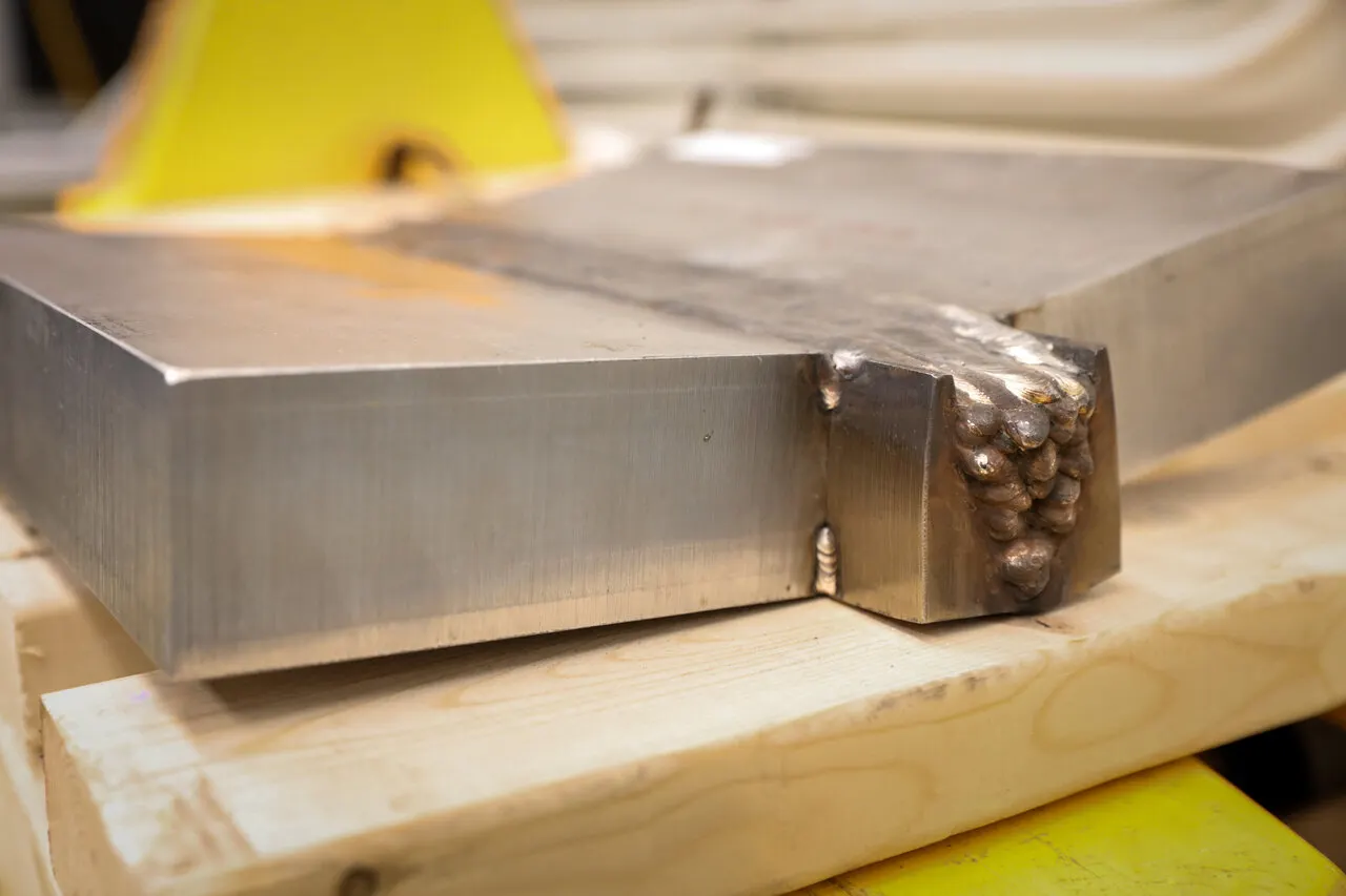
weld study means A study of the particular gun that we are going to use for welding and where we are going to weld. So if we doing a spot welding what kind of spot welding we are going to do number of welding to the particular component.
Weld Study includes
- Weld Gun Details
- Weld matrix and weld points
- Geo weld points and Respot Weld Points
- Weld Gun Details
This involves the study of the gun. So this is one of the example of weld gun, which is used in assembly. So weld study includes weld Gun detail weld matrix and weld points.
- Weld matrix and weld points
Weld points are basically where the welding is going to happen at which point at which coordinates is going to happen.
- Geo weld points and Respot Weld Points
The data of weld metrix and weld points will be given to you in the form of spears i.e Green and red Spears.
- At that points welding is going to happen.
- Geo spots are Red in Color and Re spots are Green in color.
- All the red spheres are going to happen in geostationary.
- In the respot station where the green welding is going to happen. So this is happens where one component is going to attach to this particular component, and in the other station, the other component get attach
8. What are the criteria for percentage completion in the designing stage? Explain it in detail ?
Percentage completion criteria is basically schedule. So when we are going to complete the in entire designing, then we're going to move on to simulation on all these subcategories would be considered in percentage completion cateria like a probability to when we can complete the entire fixture design.
Percentage Completion Criteria is followed in the designing stages and dispatch stages of welding fixtures.
- 0-25% Input and concept design
- 25-40% Concept approval and simulation
- 40-85% Design freezing and detailing
- 85-100% Check and Final dispatch
Input and concept designing - 0-25%
In this they given four days to design the fixtures that means we have to complete 25% of the task within four days.
Concept approval and simulation - 25-40%
The concept of design is approved here, and the simulation check is done here, which is 25 to 40% of your design is complete in Comcept approval and simulation.
Design freezing and detailing - 40-85%
In this process the design is getting Freazed. That means design is getting finalized. And the detailing is going to start again.Once the detailing is finished, and the design is also feezed that means you have completed at least 40 to 85% of task.
Check and Final dispatch - 85-100%
In this stage this is final stage,Here checking the quality check usage and the final dispatch, which is the output that we are going to give to the customer, which is from 85 to 100%
9. Brief about "Output" in design
The output of any design procedure should consists of following points:
- Design should be as simple and economical as possible.
- Design must compile all the safety and ergonoic requirements.
- Weights of the movsble parts should be minimal while maintaining maximem strength
Design output documents must define the critical outputs (specifications, properties) and reference your acceptance criteria. All of this must be documented, reviewed, and approved before the design is released. The outputs also provide needed important information for purchasing, production, and servicing.
- The design of output is the most important task of any system. During output design, developers identify the type of outputs needed, and consider the necessary output controls and prototype report layouts.
- Choosing the right output method.
- Designing Output to Serve the Intended Purpose. All output should have a purpose.
- Designing Output to Fit the User.
- Delivering the Appropriate Quantity of Output.
- Making Sure the Output Is Where It Is Needed.
- Providing the Output on Time.
- Choosing the Right Output Method.
- At the end of this phase, a logical solution is defined which is passed to the Development phase. Prototypes are also developed in this stage. Another output of the Design phase is a road map which talks about the scalability of the solution at a later stage.
10. What do you understand by structuring a design tree? How does it reduce errors during the design process
A process where all the assemblies and parts are named in a specific standard.Different customers have different set of standards and the structure of design tree.
- Every company,every customer has different standards of their own structure design tree.
- So they will be giving a template on how the structuring and detailing of the design is done. And you have to follow that particular designing or structuring of the tree.
- In the design tree itself if we mentioned that particular name, wherever that part is we can easily know that this part belongs to this zone or This station or this assembly on particular unit. So this helps us to avoid errors during the design study,manufacturing assembly and inspections.
- Structuring a design tree is actually to avoid all the errors, which might come during manufacturing assembly, or either in house inspections as well.
- If the part, or assembly are not named properly, or design tree is not structured properly, it will create confusion to understand the design and may create major possibilities of making an error.
- Every part, every component should be named according to their precedures.
- If we did a mistake or renamed the entire standard parts from the customer as a design part.Now the customer is going to manufacture the entire part again from the scratch, but he already have that product in his itinerary.but extra cost,extra time and not feasible.this is also known as an error which is actually going to increase the cost of the entire assembly as well.
- Naming a fixture or a unit or a part gives the information as to which project zone or assembly do they belong.
- If we name the part properly or name the fixture properly it'll actually tell which unit or which assembly or which zone or in which station it actually belongs.
- It can help us to identify the quantity of items of same types or different types that are being used in an assembly.
11. What are Units? Mention 5 types of units
In general , units is a device that has a specified function, especially one forming part of a complex mechanism. A welding fixtures is a assembly of different types of units.
- The BIW fixture is assembly of different units which are designed to fullfill different purpose.
- The unit have specified function like resting the panel , clamping the part , locating the part etc.
- According to the 3-2-1 principle of fixture design the units are designed to locate & clamp the car panel to its specified position in fixture while operation is going on.
n units they are two types one is unitized tools and non unitized tools.
UNITIZED TOOLS
Unitize tools are basically tools which are a part of multiple units or multiple tools inside of it
These are the tools which has to be represented by two formats key sheet and layout sheets.
unitized tools are basically two types,
1.Simple units and
2.Complex units.
NON UNITIZED TOOLS
non unitized tools are basically one unit itself, which is basically don't have any process functionality to it is just to keep component on it as a stable, like grippers turntable stands, etc.
1.Simple Units
Simple unit will have a very simple design to it, then the approach of the designing and manufacturing is also will be very simplistic like rest unit.
- Rest Unit
- Fixed Pin Unit
- Retract Pin Unit
- Rough Locator Unit
- Sensor Unit
- Base Unit
2.Complex Units
Complex unit, like slide unit as an example of a complex units that design in itself a little complex in design.
- Slide Unit
- Dump Unit
12. Describe Fixed Pin units & their purpose
Fixed pin unit is a unit designed to locate the car panel using pins.
Pin unit is used to lock the rotational position of panel. Round Pin is used to control panel in two directions while Diamond Pin is used to control panel in one direction. A pin unit in which pin’s position is fix, is called Fixed Pin Unit.
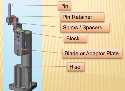
Fixed pin unit is a unit designed to locate the car panels using pins.
The fixed pin unit is part of 3-2-1 principle , it restricts 6 degree of freedom of a car panel.
13. What are the different parts of a fixed unit ?
Fixed unit consists of
- Pin
ypically, locating pins are used for controlled, fine tolerance positioning of a work piece. For example, a pallet that is moved along one axis, where the drive mechanism is not accurate and stable enough to place it in a position sufficiently accurate to execute a particular process, the use of locating pins may be the best solution.
Usually two locating pins are enough to properly locate the work piece on one plane.
- Pin retainer
It will support the pin.
- Shims
Shim is a set of thin plates (2 mm, 1mm, 0.5 mm, 0.25mm) that are used to adjust the gap or used for a better fit. Shimming can be of thickness 5mm, 8mm, or 10mm. in case no proper fitting between mylar and Panel due to manufacturing errors then this error can be removed using shims. Shims are placed in the carline position so that gap can be adjusted in the required direction like X, Y, or Z.
- Blade or adaptor plate
The plate which connects Riser to the Clamp cylinder is named Blade. This plate plays an important role in building the unit. The plate can be of any shape. But we need to keep in mind that the plate should be as compact as possible.
- Riser.
Riser is a structure generally used to mount the toggle clamp and rest, clamp mylars and location pin. It is not necessary to have one riser where all the parts of clamp or rest or location units are mounted. Generally risers are either made of plate fabrication or plate and tube welding together or from single gas cut plate.
14. What is the purpose of making a Rest unit & describe its parts ?
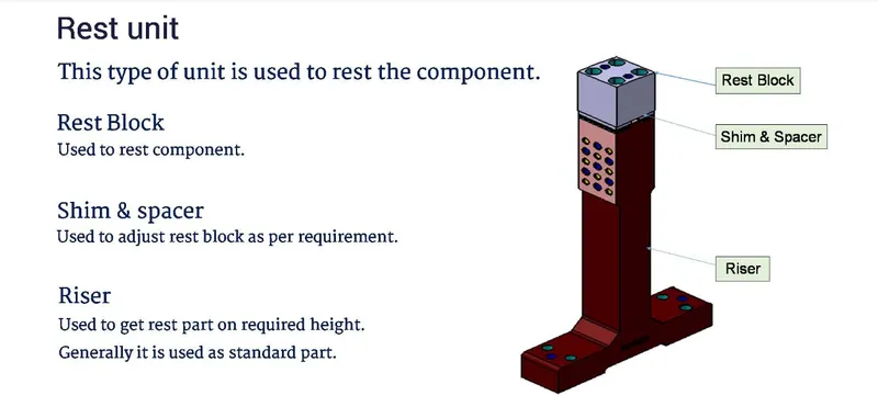
The primary devices used for holding a workpiece are clamps/Clamp unit. Resting: The car panel will rests on the rest unit, Also it resists the clamping force of the finger & thus clamp the car panel
15. What are the basic fundamentals to design a Sensor unit ?
Sensor unit is a unit designed to sense the car panel by using electrical sensors, the signal from the sensor will fed to a PLC which is our programmable logic controller and sort of the next process will be executed by this signal.
16. What is a Rough locator unit & what are the basic fundamentals to consider while designing it ?
Rough locator is a part which is designed to guide the operator to locate the car panel on the pin accordingly rough locator can be of standard parts or make part.
The locators are used in loading and unloading the pan. These are very handy while orienting the part properly, so it will actually guide the entire the operator to load the panel in a particular orientation.
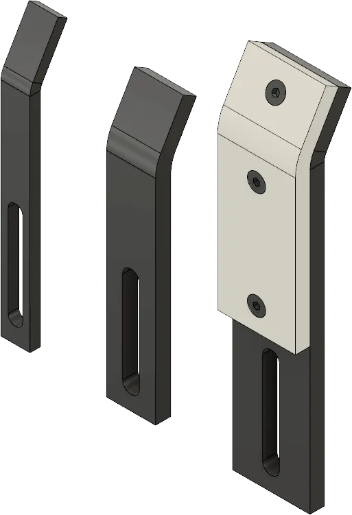
The basic fundamental to consider while designing :
- Rough locators should be placed at edges of the car panel which has to guide.
- Rough locators should be placed at the same angle of the car panel edge with min. distance of 2-5 mm from the edge of the car panel.
- Rough locators should guide the panels in pin assembly direction in general.
- The slot should be in direction of car part only.
17. What is a Base unit and describe it's parts ?
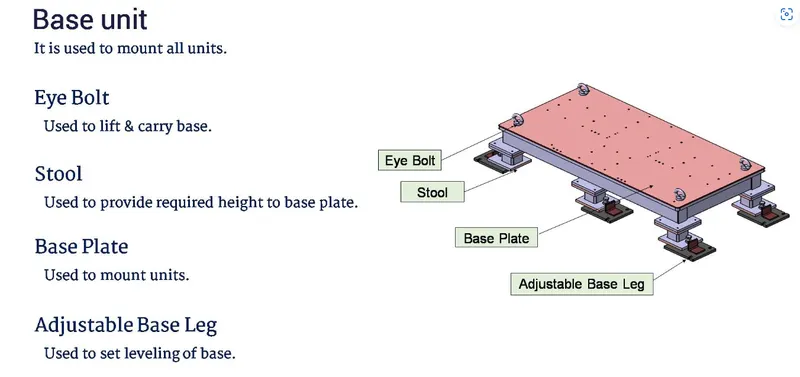
A base unit is the unit designed to mount all the other units(Clamp unit, Pin unit, rest unit etc.) of the tool, also other parts necessary for a tool like pneumatic valve box, trunking cable path will also be mounted on to a base unit.
The parts of the Base unit are mentioned in the below figure.
18. What is a Dump Unit and what are its functions ?
A dump unit is a unit where you actually assemble a component which if you have certain constraints
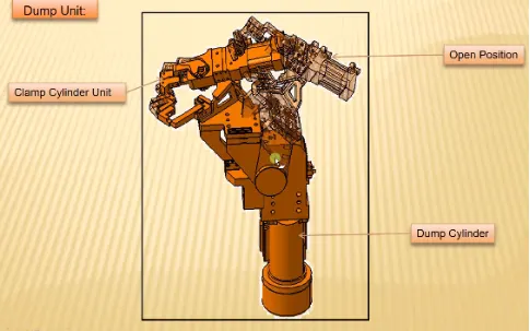
Function of dump unit :
To ensure proper resting of the panel being welded and to restrict its motion. To ensure there are is no rotation in the panel and to fix it either by pins or side blocks or magnets.
19. What is a Slide unit? Mention where Slide units are commonly used.
Slide units are positioning units , which are used to position of the car part or panel units weld gun , slots for further operations.
Sliding units are basically used in places where you have a lot of constraints or space constraints, when you cannot use different types of units to design the entire assembly.
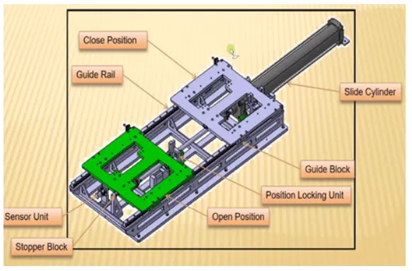
Slide units may be classified into two types :
1. Handed guideway.
2. LM guideway.
- Slide units may be further classified into three types based on prime movers :
1. Manual slides
2. Hydraulic / pneumatic slides.
3. CNC slides
- It may also classified depending on applications :
1. Horizontal slide unit.
2. Vertical slide unit.
3. Angular slide unit.