Week 3 - 2D meshing for sheet metal
AIM: To Perform a preprocessing operation on a given hood model using ANSA.
OBJECTIVE:
1) To check the given geometry for errors and to clean up the errors as requirements.
2) To extract the Mid Surface from all the components.
3) To set the quality parameter and to Mesh element Parameters.
4) To Perform 2D a Meshing Operation on a surface as per given quality Criteria.
5) To assign the thickness to all components.
To Import Given CAD Model:
In the ANSA software, import the required Hood file using the File>Open option. Below Hood model will appear in the software The Hood model consists of five components which are inner Panel, Outer Panel, one Latch Reinforcement, Two Hinge Reinforcement
PID of individual parts to seiect required geometry:-
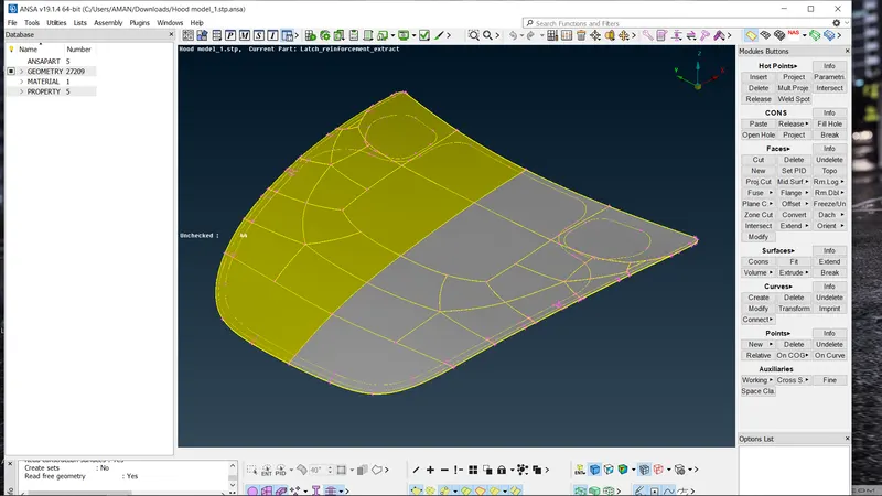
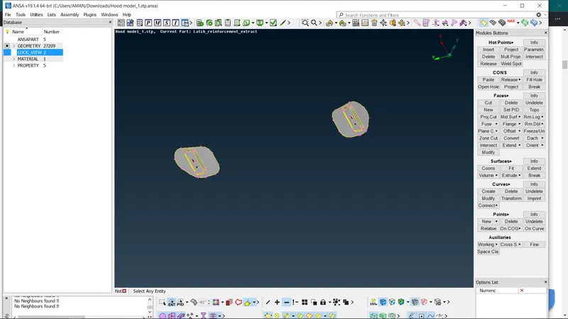
Now, we can see that there are 5 geometries in this stp file. We can see that by using their property ID. So turn on the PID mode to see geometries of different colour and we can on or off them using the PID option. We can separate all different parts for our convenience using properties right click>show only in Entity mode.
1 outer panel
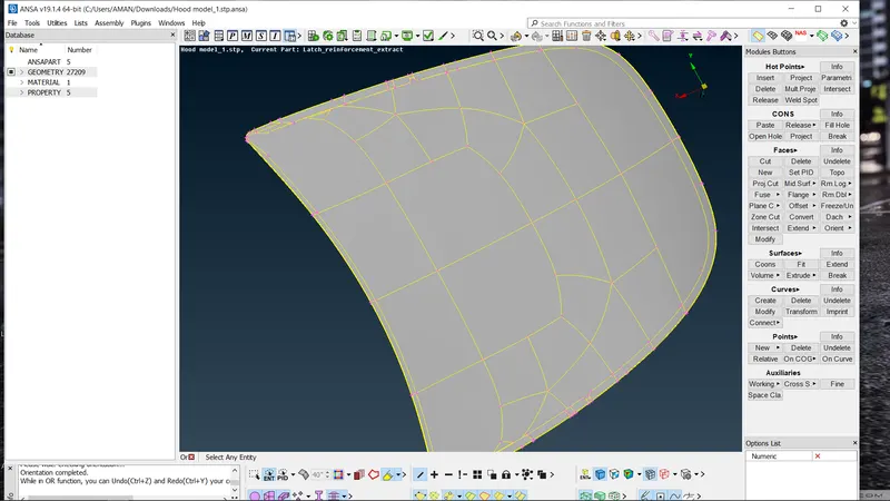
2 inner panel
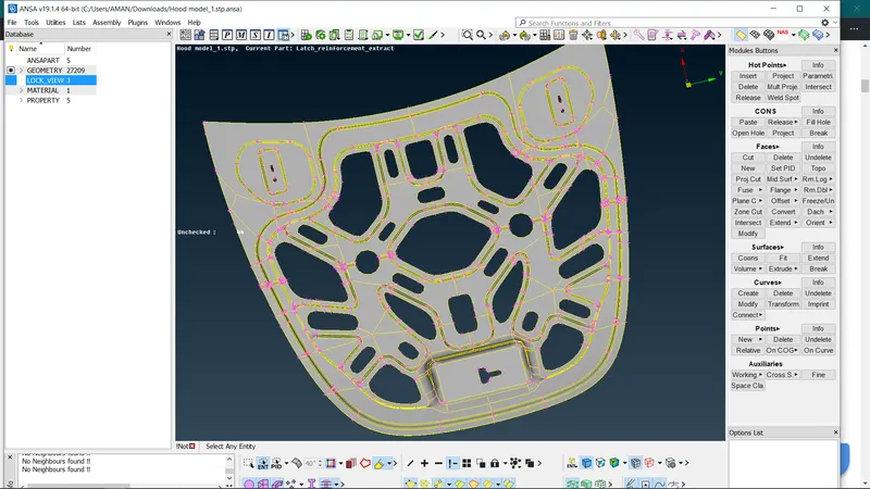
3 Lacth
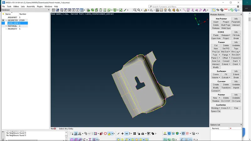
4 Hinge
The Orientation of the surface:-
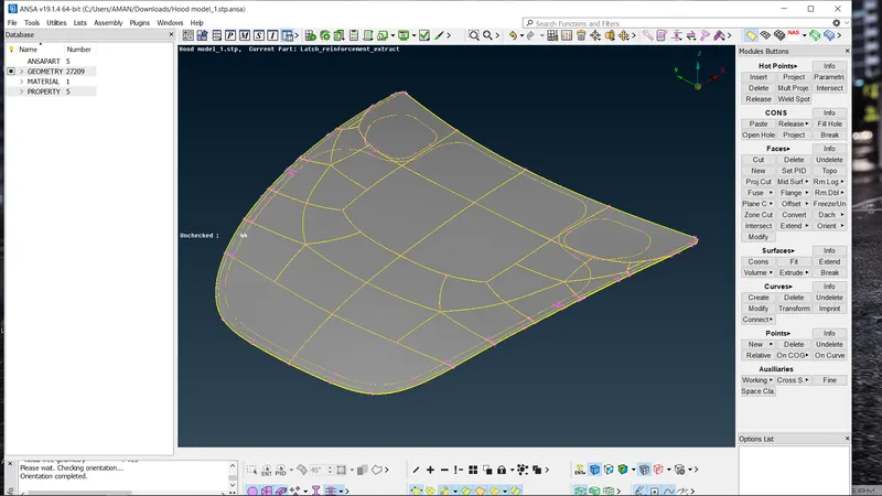
In entity mode, we can see that the component is not perfectly onented as its show yellow and grey colour surfaces on the same side of the surfaces. In order to orient it on the same side (positive or negative) we have to use the Faces>Orient command and select the side which has to orient.
Geometry cleanup:-
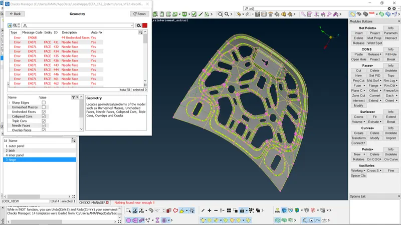
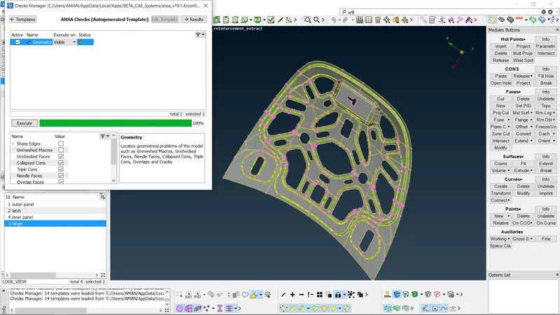
Imported cad design can be seen as normal at first, but there will lot of errors like extra surfaces, lines, points that are hidden in the cad file which is difficult to identify by just overlooking it. So we have to fix it before proceeding further cause later on it could affect the meshing quality of component and final analysis. So geometry cleanup is necessary in order to perform the FEA analysis further. Geometry check is performed by going to Checks>Geometry. Click on Execute as in the below image. The other image shows the errors detected.
Mid surface skin generation:-
The mid surface is the neutral phase which is to be generated from the given components of the CAD model Here we convert basically 3D to 2D model. The mid surface is generated to reduce the complexity by simplifying the cad model to get more accurate simulation results in a shorter duration. Here i am using automatic nid surface generation which is done by Faces>Mid. Surface option/command to save tirme and to get perfect mid with automatic ID generation. Otherwise one can take offset of the component to get the mid surface of compent. Before mid surface generation, measure the thickness of the parent geometry which is to be used The thickness should be measured at various points/places To measure the thickness, use the measure option
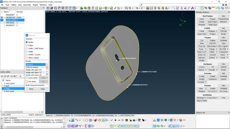
Manual - offset:
In Topo module, Faces > click Offset for manual skin generation & select faces and do middle click. Enter the offset value which will be half of the thickness value of parent geometry that we have measured before. The value sign (-/-) can be given as an orientation view. In manual skin generation, PID should assign manually by going to Faces Set PID and assign all the properties asa requirement.
Auto - skin:-
in Topo module Faces > click Mid surface Skin for auto skin generation & select the entire component & middle click Then the edit area tab will open. Now check Red color for the bottom surface. Green color-top surface, Blue color for the middle which is basically the thíckness of the component. If the surface is able to generate then do the middle click on the mouse. If not, correct the colors by using the edit area tab. Here the offset value should be positive only. In auto skin generation. PID will assign automatically.
Quality Criteria:
To enter the given quality criteria values given in the probiem, Go to Utilities quality criteria/press F11. Enter the given values by checking the box accordingly. Save the quality criteria value and import it white reopening the CAD file.
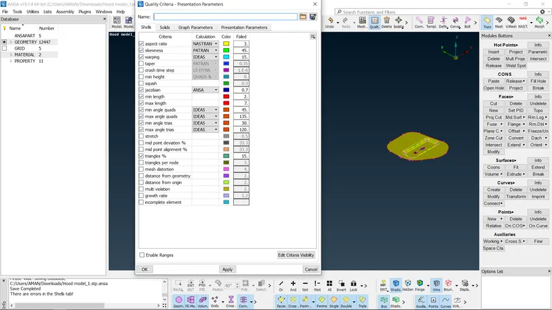
Meshing-
Now go to Mesh from the Topo module. Click on Perimeters Length.
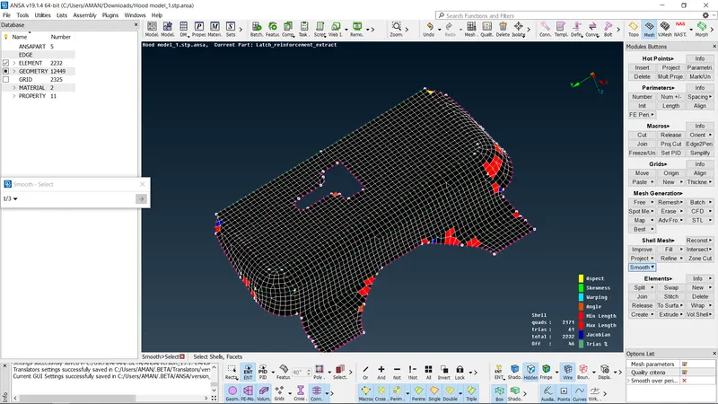
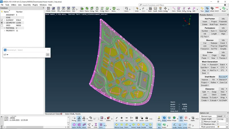
Seiect the component and assign the length of 5 for meshing. Next, for meshing Go to the Mesh generation Best. This option generates the mesh using the best algorithm applicable. Then, the created mesh is refined using the Shell Mesh>Reconstruct. Trias are kept as low as possible wnije meshing. While removing the triais, the some following things need to be considered.
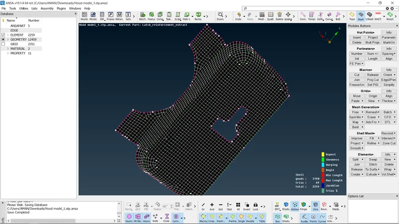
Elements Split -
to split an element and move tria forward Elements>Join - to join two trias to make a quad Grid Paste - to paste the nodes and move tria backward Elements Swap - to move the tria left or right
I have used Shell Mesh>Reshape command also to remove trias.
After modifying the mesh, Shell Mesh>Smooth command is used to smoothen the flow of the mesh. Any elements failing for qualitycriteria are also fixed by either reconstructing and smoothing the elements.
CONCLUSION:-
CAD model importing. Geometry cleanup, mid-surface extraction, measuring thickness, 2D meshing. giving thickness of the given hood model with the given element Quality criteria were successfully done No off elements are there presented and passed the quality criteria. All the features in the model are captured properly with good mesh flow. Tria concentration is kept at a low percentage