Week 2 To perform a static structural analysis on the Railwheel and Track setup of different bearing load using ANSYS.
OBJECTIVE:- To perform a static structural analysis on the Railwheel and Track setup of different bearing load using ANSYS.
Case 1: Multiply the bearing load by 5 times and compare the results with the load of 100000 N. Compare the Total Deformation, Equivalent stress and the life under both the loads.
PROCEDURE:-
FOR 100000 N Bearing Load:-
- Open Ansys Workbench and choose static structural.
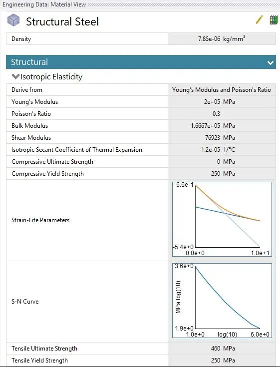
- In the Engineering data, let the material be structural steel with default values.
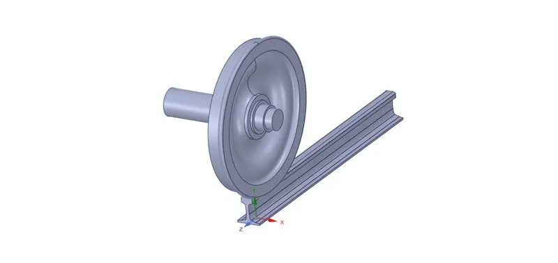
- For the geometry, right-click and import the given Railwheel_Track.x_t and open the space claim to check it.
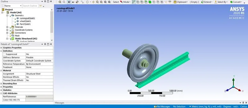
- Now in the workbench goto Model -> Edit, in the model window check the Geometry for the material and assign Structural Steel to all the part.
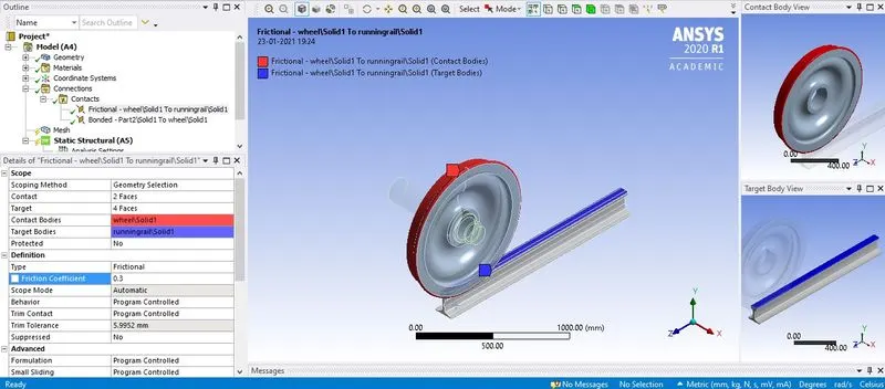
- Now for contact, flip all the contact and target, for wheel and track type= Frictional and friction coefficient= 0.3 and for wheel and shaft type= frictionless.
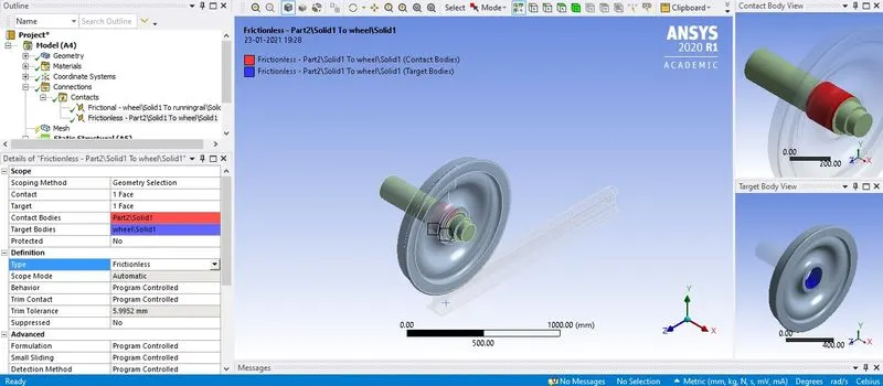
- For joint connection, there are 3 types of joints that have to provided, for track fixed joint, for shaft translational joint (also change the reference axis as the translational is along the x-axis but x-axis is facing perpendicular to the wheel it should be along the track) and for wheel planar joint.
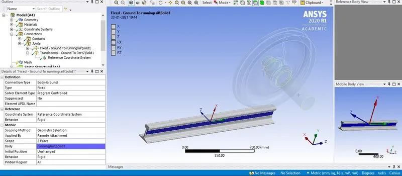
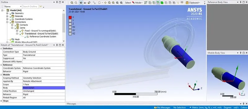
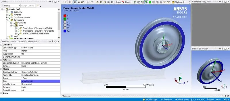
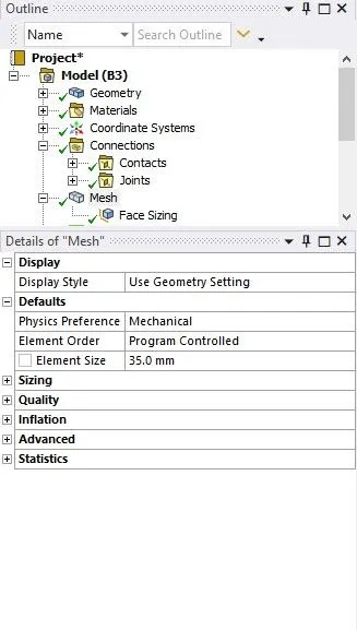
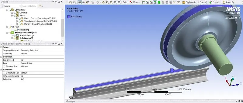
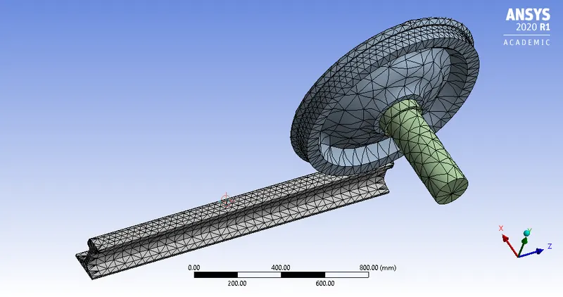
- For mesh, element size= 35mm and also mesh the area of interest of the wheel and track by element size= 35mm by selecting mesh -> insert -> sizing. Click on generate mesh to mesh the wheel, track and shaft.
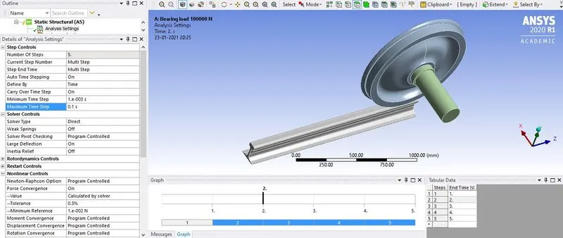
- Now for the analysis settings, the number of steps would be 5 from that for the 1st step only the Auto time stepping= program-controlled and for time step 2 to 5 the Auto Time Stepping= On, Define by= Time, Carryover time step= on, Min. time step= 0.001s and Max. time step= 0.1s and for both types of time step the Solver type= Direct, Force Convergence= On, Turn on all the setting for the Output controls.
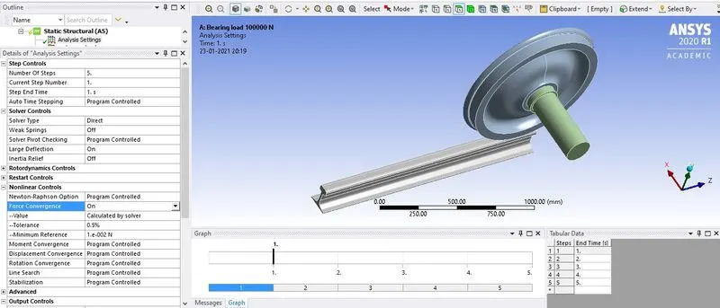
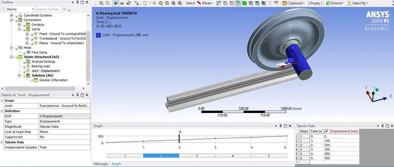
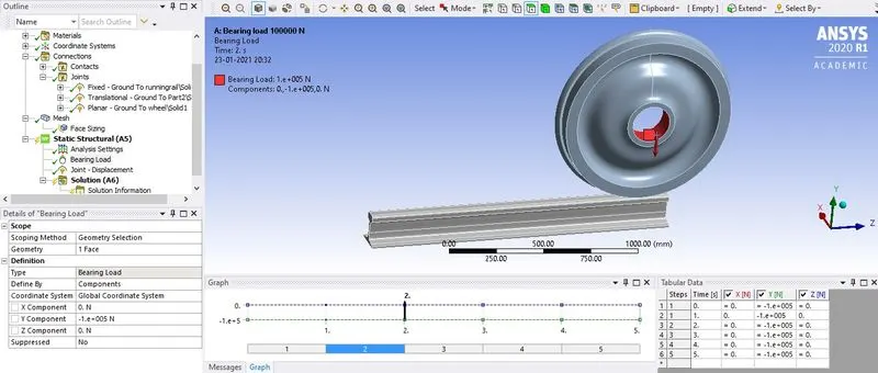
- Now to apply the load, joint load where Joint= translational, Type= Displacement, Magnitude= tabular data, provide displacement value 0 to 500 in an interval of 100 to the 5 steps and bearing load where Geometry= shafts meet the wheel, Define by= Component, In Y Component= -100000 N for all the steps.
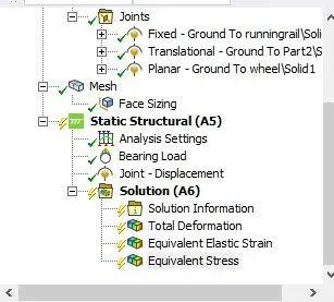
- Provide the required output request for the solution like total deformation, Von-Mises stress and Equivalent elastic strain and click on solve.
For 500000 N Bearing Load-
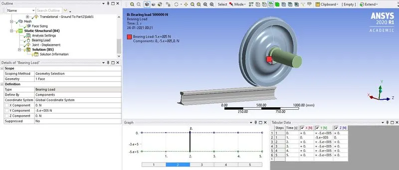
- All of the settings applied for the 100000 N bearing will be similar only in the Static structural setting Bearing load will be 500000 N (-ve as to apply downwards of the Y component) for all the 5-time step.
RESULT:-
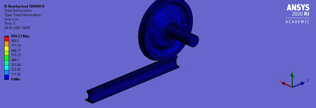
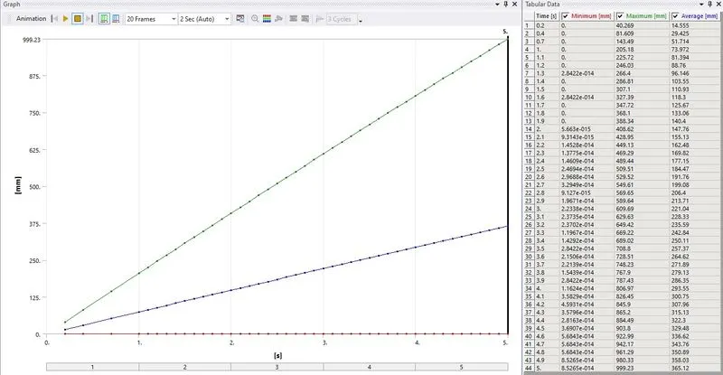
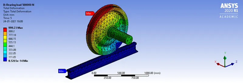
Total Deformation
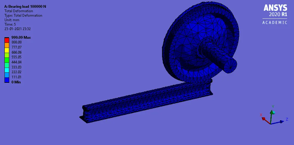
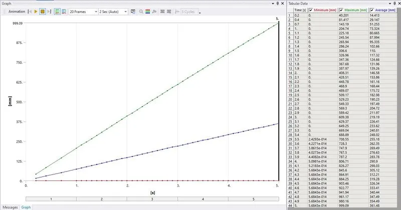
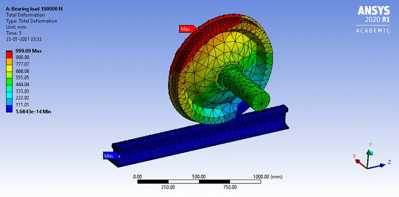
For 100000 N Bearing Load
For 500000 N Bearing Load
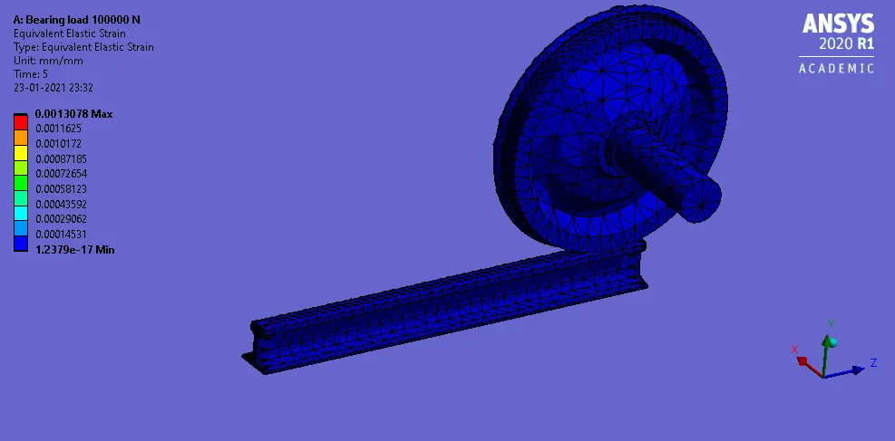
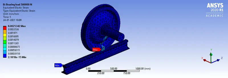
Equivalent Elastic Strain
For 100000 N Bearing Load
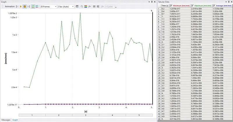
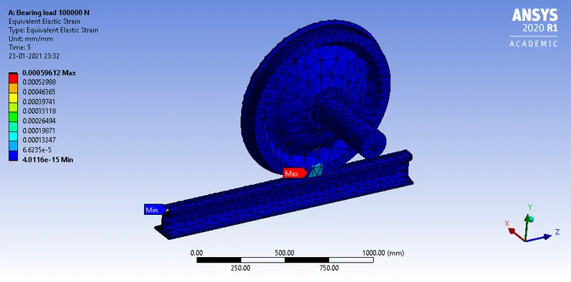
For 500000 N Bearing Load
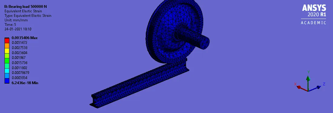
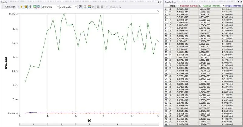
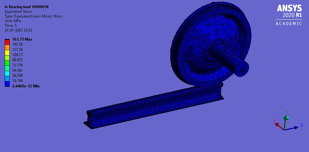
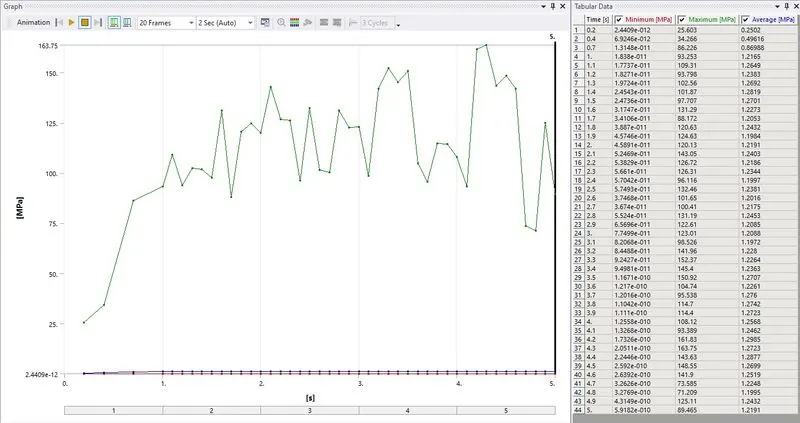
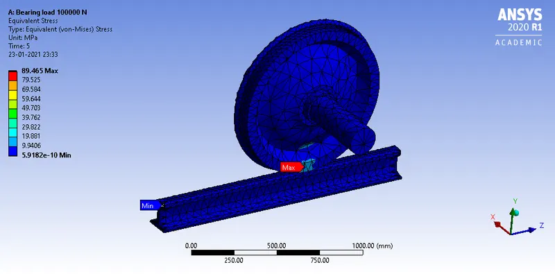
Equivalent Stress
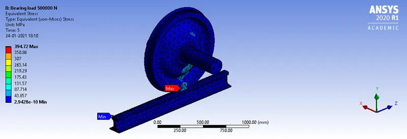
For 100000 N Bearing Load
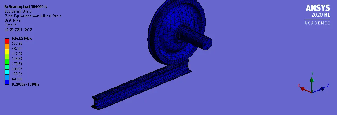
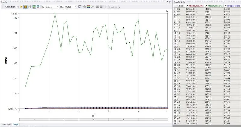
For 500000 N Bearing Load
| Bearing Load | Max. Total Deformation (mm) | Max. Equivalent Elastic Strain (mm/mm) | Max. Equivalent Stress (MPa) |
| 100000 N | 999.08 | 0.0013156 | 166.46 |
| 500000 N | 999.23 | 0.0035406 | 626.92 |
So it can be observed that for both the bearing load the total deformation is similar also there is not much difference in strain but in case of 100 KN bearing load the max. stress is 166.46 MPa which is below the tensile yield strength of the material structural steel which is 250 MPa while for the bearing load of 500 KN the max. stress is 626.92 MPa which is over the tensile ultimate strength of the material structural steel which is 460 MPa.
Case 2: Implement a User-defined result and calculate the Total Deformation from this result and check if it is the same as that obtained by the inbuilt result by ANSYS for a load of 100000 N.
PROCEDURE:-
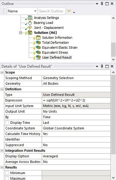
- To define a user-defined result in the model edit solution section right-click to insert User-defined result.
- For the required output result in the user-defined result respective expression is to be provided.
- So, lets first understand what Directional Deformation and Total Deformation is, when an analysis is performed, displacement occurs in 3 directions, viz., X, Y and Z and the user can check the deformation in the desired direction which is called directional deformation while total deformation is the overall deformation of the system and it is the square root of the summation of the square of x-direction, y-direction and z-direction. The expression for the Total deformation is
Total Deformation `= sqrt(UX^2 + UY^2 + UZ^2)`
RESULT:-
User-defined Total Deformation
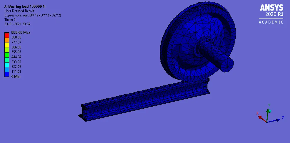
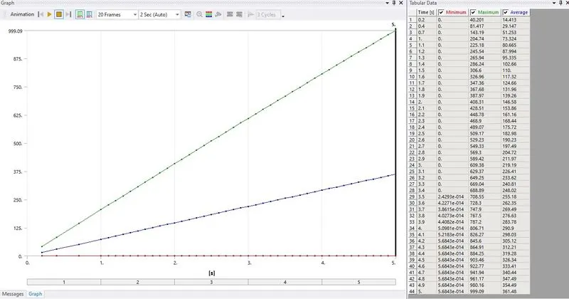
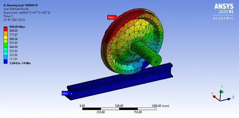
Total Deformation For 100000 N Bearing Load
- The result obtained by the user-defined expression for the total deformation is similar to the result obtained from the total deformation for the 100 KN bearing load.
CONCLUSION:-
So by completing the analysis it can be inferred that the stress experienced by the bearing load of 100 KN is under the limit of the tensile yield strength for the material structural steel while for the bearing load of 500 KN the stress experienced is above the tensile ultimate strength for the material structural steel.
Simulation File= https://drive.google.com/file/d/1mIMSIV6Txr5aMB68c1B2M0ocLY5nSj8u/view?usp=sharing